2009 GMC SAVANA PASSENGER wiring
[x] Cancel search: wiringPage 82 of 406

Adding Equipment to Your
Airbag-Equipped Vehicle
Q:Is there anything I might add to or change
about the vehicle that could keep the airbags
from working properly?
A:Yes. If you add things that change the vehicle’s
frame, bumper system, height, front end or side
sheet metal, they may keep the airbag system from
working properly. Changing or moving any parts
of the front seats, safety belts, the airbag sensing
and diagnostic module, steering wheel, instrument
panel, roof-rail airbag modules, ceiling headliner
or pillar garnish trim, front sensors, or airbag wiring
can affect the operation of the airbag system.
In addition, the vehicle may have a passenger
sensing system for the right front passenger
position, which includes sensors that are part of the
passenger seat. The passenger sensing system
may not operate properly if the original seat trim is
replaced with non-GM covers, upholstery or
trim, or with GM covers, upholstery or trim designed
for a different vehicle. Any object, such as an
aftermarket seat heater or a comfort enhancing pad
or device, installed under or on top of the seat
fabric, could also interfere with the operation of the
passenger sensing system. This could eitherprevent proper deployment of the passenger
airbag(s) or prevent the passenger sensing system
from properly turning off the passenger airbag(s).
SeePassenger Sensing System on page 1-71.
If you have any questions about this, you should
contact Customer Assistance before you modify the
vehicle. The phone numbers and addresses for
Customer Assistance are in Step Two of the
Customer Satisfaction Procedure in this manual.
SeeCustomer Satisfaction Procedure on page 7-2.
If the vehicle has rollover roof-rail airbags, see
Different Size Tires and Wheels on page 5-75for
additional important information.
Q:Because I have a disability, I have to get my
vehicle modi�ed. How can I �nd out whether
this will affect my airbag system?
A:If you have questions, call Customer Assistance.
The phone numbers and addresses for Customer
Assistance are in Step Two of the Customer
Satisfaction Procedure in this manual. See
Customer Satisfaction Procedure on page 7-2.
In addition, your dealer/retailer and the service manual
have information about the location of the airbag
sensors, sensing and diagnostic module and airbag
wiring.
1-78
Page 145 of 406

Airbag Readiness Light
The system checks the airbag’s electrical system for
possible malfunctions. If the light stays on it indicates
there is an electrical problem. The system check
includes the airbag sensor, the pretensioners, the airbag
modules, the wiring and the crash sensing and
diagnostic module. For more information on the airbag
system, seeAirbag System on page 1-58.
The airbag readiness light
flashes for a few seconds
when the engine is
started. If the light does
not come on then, have it
fixed immediately.{CAUTION:
If the airbag readiness light stays on after the
vehicle is started or comes on while driving, it
means the airbag system might not be working
properly. The airbags in the vehicle might not
inflate in a crash, or they could even inflate
without a crash. To help avoid injury, have the
vehicle serviced right away.
If there is a problem with the airbag system, an airbag
Driver Information Center (DIC) message can also come
on. SeeDIC Warnings and Messages on page 3-48
for more information.
3-27
Page 182 of 406
Audio System(s)
If the vehicle came without a radio, the wiring provisions
for a radio and an antenna were installed at the
assembly plant, so that if you want, a radio can be
installed at the dealer/retailer.
Determine which radio the vehicle has and read the
following pages to become familiar with its features.
{CAUTION:
Taking your eyes off the road for extended periods
could cause a crash resulting in injury or death to
you or others. Do not give extended attention to
entertainment tasks while driving.
This system provides access to many audio and non
audio listings.
To minimize taking your eyes off the road while driving,
do the following while the vehicle is parked:
•Become familiar with the operation and controls of
the audio system.
•Set up the tone, speaker adjustments, and preset
radio stations.For more information, seeDefensive Driving on
page 4-2.
Notice:Contact your dealer/retailer before adding
any equipment.
Adding audio or communication equipment could
interfere with the operation of the vehicle’s engine,
radio, or other systems, and could damage them.
Follow federal rules covering mobile radio and
telephone equipment.
Notice:The chime signals related to safety belts,
parking brake, and other functions of your vehicle
operate through the radio/entertainment system.
If that equipment is replaced or additional equipment
is added to your vehicle, the chimes may not
work. Make sure that replacement or additional
equipment is compatible with your vehicle before
installing it. SeeAccessories and Modifications
on page 5-3.
The vehicle has Retained Accessory Power (RAP). With
RAP, the audio system can be played even after the
ignition is turned off. SeeRetained Accessory Power
(RAP) on page 2-20for more information.
3-64
Page 237 of 406
If the loaded trailer being pulled will weigh more than
5,000 lbs (2 270 kg), be sure to use a properly mounted
weight-distributing hitch and sway control of the proper
size. This equipment is very important for proper vehicle
loading and good handling when driving. Always use a
sway control if the trailer will weigh more than these
limits. Ask a hitch dealer about sway controls.
Will any holes need to be made in the body of the
vehicle when a trailer hitch is installed?
If using the wiring provided with the factory-installed
trailering package, no holes need to be made in
the body of the vehicle. However, if an aftermarket hitch
is installed, holes may need to be made in the body.
If holes are made in the body, then be sure to seal the
holes later when the hitch is removed. If the holes
are not sealed, deadly carbon monoxide (CO) from the
engine’s exhaust can get into the vehicle as well as
dirt and water. See “Carbon Monoxide” underEngine
Exhaust on page 2-30.
Safety Chains
Always attach chains between the vehicle and the
trailer. Cross the safety chains under the tongue of the
trailer to help prevent the tongue from contacting
the road if it becomes separated from the hitch. Always
leave just enough slack so the rig can turn. Never
allow safety chains to drag on the ground.
Tow/Haul Mode
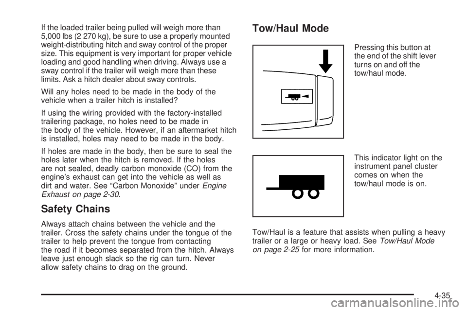
Pressing this button at
the end of the shift lever
turns on and off the
tow/haul mode.
This indicator light on the
instrument panel cluster
comes on when the
tow/haul mode is on.
Tow/Haul is a feature that assists when pulling a heavy
trailer or a large or heavy load. SeeTow/Haul Mode
on page 2-25for more information.
4-35
Page 242 of 406
Trailer Wiring Harness
The optional heavy-duty trailer wiring package includes
a wiring harness, with a seven-pin connector at the
rear of the vehicle and a four-wire harness assembly
under the driver side of the instrument panel. The
four-wire harness assembly comes without a connector.
If the vehicle does not have a trailer hitch, the
seven-wire harness assembly with connector is taped
together and located in a frame pocket at the driver side
rear left corner of the frame.
If the vehicle has a trailer hitch, the seven-wire harness
assembly with connector is attached to a bracket on
the hitch platform. In both cases, the seven-wire harness
has a connector and includes a 30-amp feed wire.
The seven-wire harness connector contains the following
trailer circuits:
•Light Green: Back-up Lamps (10A fuse)**
•White: Ground
•Dark Blue: Trailer Brake Signal
•Dark Green: Right Rear Stop and Turn Signal*
•Red/Black Stripe: Battery Feed (30A Fuse)
•Brown: Trailer Park Lamp Supply Voltage
(15A fuse)**
•Yellow: Left Rear Stop and Turn Signal *The four-wire harness (without connector) contains the
following circuits:
•Black: Ground
•Red/White: Battery Feed
•Dark Blue: Trailer Brake Signal
•Light Blue: CHMSL/Stoplamp Supply Voltage
* If the vehicle is a cutaway with trailer provisions, a
15 amp fuse will be shared for both left/stop trailer turn
and right/stop trailer turn signals. However, the
cutaway lighting connector will have a 10 amp fuse for
each signal.
** If the vehicle is a cutaway with trailer provisions, a
15 amp fuse will be shared for trailer park lamps
and cutaway rear lighting connector park lamps. Also, a
10 amp fuse will be shared for trailer back-up lamps
and cutaway rear lighting connector back-up lamps.
4-40
Page 244 of 406
Tires..............................................................5-55
Tire Sidewall Labeling...................................5-56
Tire Terminology and Definitions.....................5-60
Inflation - Tire Pressure.................................5-63
Dual Tire Operation.......................................5-64
Tire Pressure Monitor System.........................5-65
Tire Pressure Monitor Operation.....................5-66
Tire Inspection and Rotation...........................5-70
When It Is Time for New Tires.......................5-72
Buying New Tires.........................................5-73
Different Size Tires and Wheels......................5-75
Uniform Tire Quality Grading..........................5-75
Wheel Alignment and Tire Balance..................5-77
Wheel Replacement......................................5-77
Tire Chains..................................................5-78
If a Tire Goes Flat........................................5-79
Changing a Flat Tire.....................................5-80
Removing the Spare Tire and Tools................5-81
Removing the Flat Tire and Installing the
Spare Tire................................................5-84
Secondary Latch System...............................5-91
Storing a Flat or Spare Tire and Tools............5-94
Spare Tire...................................................5-95
Appearance Care............................................5-96
Interior Cleaning...........................................5-96
Fabric/Carpet...............................................5-97Instrument Panel, Vinyl, and Other Plastic
Surfaces..................................................5-98
Care of Safety Belts......................................5-98
Weatherstrips...............................................5-98
Washing Your Vehicle...................................5-99
Cleaning Exterior Lamps/Lenses.....................5-99
Finish Care................................................5-100
Windshield and Wiper Blades.......................5-100
Aluminum Wheels.......................................5-101
Tires.........................................................5-101
Sheet Metal Damage...................................5-101
Finish Damage...........................................5-102
Underbody Maintenance...............................5-102
Chemical Paint Spotting...............................5-102
Vehicle Identi�cation.....................................5-103
Vehicle Identification Number (VIN)................5-103
Service Parts Identification Label...................5-103
Electrical System..........................................5-103
Add-On Electrical Equipment.........................5-103
Headlamp Wiring........................................5-104
Windshield Wiper Fuses...............................5-104
Fuses and Circuit Breakers..........................5-104
Floor Console Fuse Block............................5-104
Engine Compartment Fuse Block...................5-106
Capacities and Speci�cations........................5-110
Section 5 Service and Appearance Care
5-2
Page 346 of 406
Headlamp Wiring
The headlamp wiring is protected by fuses in the engine
compartment fuse block. An electrical overload will
cause the lamps to flicker on and off, or in some cases
to remain off. If this happens, have your headlamp
wiring checked right away.
Windshield Wiper Fuses
The windshield wiper motor is protected by a circuit
breaker and a fuse. If the motor overheats due to heavy
snow, etc., the wiper will stop until the motor cools.
Although the circuit is protected from electrical overload,
overload due to heavy snow, etc., may cause wiper
linkage damage. Always clear ice and heavy snow from
the windshield before using the windshield wipers. If the
overload is caused by some electrical problem and not
snow, etc., be sure to get it fixed.
Fuses and Circuit Breakers
The wiring circuits in the vehicle are protected from
short circuits by a combination of fuses and circuit
breakers. This greatly reduces the chance of fires
caused by electrical problems.
Look at the silver-colored band inside the fuse. If the
band is broken or melted, replace the fuse. Be sure
you replace a bad fuse with a new one of the identical
size and rating.
Floor Console Fuse Block
The floor console fuse block is located under the
driver seat.
5-104
Page 350 of 406

Fuse Usage
9 Right Low-Beam Headlamp
10 Daytime Running Lamps 2 (DRL)
11Fuel System Control Module
Ignition (Gas)
12 Daytime Running Lamps 1 (DRL)
13 Auxiliary Stoplamp
14Fuel Operated Heater
Module (Diesel)
15Fuel System Control Module
Battery (Gas)
16 Left Stoplamp, Trailer Turn Signal
17 Canister Vent Solenoid (Gas)
18 Empty
19 Empty
20 Body Control Module 1
21 Special Equipment Option (SEO)
22 Body Control Module 4
23 Body Control Module 6
24 Empty
25 Body Control Module 7
26 Body Control Module 3
27 Body Control Module 5
28 Empty
29 EmptyFuse Usage
30 Instrument Panel Cluster
31 Empty
32 Brake Switch
33 Auxiliary Power Outlet
34 Airbag
35 Trailer Wiring
36 Steering Wheel Sensor (Gas)
37 Body Control Module 2
38Cigarette Lighter, Data Link
Controller
39 Windshield Wiper
40 Empty
41 Windshield Washer
42 Empty
43 Horn
44Transmission Control Module
Battery
45 Empty
46 Oxygen Sensor 1 (Gas)
47Transmission Control Module
Ignition
48 Engine Control Module Ignition
49 Mass Airflow Sensor, Canister Vent
50 Engine Control Module, Powertrain
5-108