2009 GMC SAVANA remote start
[x] Cancel search: remote startPage 4 of 404

Vehicle Symbols
The vehicle has components and labels that use
symbols instead of text. Symbols are shown along with
the text describing the operation or information
relating to a specific component, control, message,
gage, or indicator.
M:This symbol is shown when you need to see your
owner manual for additional instructions or information.
*:This symbol is shown when you need to see a
service manual for additional instructions or information.
Vehicle Symbol Chart
Here are some additional symbols that may be found on
the vehicle and what they mean. For more information
on the symbol, refer to the index.
9:Airbag Readiness Light
#:Air Conditioning
!:Antilock Brake System (ABS)
g:Audio Steering Wheel Controls or OnStar®
$:Brake System Warning Light
":Charging System
I:Cruise Control
B:Engine Coolant Temperature
O:Exterior Lamps
#:Fog Lamps
.:Fuel Gage
+:Fuses
i:Headlamp High/Low-Beam Changer
j:LATCH System Child Restraints
*:Malfunction Indicator Lamp
::Oil Pressure
}:Power
/:Remote Vehicle Start
>:Safety Belt Reminders
7:Tire Pressure Monitor
_:Tow/Haul Mode
F:Traction Control
M:Windshield Washer Fluid
iv
Page 85 of 404

Keys...............................................................2-2
Remote Keyless Entry (RKE) System................2-3
Remote Keyless Entry (RKE) System
Operation...................................................2-4
Doors and Locks.............................................2-6
Door Locks....................................................2-6
Power Door Locks..........................................2-6
Cargo Door Relocking.....................................2-7
Delayed Locking.............................................2-7
Programmable Automatic Door Locks................2-7
Automatic Door Lock.......................................2-8
Automatic Door Unlock....................................2-8
Rear Door Security Locks................................2-8
Lockout Protection..........................................2-9
Sliding Side Door...........................................2-9
60/40 Swing-Out Side Door............................2-10
Rear Doors..................................................2-12
Windows........................................................2-13
Manual Windows..........................................2-13
Power Windows............................................2-14
Swing-Out Windows......................................2-15
Enhanced Technology Glass..........................2-16
Sun Visors...................................................2-16Theft-Deterrent Systems..................................2-16
PASS-Key®III+ Electronic Immobilizer.............2-17
PASS-Key®III+ Electronic Immobilizer
Operation.................................................2-17
Starting and Operating Your Vehicle................2-19
New Vehicle Break-In....................................2-19
Ignition Positions..........................................2-19
Retained Accessory Power (RAP)...................2-20
Starting the Engine.......................................2-20
Engine Coolant Heater..................................2-22
Automatic Transmission Operation...................2-23
Tow/Haul Mode............................................2-25
Parking Brake..............................................2-26
Shifting Into Park..........................................2-27
Shifting Out of Park......................................2-29
Parking Over Things That Burn.......................2-29
Engine Exhaust............................................2-30
Running the Vehicle While Parked..................2-31
Mirrors...........................................................2-32
Manual Rearview Mirror.................................2-32
Outside Manual Mirrors..................................2-32
Outside Towing Mirrors..................................2-32
Outside Power Mirrors...................................2-33
Outside Convex Mirror...................................2-33
Outside Heated Mirrors..................................2-34
Storage Areas................................................2-34
Section 2 Features and Controls
2-1
Page 162 of 404
T(Vehicle Information):Press this button to display
the oil life, units, tire pressure readings for vehicles with
the Tire Pressure Monitor System (TPMS), engine hours,
Tire Pressure Monitor System (TPMS) programming for
vehicles with the TPMS and without a Remote Keyless
Entry (RKE) transmitter, compass zone and compass
calibration on vehicles with this feature, and RKE
transmitter programming.
U(Customization):Press this button to customize the
feature settings on your vehicle. SeeDIC Vehicle
Customization on page 3-59for more information.
V(Set/Reset):Press this button to set or reset certain
functions and to turn off or acknowledge messages
on the DIC.
Trip/Fuel Menu Items
3
(Trip/Fuel):Press this button to scroll through the
following menu items:
Odometer
Press the trip/fuel button until XX mi (Km) displays.
This display shows the distance the vehicle has been
driven in either miles (mi) or kilometers (km).
Trip Odometers
Press the trip/fuel button until A or B displays. This
display shows the current distance traveled in either
miles (mi) or kilometers (km) since the last reset for each
trip odometer. Both trip odometers can be used at the
same time.
Each trip odometer can be reset to zero separately by
pressing the set/reset button while the desired trip
odometer is displayed.
The trip odometer has a feature called the retro-active
reset. This can be used to set the trip odometer to the
number of miles (kilometers) driven since the ignition was
last turned on. This can be used if the trip odometer is not
reset at the beginning of the trip.
To use the retro-active reset feature, press and hold
the set/reset button for at least four seconds. The trip
odometer will display the number of miles (mi) or
kilometers (km) driven since the ignition was last turned
on and the vehicle was moving. Once the vehicle begins
moving, the trip odometer will accumulate mileage. For
example, if the vehicle was driven 5 miles (8 km) before it
is started again, and then the retro-active reset feature is
activated, the display will show 5 miles (8 km). As the
vehicle begins moving, the display will then increase to
5.1 miles (8.2 km), 5.2 miles (8.4 km), etc.
3-44
Page 283 of 404
Notice:If you leave the radio or other accessories
on during the jump starting procedure, they could
be damaged. The repairs would not be covered by
the warranty. Always turn off the radio and other
accessories when jump starting the vehicle.
3. Turn off the ignition on both vehicles. Unplug
unnecessary accessories plugged into the cigarette
lighter or the accessory power outlet. Turn off the
radio and all lamps that are not needed. This will
avoid sparks and help save both batteries. And it
could save the radio!
4. Open the hoods and locate the positive (+) and
negative (−) terminal locations of the other vehicle.
Your vehicle has a remote positive (+) jump
starting terminal and a remote negative (−) jump
starting terminal. You should always use these
remote terminals instead of the terminals on the
battery.The remote positive (+) terminal is located
behind a red plastic cover near the engine accessory
drive bracket on the driver’s side of the engine
compartment, below the alternator. To uncover the
remote positive (+) terminal, open the red plastic
cover.
The remote negative (−) terminal is located on the
engine drive bracket on all V8 engines and is
marked GND (Ground).
On V6 engines the remote negative (−) terminal is
located on a tab attached to the engine accessory
drive bracket and is marked GND (Ground).
5-41
Page 285 of 404
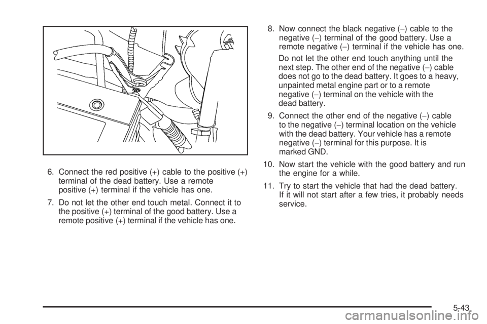
6. Connect the red positive (+) cable to the positive (+)
terminal of the dead battery. Use a remote
positive (+) terminal if the vehicle has one.
7. Do not let the other end touch metal. Connect it to
the positive (+) terminal of the good battery. Use a
remote positive (+) terminal if the vehicle has one.8. Now connect the black negative (−) cable to the
negative (−) terminal of the good battery. Use a
remote negative (−) terminal if the vehicle has one.
Do not let the other end touch anything until the
next step. The other end of the negative (−) cable
does not go to the dead battery. It goes to a heavy,
unpainted metal engine part or to a remote
negative (−) terminal on the vehicle with the
dead battery.
9. Connect the other end of the negative (−) cable
to the negative (−) terminal location on the vehicle
with the dead battery. Your vehicle has a remote
negative (−) terminal for this purpose. It is
marked GND.
10. Now start the vehicle with the good battery and run
the engine for a while.
11. Try to start the vehicle that had the dead battery.
If it will not start after a few tries, it probably needs
service.
5-43
Page 310 of 404

The TPMS sensor matching process is outlined below:
1. Set the parking brake.
2. Turn the ignition switch to ON/RUN with the
engine off.
3. Press the Remote Keyless Entry (RKE) transmitter’s
LOCK and UNLOCK buttons at the same time for
approximately five seconds. The horn sounds
twice to signal the receiver is in relearn mode
and TIRE LEARNING ACTIVE message displays
on the DIC screen.
If your vehicle does not have RKE, press the Driver
Information Center (DIC) vehicle information button
until the PRESS
VTO RELEARN TIRE POSITIONS
message displays. The horn sounds twice to signal
the receiver is in relearn mode and TIRE LEARNING
ACTIVE message displays on the DIC screen.
If your vehicle does not have RKE or DIC buttons,
press the trip odometer reset stem located on the
instrument panel cluster until the PRESS
VTO
RELEARN TIRE POSITIONS message displays.
The horn sounds twice to signal the receiver is in
relearn mode and TIRE LEARNING ACTIVE
message displays on the DIC screen.
4. Start with the driver side front tire.5. Remove the valve cap from the valve cap stem.
Activate the TPMS sensor by increasing or
decreasing the tire’s air pressure for five seconds,
or until a horn chirp sounds. The horn chirp,
which may take up to 30 seconds to sound,
confirms that the sensor identification code has
been matched to this tire and wheel position.
6. Proceed to the passenger side front tire, and repeat
the procedure in Step 5.
7. Proceed to the passenger side rear tire, and repeat
the procedure in Step 5.
8. Proceed to the driver side rear tire, and repeat the
procedure in Step 5. The horn sounds two times to
indicate the sensor identification code has been
matched to the driver side rear tire, and that
the TPMS sensor matching process is no longer
active. The TIRE LEARNING ACTIVE message
on the DIC display screen goes off.
9. Turn the ignition switch to LOCK/OFF.
10. Set all four tires to the recommended air pressure
level as indicated on the Tire and Loading
Information label.
11. Put the valve caps back on the valve stems.
5-68
Page 382 of 404
Calling for Assistance
When calling Roadside Assistance, have the following
information ready:
•Your name, home address, and home telephone
number
•Telephone number of your location
•Location of the vehicle
•Model, year, color, and license plate number of the
vehicle
•Odometer reading, Vehicle Identification
Number (VIN), and delivery date of the vehicle
•Description of the problem
Coverage
Services are provided up to 5 years/100,000 miles
(160 000 km), whichever comes first.
In the U.S., anyone driving the vehicle is covered.
In Canada, a person driving the vehicle without
permission from the owner is not covered.
Roadside Assistance is not a part of the New Vehicle
Limited Warranty. GMC and General Motors of Canada
Limited reserve the right to make any changes or
discontinue the Roadside Assistance program at any
time without notification.GMC and General Motors of Canada Limited reserve the
right to limit services or payment to an owner or driver if
they decide the claims are made too often, or the same
type of claim is made many times.
Services Provided
•Emergency Fuel Delivery:Delivery of enough fuel
for the vehicle to get to the nearest service station.
•Lock-Out Service:Service is provided to unlock the
vehicle if you are locked out. A remote unlock may be
available if you have OnStar
®. For security reasons,
the driver must present identification before this
service is given.
•Emergency Tow From a Public Road or Highway:
Tow to the nearest GMC dealer for warranty service,
or if the vehicle was in a crash and cannot be driven.
Assistance is also given when the vehicle is stuck in
the sand, mud, or snow.
•Flat Tire Change:Service is provided to change a
flat tire with the spare tire. The spare tire, if equipped,
must be in good condition and properly inflated.
It is the owner’s responsibility for the repair or
replacement of the tire if it is not covered by the
warranty.
•Battery Jump Start:Service is provided to jump
start a dead battery.
7-8
Page 392 of 404
OnStar®
If your vehicle has OnStar and you subscribe to the
OnStar services, please refer to the OnStar Terms
and Conditions for information on data collection
and use.
Navigation System
If your vehicle has a navigation system, use of the
system may result in the storage of destinations,
addresses, telephone numbers, and other trip
information. Refer to the navigation system operating
manual for information on stored data and for deletion
instructions.
Radio Frequency
Identi�cation (RFID)
RFID technology is used in some vehicles for functions
such as tire pressure monitoring and ignition system
security, as well as in connection with conveniences
such as key fobs for remote door locking/unlocking and
starting, and in-vehicle transmitters for garage door
openers. RFID technology in GM vehicles does not use
or record personal information or link with any other
GM system containing personal information.
7-18