2009 GMC SAVANA maintenance
[x] Cancel search: maintenancePage 286 of 404
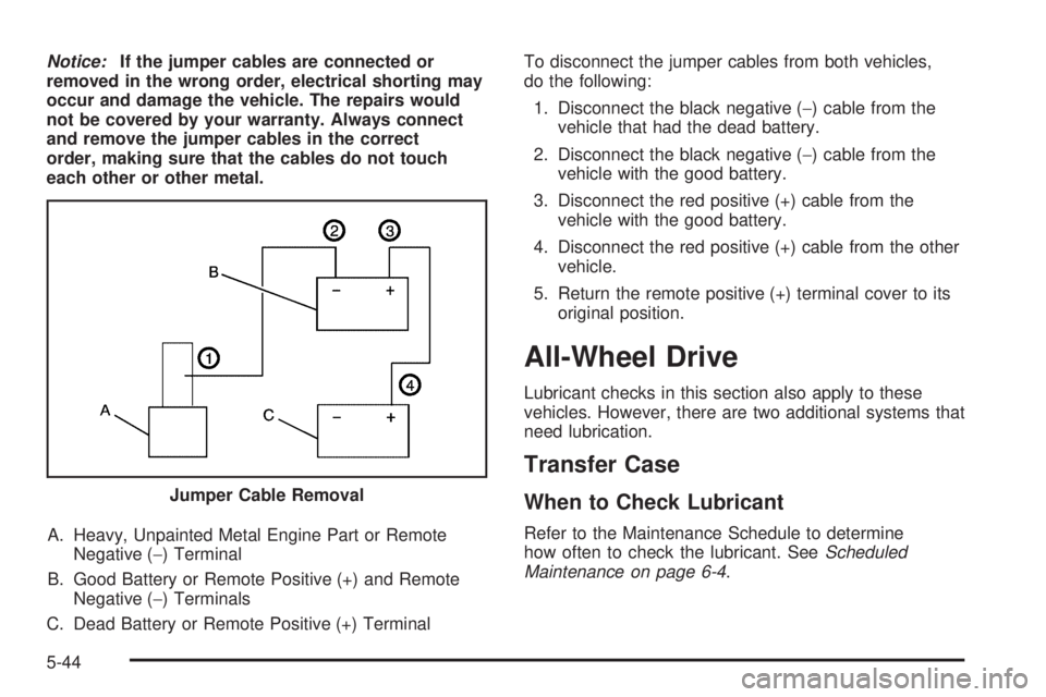
Notice:If the jumper cables are connected or
removed in the wrong order, electrical shorting may
occur and damage the vehicle. The repairs would
not be covered by your warranty. Always connect
and remove the jumper cables in the correct
order, making sure that the cables do not touch
each other or other metal.
A. Heavy, Unpainted Metal Engine Part or Remote
Negative (−) Terminal
B. Good Battery or Remote Positive (+) and Remote
Negative (−) Terminals
C. Dead Battery or Remote Positive (+) TerminalTo disconnect the jumper cables from both vehicles,
do the following:
1. Disconnect the black negative (−) cable from the
vehicle that had the dead battery.
2. Disconnect the black negative (−) cable from the
vehicle with the good battery.
3. Disconnect the red positive (+) cable from the
vehicle with the good battery.
4. Disconnect the red positive (+) cable from the other
vehicle.
5. Return the remote positive (+) terminal cover to its
original position.
All-Wheel Drive
Lubricant checks in this section also apply to these
vehicles. However, there are two additional systems that
need lubrication.
Transfer Case
When to Check Lubricant
Refer to the Maintenance Schedule to determine
how often to check the lubricant. SeeScheduled
Maintenance on page 6-4. Jumper Cable Removal
5-44
Page 287 of 404
What to Use
Refer to the Maintenance Schedule to determine what
kind of lubricant to use. SeeRecommended Fluids
and Lubricants on page 6-13.
How to Check Lubricant
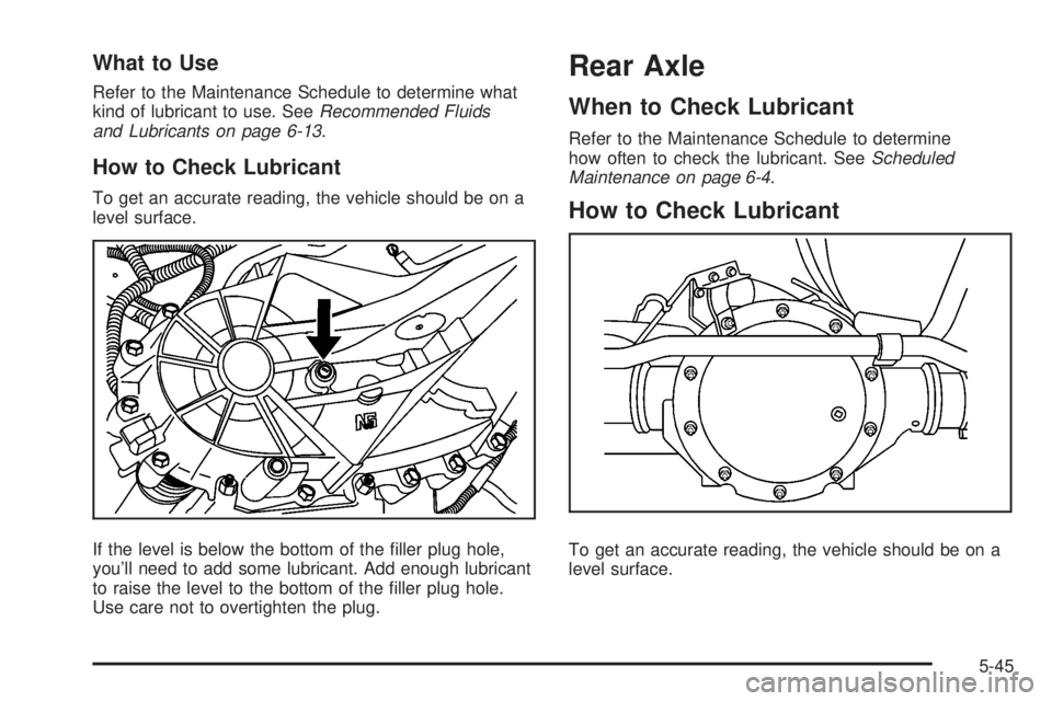
To get an accurate reading, the vehicle should be on a
level surface.
If the level is below the bottom of the filler plug hole,
you’ll need to add some lubricant. Add enough lubricant
to raise the level to the bottom of the filler plug hole.
Use care not to overtighten the plug.
Rear Axle
When to Check Lubricant
Refer to the Maintenance Schedule to determine
how often to check the lubricant. SeeScheduled
Maintenance on page 6-4.
How to Check Lubricant
To get an accurate reading, the vehicle should be on a
level surface.
5-45
Page 288 of 404
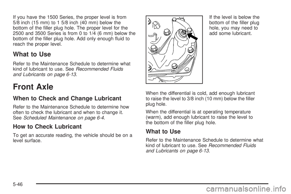
If you have the 1500 Series, the proper level is from
5/8 inch (15 mm) to 1 5/8 inch (40 mm) below the
bottom of the filler plug hole. The proper level for the
2500 and 3500 Series is from 0 to 1/4 (6 mm) below the
bottom of the filler plug hole. Add only enough fluid to
reach the proper level.
What to Use
Refer to the Maintenance Schedule to determine what
kind of lubricant to use. SeeRecommended Fluids
and Lubricants on page 6-13.
Front Axle
When to Check and Change Lubricant
Refer to the Maintenance Schedule to determine how
often to check the lubricant and when to change it.
SeeScheduled Maintenance on page 6-4.
How to Check Lubricant
To get an accurate reading, the vehicle should be on a
level surface.If the level is below the
bottom of the filler plug
hole, you may need to
add some lubricant.
When the differential is cold, add enough lubricant
to raise the level to 3/8 inch (10 mm) below the filler
plug hole.
When the differential is at operating temperature
(warm), add enough lubricant to raise the level to
the bottom of the filler plug hole.What to Use
Refer to the Maintenance Schedule to determine what
kind of lubricant to use. SeeRecommended Fluids
and Lubricants on page 6-13.
5-46
Page 289 of 404
Noise Control System
Tampering with Noise Control
System Prohibited
The following information relates to compliance with
federal noise emission standards for vehicles with
a Gross Vehicle Weight Rating (GVWR) of more than
10,000 lbs (4 536 kg). The Maintenance Schedule
provides information on maintaining the noise
control system to minimize degradation of the noise
emission control system during the life of your vehicle.
The noise control system warranty is given in your
warranty booklet.
These standards apply only to vehicles sold in the
United States.
Federal law prohibits the following acts or the causing
thereof:
1. The removal or rendering inoperative by any
person, other than for purposes of maintenance,
repair or replacement, of any device or element
of design incorporated into any new vehicle for
the purpose of noise control, prior to its sale
or delivery to the ultimate purchaser or while
it is in use; or
2. The use of the vehicle after such device or element
of design has been removed or rendered inoperative
by any person.Among those acts presumed to constitute tampering are
the acts listed below.
Insulation:
•
Removal of the noise shields or any underhood
insulation.
Engine:
•
Removal or rendering engine speed governor, if the
vehicle has one, inoperative so as to allow engine
speed to exceed manufacturer specifications.
Fan and Drive:
•
Removal of fan clutch, if the vehicle has one, or
rendering clutch inoperative.
•Removal of the fan shroud, if the vehicle has one.
Air Intake:
•
Removal of the air cleaner silencer.
•Modification of the air cleaner.
Exhaust:
•
Removal of the muffler and/or resonator.
•Removal of the exhaust pipes and exhaust pipe
clamps.
Fuel Operated Heater (FOH) — Diesel
Engine:
•
Removal of the muffler.
5-47
Page 295 of 404
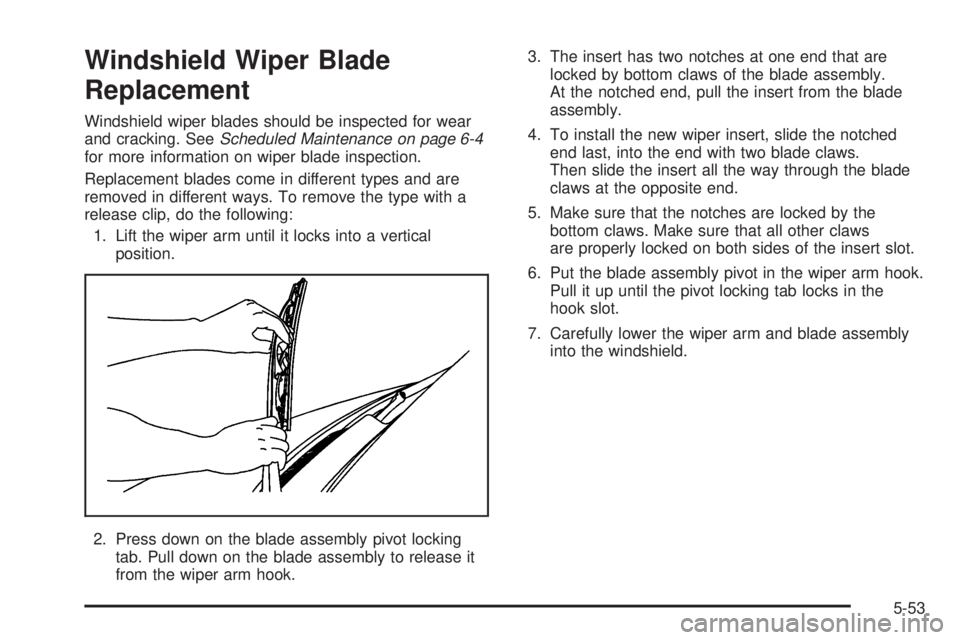
Windshield Wiper Blade
Replacement
Windshield wiper blades should be inspected for wear
and cracking. SeeScheduled Maintenance on page 6-4
for more information on wiper blade inspection.
Replacement blades come in different types and are
removed in different ways. To remove the type with a
release clip, do the following:
1. Lift the wiper arm until it locks into a vertical
position.
2. Press down on the blade assembly pivot locking
tab. Pull down on the blade assembly to release it
from the wiper arm hook.3. The insert has two notches at one end that are
locked by bottom claws of the blade assembly.
At the notched end, pull the insert from the blade
assembly.
4. To install the new wiper insert, slide the notched
end last, into the end with two blade claws.
Then slide the insert all the way through the blade
claws at the opposite end.
5. Make sure that the notches are locked by the
bottom claws. Make sure that all other claws
are properly locked on both sides of the insert slot.
6. Put the blade assembly pivot in the wiper arm hook.
Pull it up until the pivot locking tab locks in the
hook slot.
7. Carefully lower the wiper arm and blade assembly
into the windshield.
5-53
Page 305 of 404
How to Check
Use a good quality pocket-type gage to check
tire pressure. You cannot tell if your tires are
properly inflated simply by looking at them. Radial
tires may look properly inflated even when they are
underinflated. Check the tire’s inflation pressure
when the tires are cold. Cold means your vehicle
has been sitting for at least three hours or driven
no more than 1 mile (1.6 km).
Remove the valve cap from the tire valve stem.
Press the tire gage firmly onto the valve to get a
pressure measurement. If the cold tire inflation
pressure matches the recommended pressure on
the Tire and Loading Information label, no further
adjustment is necessary. If the pressure is low, add
air until you reach the recommended amount.
If you overfill the tire, release air by pushing on
the metal stem in the center of the tire valve.
Recheck the tire pressure with the tire gage.
Be sure to put the valve caps back on the valve
stems. They help prevent leaks by keeping out dirt
and moisture.
Dual Tire Operation
When the vehicle is new, or whenever a wheel, wheel
bolt or wheel nut is replaced, check the wheel nut torque
after 100, 1,000 and 6,000 miles (160, 1 600 and
10 000 km) of driving. For proper wheel nut tightening
information, see “Removing the Flat Tire and Installing
the Spare Tire” later in this section, underChanging a
Flat Tire on page 5-80. Also see “Wheel Nut Torque”
underCapacities and Specifications on page 5-110.
The outer tire on a dual wheel setup generally wears
faster than the inner tire. Your tires will wear more
evenly and last longer if you rotate the tires periodically.
SeeTire Inspection and Rotation on page 5-69.
Also seeScheduled Maintenance on page 6-4.
{CAUTION:
If you operate your vehicle with a tire that is badly
underinflated, the tire can overheat. An overheated
tire can lose air suddenly or catch fire. You or
others could be injured. Be sure all tires (including
the spare) are properly inflated.
SeeTires on page 5-54andInflation - Tire Pressure on
page 5-62for more information on proper tire inflation.
5-63
Page 306 of 404

Tire Pressure Monitor System
The Tire Pressure Monitor System (TPMS) uses radio
and sensor technology to check tire pressure levels.
The TPMS sensors monitor the air pressure in
your vehicle’s tires and transmit tire pressure
readings to a receiver located in the vehicle.
Each tire, including the spare (if provided), should be
checked monthly when cold and inflated to the inflation
pressure recommended by the vehicle manufacturer
on the vehicle placard or tire inflation pressure label.
(If your vehicle has tires of a different size than the
size indicated on the vehicle placard or tire inflation
pressure label, you should determine the proper
tire inflation pressure for those tires.)
As an added safety feature, your vehicle has been
equipped with a tire pressure monitoring system (TPMS)
that illuminates a low tire pressure telltale when one
or more of your tires is significantly under-inflated.
Accordingly, when the low tire pressure telltale
illuminates, you should stop and check your tires
as soon as possible, and inflate them to the proper
pressure. Driving on a significantly under-inflated
tire causes the tire to overheat and can lead to tire
failure. Under-inflation also reduces fuel efficiency
and tire tread life, and may affect the vehicle’s handling
and stopping ability.Please note that the TPMS is not a substitute for proper
tire maintenance, and it is the driver’s responsibility to
maintain correct tire pressure, even if under-inflation
has not reached the level to trigger illumination of
the TPMS low tire pressure telltale.
Your vehicle has also been equipped with a TPMS
malfunction indicator to indicate when the system is not
operating properly. The TPMS malfunction indicator is
combined with the low tire pressure telltale. When the
system detects a malfunction, the telltale will flash for
approximately one minute and then remain continuously
illuminated. This sequence will continue upon
subsequent vehicle start-ups as long as the malfunction
exists.
When the malfunction indicator is illuminated, the
system may not be able to detect or signal low tire
pressure as intended. TPMS malfunctions may occur
for a variety of reasons, including the installation of
replacement or alternate tires or wheels on the vehicle
that prevent the TPMS from functioning properly. Always
check the TPMS malfunction telltale after replacing one
or more tires or wheels on your vehicle to ensure that
the replacement or alternate tires and wheels allow the
TPMS to continue to function properly.
SeeTire Pressure Monitor Operation on page 5-65for
additional information.
5-64
Page 308 of 404

The low tire pressure warning light may come on in
cool weather when the vehicle is first started, and then
turn off as you start to drive. This could be an early
indicator that the air pressure in the tire(s) are getting
low and need to be inflated to the proper pressure.
A Tire and Loading Information label, attached to
your vehicle, shows the size of your vehicle’s original
equipment tires and the correct inflation pressure for
your vehicle’s tires when they are cold. SeeLoading the
Vehicle on page 4-18, for an example of the Tire and
Loading Information label and its location on your vehicle.
Also seeInflation - Tire Pressure on page 5-62.
Your vehicle’s TPMS can warn you about a low tire
pressure condition but it does not replace normal
tire maintenance. SeeTire Inspection and Rotation
on page 5-69andTires on page 5-54.
Notice:Liquid tire sealants could damage the Tire
Pressure Monitor System (TPMS) sensors. Sensor
damage caused by using a tire sealant is not
covered by your warranty. Do not use liquid tire
sealants.TPMS Malfunction Light and Message
The TPMS will not function properly if one or more of
the TPMS sensors are missing or inoperable. When the
system detects a malfunction, the low tire warning light
flashes for about one minute and then stays on for the
remainder of the ignition cycle. A DIC warning message
is also displayed. The low tire warning light and DIC
warning message come on at each ignition cycle until
the problem is corrected. Some of the conditions that
can cause the malfunction light and DIC message to
come on are:
•One of the road tires has been replaced with the
spare tire. The spare tire does not have a TPMS
sensor. The TPMS malfunction light and DIC
message should go off once you re-install the
road tire containing the TPMS sensor.
•The TPMS sensor matching process was started but
not completed or not completed successfully after
rotating the vehicle’s tires. The DIC message and
TPMS malfunction light should go off once the TPMS
sensor matching process is performed successfully.
See “TPMS Sensor Matching Process” later in this
section.
5-66