Page 323 of 418
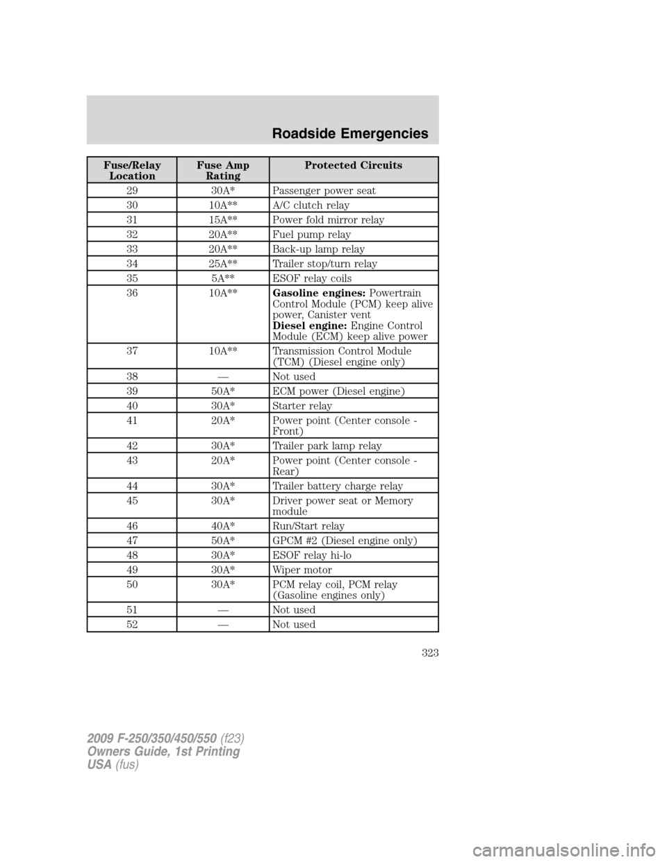
Fuse/Relay
LocationFuse Amp
RatingProtected Circuits
29 30A* Passenger power seat
30 10A** A/C clutch relay
31 15A** Power fold mirror relay
32 20A** Fuel pump relay
33 20A** Back-up lamp relay
34 25A** Trailer stop/turn relay
35 5A** ESOF relay coils
36 10A**Gasoline engines:Powertrain
Control Module (PCM) keep alive
power, Canister vent
Diesel engine:Engine Control
Module (ECM) keep alive power
37 10A** Transmission Control Module
(TCM) (Diesel engine only)
38 — Not used
39 50A* ECM power (Diesel engine)
40 30A* Starter relay
41 20A* Power point (Center console -
Front)
42 30A* Trailer park lamp relay
43 20A* Power point (Center console -
Rear)
44 30A* Trailer battery charge relay
45 30A* Driver power seat or Memory
module
46 40A* Run/Start relay
47 50A* GPCM #2 (Diesel engine only)
48 30A* ESOF relay hi-lo
49 30A* Wiper motor
50 30A* PCM relay coil, PCM relay
(Gasoline engines only)
51 — Not used
52 — Not used
2009 F-250/350/450/550(f23)
Owners Guide, 1st Printing
USA(fus)
Roadside Emergencies
323
Page 324 of 418
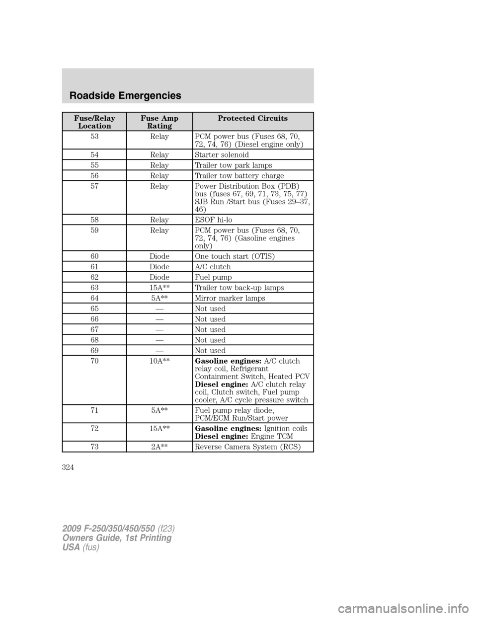
Fuse/Relay
LocationFuse Amp
RatingProtected Circuits
53 Relay PCM power bus (Fuses 68, 70,
72, 74, 76) (Diesel engine only)
54 Relay Starter solenoid
55 Relay Trailer tow park lamps
56 Relay Trailer tow battery charge
57 Relay Power Distribution Box (PDB)
bus (fuses 67, 69, 71, 73, 75, 77)
SJB Run /Start bus (Fuses 29–37,
46)
58 Relay ESOF hi-lo
59 Relay PCM power bus (Fuses 68, 70,
72, 74, 76) (Gasoline engines
only)
60 Diode One touch start (OTIS)
61 Diode A/C clutch
62 Diode Fuel pump
63 15A** Trailer tow back-up lamps
64 5A** Mirror marker lamps
65 — Not used
66 — Not used
67 — Not used
68 — Not used
69 — Not used
70 10A**Gasoline engines:A/C clutch
relay coil, Refrigerant
Containment Switch, Heated PCV
Diesel engine:A/C clutch relay
coil, Clutch switch, Fuel pump
cooler, A/C cycle pressure switch
71 5A** Fuel pump relay diode,
PCM/ECM Run/Start power
72 15A**Gasoline engines:Ignition coils
Diesel engine:Engine TCM
73 2A** Reverse Camera System (RCS)
2009 F-250/350/450/550(f23)
Owners Guide, 1st Printing
USA(fus)
Roadside Emergencies
324
Page 325 of 418

Fuse/Relay
LocationFuse Amp
RatingProtected Circuits
74 20A**Gasoline engines:VPWR:
HEGO, CMS, MAFS, EVMV,
CMCV, VCT, IMTV
Diesel engine:VPWR: Engine
loads
75 5A** Back-up relay coil power
76 20A**Gasoline engines:VPWR: PCM
Diesel engine:VPWR: ECM
77 10A** ABS module logic
* Cartridge fuses ** Mini fuses
CHANGING A FLAT TIRE
If you get a flat tire while driving:
•do not brake heavily.
•gradually decrease the vehicle’s speed.
•hold the steering wheel firmly.
•slowly move to a safe place on the side of the road.
Your vehicle may be equipped with a conventional spare tire that is
different in one or more of the following: type, brand, size, speed rating
and tread design. If this is the case, this dissimilar spare tire is still rated
for your vehicle loads (GAWR and GVWR).Temporary spare tires are not
equipped with Tire Pressure Monitor System (TPMS) sensors if the
system is present.
WARNING:The use of tire sealant may damage your Tire
Pressure Monitoring System (if equipped) and should not be
used.
WARNING:If your vehicle is equipped with a Tire Pressure
Monitoring System, refer toTire Pressure Monitoring System
in theTires, Wheels and Loadingchapter for more information. If the
tire pressure monitor sensor becomes damaged, it will no longer
function.
2009 F-250/350/450/550(f23)
Owners Guide, 1st Printing
USA(fus)
Roadside Emergencies
325
Page 329 of 418
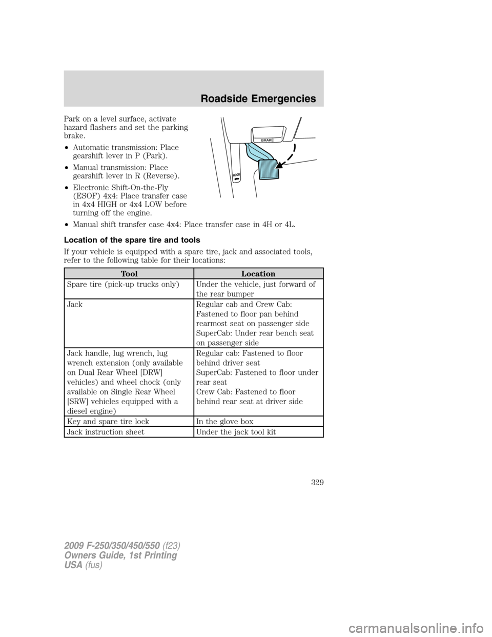
Park on a level surface, activate
hazard flashers and set the parking
brake.
•Automatic transmission: Place
gearshift lever in P (Park).
•Manual transmission: Place
gearshift lever in R (Reverse).
•Electronic Shift-On-the-Fly
(ESOF) 4x4: Place transfer case
in 4x4 HIGH or 4x4 LOW before
turning off the engine.
•Manual shift transfer case 4x4: Place transfer case in 4H or 4L.
Location of the spare tire and tools
If your vehicle is equipped with a spare tire, jack and associated tools,
refer to the following table for their locations:
Tool Location
Spare tire (pick-up trucks only) Under the vehicle, just forward of
the rear bumper
Jack Regular cab and Crew Cab:
Fastened to floor pan behind
rearmost seat on passenger side
SuperCab: Under rear bench seat
on passenger side
Jack handle, lug wrench, lug
wrench extension (only available
on Dual Rear Wheel [DRW]
vehicles) and wheel chock (only
available on Single Rear Wheel
[SRW] vehicles equipped with a
diesel engine)Regular cab: Fastened to floor
behind driver seat
SuperCab: Fastened to floor under
rear seat
Crew Cab: Fastened to floor
behind rear seat at driver side
Key and spare tire lock In the glove box
Jack instruction sheet Under the jack tool kit
2009 F-250/350/450/550(f23)
Owners Guide, 1st Printing
USA(fus)
Roadside Emergencies
329
Page 332 of 418
1. Turn engine off and block the
wheel that is diagonally opposite of
the flat tire using the wheel chock,
if equipped.If the vehicle is a
4x4,lock the manual hub on the
wheel.
2. Remove the jack, jack handle, lug wrench and spare tire from the
stowage locations.
3. Use the tip of the lug wrench to remove any wheel trim.
4. Loosen each wheel lug nut one-half turn counterclockwise but do not
remove them until the wheel is raised off the ground.
The following steps apply to F–250/F–350 Single Rear Wheel
(SRW) vehicles only:
5. Insert the hooked end of the jack
handle into the jack and use the
handle to slide the jack under the
vehicle.
6. Position the jack according to the
following guides:
•Front (4x2)
2009 F-250/350/450/550(f23)
Owners Guide, 1st Printing
USA(fus)
Roadside Emergencies
332
Page 334 of 418
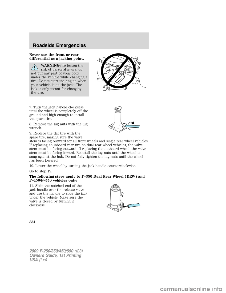
Never use the front or rear
differential as a jacking point.
WARNING:To lessen the
risk of personal injury, do
not put any part of your body
under the vehicle while changing a
tire. Do not start the engine when
your vehicle is on the jack. The
jack is only meant for changing
the tire.
7. Turn the jack handle clockwise
until the wheel is completely off the
ground and high enough to install
the spare tire.
8. Remove the lug nuts with the lug
wrench.
9. Replace the flat tire with the
spare tire, making sure the valve
stem is facing outward for all front wheels and single rear wheel vehicles.
If replacing an inboard rear tire on dual rear wheel vehicles, the valve
stem must be facing outward. If replacing the outboard wheel, the valve
stem must be facing inward. Reinstall the lug nuts until the wheel is
snug against the hub. Do not fully tighten the lug nuts until the wheel
has been lowered.
10. Lower the wheel by turning the jack handle counterclockwise.
Go to step 19.
The following steps apply to F–350 Dual Rear Wheel (DRW) and
F–450/F–550 vehicles only:
11. Slide the notched end of the
jack handle over the release valve
and use the handle to slide the jack
under the vehicle. Make sure the
valve is closed by turning it
clockwise.
2009 F-250/350/450/550(f23)
Owners Guide, 1st Printing
USA(fus)
Roadside Emergencies
334
Page 342 of 418
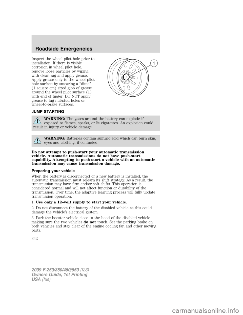
Inspect the wheel pilot hole prior to
installation. If there is visible
corrosion in wheel pilot hole,
remove loose particles by wiping
with clean rag and apply grease.
Apply grease only to the wheel pilot
hole surface by smearing a “dime”
(1 square cm) sized glob of grease
around the wheel pilot surface (1)
with end of finger. DO NOT apply
grease to lug nut/stud holes or
wheel-to-brake surfaces.
JUMP STARTING
WARNING:The gases around the battery can explode if
exposed to flames, sparks, or lit cigarettes. An explosion could
result in injury or vehicle damage.
WARNING:Batteries contain sulfuric acid which can burn skin,
eyes and clothing, if contacted.
Do not attempt to push-start your automatic transmission
vehicle. Automatic transmissions do not have push-start
capability. Attempting to push-start a vehicle with an automatic
transmission may cause transmission damage.
Preparing your vehicle
When the battery is disconnected or a new battery is installed, the
automatic transmission must relearn its shift strategy. As a result, the
transmission may have firm and/or soft shifts. This operation is
considered normal and will not affect function or durability of the
transmission. Over time, the adaptive learning process will fully update
transmission operation.
1.Use only a 12–volt supply to start your vehicle.
2. Do not disconnect the battery of the disabled vehicle as this could
damage the vehicle’s electrical system.
3. Park the booster vehicle close to the hood of the disabled vehicle
making sure the two vehiclesdo nottouch. Set the parking brake on
both vehicles and stay clear of the engine cooling fan and other moving
parts.
2009 F-250/350/450/550(f23)
Owners Guide, 1st Printing
USA(fus)
Roadside Emergencies
342
Page 344 of 418
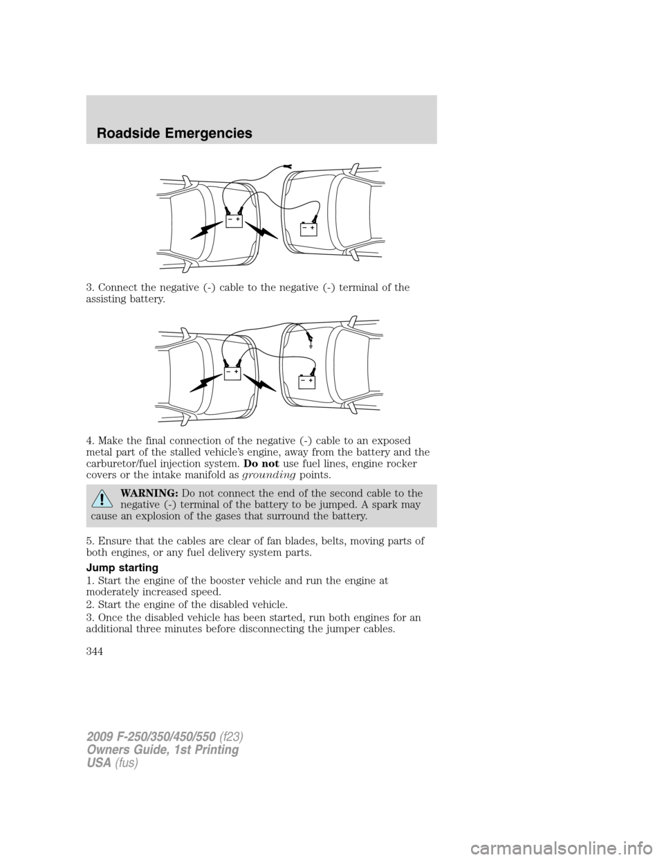
3. Connect the negative (-) cable to the negative (-) terminal of the
assisting battery.
4. Make the final connection of the negative (-) cable to an exposed
metal part of the stalled vehicle’s engine, away from the battery and the
carburetor/fuel injection system.Do notuse fuel lines, engine rocker
covers or the intake manifold asgroundingpoints.
WARNING:Do not connect the end of the second cable to the
negative (-) terminal of the battery to be jumped. A spark may
cause an explosion of the gases that surround the battery.
5. Ensure that the cables are clear of fan blades, belts, moving parts of
both engines, or any fuel delivery system parts.
Jump starting
1. Start the engine of the booster vehicle and run the engine at
moderately increased speed.
2. Start the engine of the disabled vehicle.
3. Once the disabled vehicle has been started, run both engines for an
additional three minutes before disconnecting the jumper cables.
+–+–
+–+–
2009 F-250/350/450/550(f23)
Owners Guide, 1st Printing
USA(fus)
Roadside Emergencies
344