Page 2 of 312
Locks and Security 91
Keys 91
Locks 93
Anti-theft system 106
Seating and Safety Restraints 112
Seating 112
Safety restraints 121
Airbags 135
Child restraints 150
Tires, Wheels and Loading 166
Tire information 166
Tire inflation 168
Tire Pressure Monitoring System (TPMS) 181
Vehicle loading 187
Trailer towing 191
Recreational towing 191
Driving 193
Starting 193
Brakes 198
AdvanceTrac�200
Traction Control™ 204
Transmission operation 206
Reverse sensing system 213
Roadside Emergencies 221
Getting roadside assistance 221
Hazard flasher switch 222
Fuel pump shut-off switch 223
Fuses and relays 223
Changing tires 230
Wheel lug nut torque 235
Jump starting 236
Wrecker towing 242
Table of Contents
2
2009 Fusion(fsn)
Owners Guide
USA(fus)
Page 8 of 312
These are some of the symbols you may see on your vehicle.
Vehicle Symbol Glossary
Safety Alert
See Owner’s Guide
Fasten Safety BeltAirbag - Front
Airbag - SideChild Seat Lower
Anchor
Child Seat Tether
AnchorBrake System
Anti-Lock Brake SystemParking Brake System
Brake Fluid -
Non-Petroleum BasedParking Aid System
Stability Control SystemSpeed Control
Master Lighting SwitchHazard Warning Flasher
Fog Lamps-FrontFuse Compartment
Fuel Pump ResetWindshield Wash/Wipe
Windshield
Defrost/DemistRear Window
Defrost/Demist
2009 Fusion(fsn)
Owners Guide
USA(fus)
Introduction
8
Page 9 of 312
Vehicle Symbol Glossary
Power Windows
Front/Rear
Power Window Lockout
Child Safety Door
Lock/UnlockInterior Luggage
Compartment Release
Panic AlarmEngine Oil
Engine CoolantEngine Coolant
Temperature
Do Not Open When HotBattery
Avoid Smoking, Flames,
or SparksBattery Acid
Explosive GasFan Warning
Power Steering FluidMaintain Correct Fluid
LevelMAX
MIN
Service Engine SoonEngine Air Filter
Passenger Compartment
Air FilterJack
Check Fuel CapLow Tire Pressure
Warning
2009 Fusion(fsn)
Owners Guide
USA(fus)
Introduction
9
Page 61 of 312
WARNING:Handle a halogen headlamp bulb carefully and keep
out of children’s reach. Grasp the bulb only by its plastic base
and do not touch the glass. The oil from your hand could cause the
bulb to break the next time the headlamps are operated.
7. For ease of bulb socket installation into the lamp assembly, hold the
bulb socket at 15 degrees clockwise from a vertical position. Use the two
lead wires oriented up to represent the vertical reference position.
8. From the 15 degree position, rotate the bulb socket clockwise to a
locked position.
9. Tuck the two lead wires into the lamp housing to assure that they are
not pinched when installing the protective rubber cap.
10. Install the protective cap/grill to the housing circular ring by pushing
and pressing it forward.
11. Re-apply pressure around the complete circular ring on the housing
to make sure the protective cap is completely seated.
12. Reconnect the washer bottle neck by reversing Step 3 (Passenger
side only).
13. Turn the headlamps on and make sure they work properly. If the
headlamp was correctly aligned before you changed the bulb, you should
not need to align it again.
Lowbeam bulb (upper) replacement
1. Make sure headlamp switch is in the off position, then open the hood.
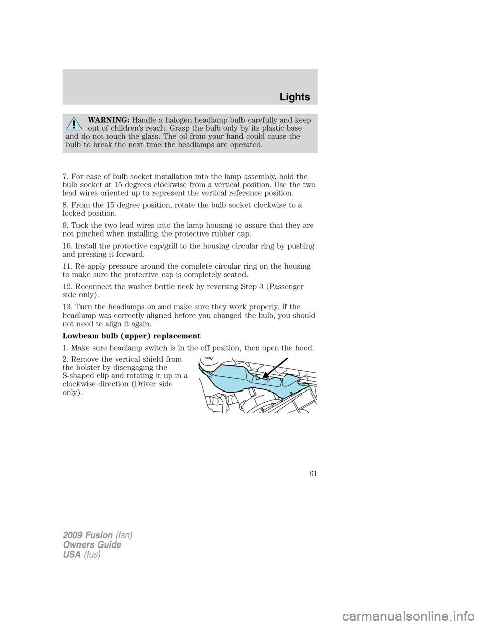
2. Remove the vertical shield from
the bolster by disengaging the
S-shaped clip and rotating it up in a
clockwise direction (Driver side
only).
2009 Fusion(fsn)
Owners Guide
USA(fus)
Lights
61
Page 63 of 312
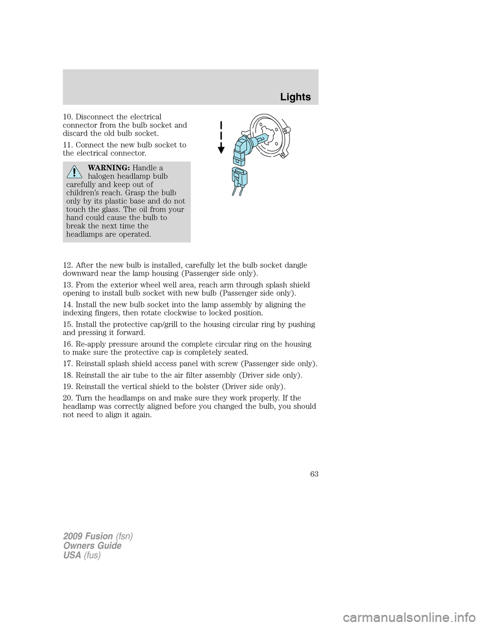
10. Disconnect the electrical
connector from the bulb socket and
discard the old bulb socket.
11. Connect the new bulb socket to
the electrical connector.
WARNING:Handle a
halogen headlamp bulb
carefully and keep out of
children’s reach. Grasp the bulb
only by its plastic base and do not
touch the glass. The oil from your
hand could cause the bulb to
break the next time the
headlamps are operated.
12. After the new bulb is installed, carefully let the bulb socket dangle
downward near the lamp housing (Passenger side only).
13. From the exterior wheel well area, reach arm through splash shield
opening to install bulb socket with new bulb (Passenger side only).
14. Install the new bulb socket into the lamp assembly by aligning the
indexing fingers, then rotate clockwise to locked position.
15. Install the protective cap/grill to the housing circular ring by pushing
and pressing it forward.
16. Re-apply pressure around the complete circular ring on the housing
to make sure the protective cap is completely seated.
17. Reinstall splash shield access panel with screw (Passenger side only).
18. Reinstall the air tube to the air filter assembly (Driver side only).
19. Reinstall the vertical shield to the bolster (Driver side only).
20. Turn the headlamps on and make sure they work properly. If the
headlamp was correctly aligned before you changed the bulb, you should
not need to align it again.
2009 Fusion(fsn)
Owners Guide
USA(fus)
Lights
63
Page 97 of 312
5. Turn the ignition back to the on position. The horn will chirp one time
to confirm programming mode has been entered and is active.
6. To enable/disable the autounlock feature, press the lock control, then
press the unlock control. The horn will chirp once if autounlock was
deactivated or twice (one short and one long chirp) if autounlock was
activated.
7. Turn the ignition to the off position. The horn will chirp once to
confirm the procedure is complete.
Keyless entry keypad procedure
1. Turn the ignition to the 1 off
position.
2. Close all the doors.
3. Enter factory–set 5–digit entry
code.
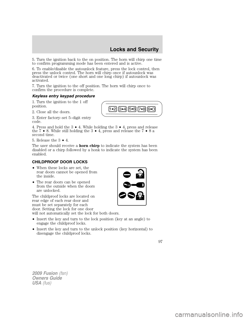
4. Press and hold the 3•4. While holding the 3•4, press and release
the 7•8. While still holding the 3•4, press and release the 7•8a
second time.
5. Release the 3•4.
The user should receive ahorn chirpto indicate the system has been
disabled or a chirp followed by a honk to indicate the system has been
enabled.
CHILDPROOF DOOR LOCKS
•When these locks are set, the
rear doors cannot be opened from
the inside.
•The rear doors can be opened
from the outside when the doors
are unlocked.
The childproof locks are located on
rear edge of each rear door and
must be set separately for each
door. Setting the lock for one door
will not automatically set the lock for both doors.
•Insert the key and turn to the lock position (key at an angle) to
engage the childproof locks.
•Insert the key and turn to the unlock position (key horizontal) to
disengage the childproof locks.
2009 Fusion(fsn)
Owners Guide
USA(fus)
Locks and Security
97
Page 98 of 312
INTERIOR LUGGAGE COMPARTMENT RELEASE
Your vehicle is equipped with a mechanical interior luggage compartment
release handle that provides a means of escape for children and adults in
the event they become locked inside the luggage compartment.
Adults are advised to familiarize themselves with the operation and
location of the release handle.
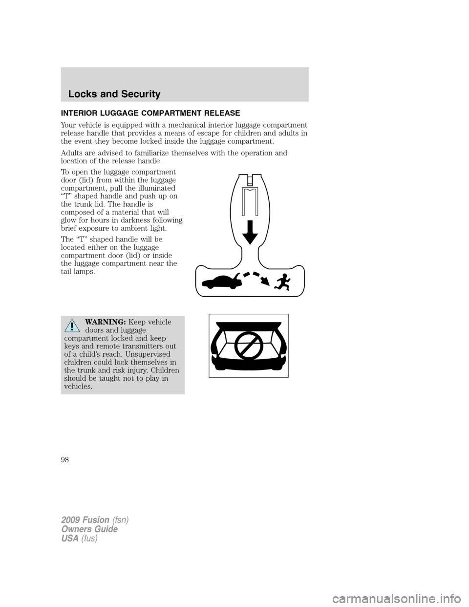
To open the luggage compartment
door (lid) from within the luggage
compartment, pull the illuminated
“T” shaped handle and push up on
the trunk lid. The handle is
composed of a material that will
glow for hours in darkness following
brief exposure to ambient light.
The “T” shaped handle will be
located either on the luggage
compartment door (lid) or inside
the luggage compartment near the
tail lamps.
WARNING:Keep vehicle
doors and luggage
compartment locked and keep
keys and remote transmitters out
of a child’s reach. Unsupervised
children could lock themselves in
the trunk and risk injury. Children
should be taught not to play in
vehicles.
2009 Fusion(fsn)
Owners Guide
USA(fus)
Locks and Security
98
Page 99 of 312
WARNING:Do not leave children, unreliable adults, or animals
unattended in the vehicle. On hot days, the temperature in the
trunk or vehicle interior can rise very quickly. Exposure of people or
animals to these high temperatures for even a short time can cause
death or serious heat-related injuries, including brain damage. Small
children are particularly at risk.
REMOTE ENTRY SYSTEM
The Integrated Keyhead Transmitter (IKT) complies with part 15 of the
FCC rules and with RSS-210 of Industry Canada. Operation is subject to
the following two conditions: (1) This device may not cause harmful
interference, and (2) This device must accept any interference received,
including interference that may cause undesired operation.
Changes or modifications not expressly approved by the party
responsible for compliance could void the user’s authority to
operate the equipment.
The typical operating range for your IKT is approximately 33 feet
(10 meters). A decrease in operating range could be caused by:
•weather conditions,
•nearby radio towers,
•structures around the vehicle, or
•other vehicles parked next to your vehicle.
2009 Fusion(fsn)
Owners Guide
USA(fus)
Locks and Security
99