2009 FORD F750 brakes
[x] Cancel search: brakesPage 117 of 276

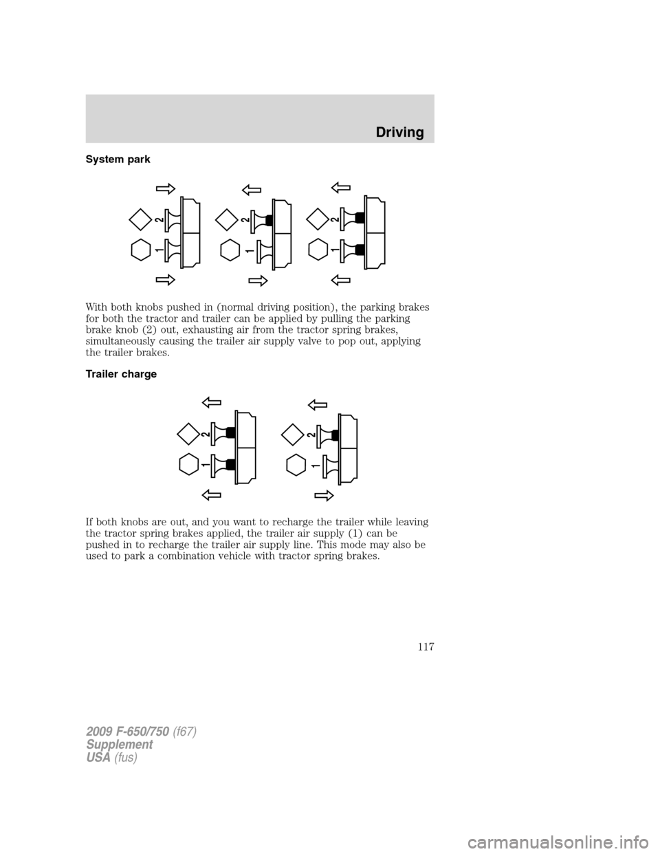
System park
With both knobs pushed in (normal driving position), the parking brakes
for both the tractor and trailer can be applied by pulling the parking
brake knob (2) out, exhausting air from the tractor spring brakes,
simultaneously causing the trailer air supply valve to pop out, applying
the trailer brakes.
Trailer charge
If both knobs are out, and you want to recharge the trailer while leaving
the tractor spring brakes applied, the trailer air supply (1) can be
pushed in to recharge the trailer air supply line. This mode may also be
used to park a combination vehicle with tractor spring brakes.
12
12
12
12 12
2009 F-650/750(f67)
Supplement
USA(fus)
Driving
117
Page 118 of 276

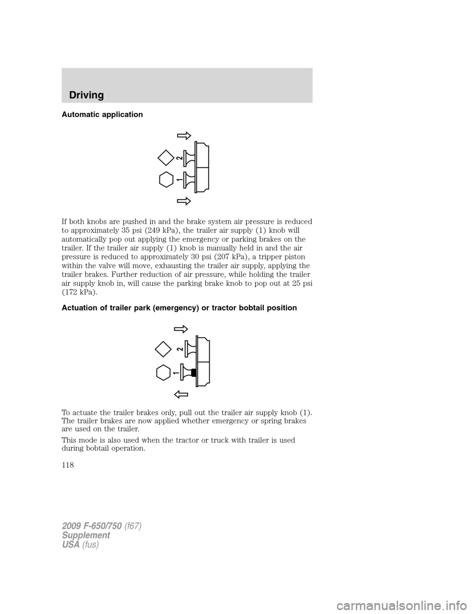
Automatic application
If both knobs are pushed in and the brake system air pressure is reduced
to approximately 35 psi (249 kPa), the trailer air supply (1) knob will
automatically pop out applying the emergency or parking brakes on the
trailer. If the trailer air supply (1) knob is manually held in and the air
pressure is reduced to approximately 30 psi (207 kPa), a tripper piston
within the valve will move, exhausting the trailer air supply, applying the
trailer brakes. Further reduction of air pressure, while holding the trailer
air supply knob in, will cause the parking brake knob to pop out at 25 psi
(172 kPa).
Actuation of trailer park (emergency) or tractor bobtail position
To actuate the trailer brakes only, pull out the trailer air supply knob (1).
The trailer brakes are now applied whether emergency or spring brakes
are used on the trailer.
This mode is also used when the tractor or truck with trailer is used
during bobtail operation.
12
1
2
2009 F-650/750(f67)
Supplement
USA(fus)
Driving
118
Page 119 of 276

ANTI-LOCK BRAKE SYSTEM (ABS)
A noise from the hydraulic pump motor and pulsation in the pedal may
be observed during ABS braking events. Pedal pulsation coupled with
noise while braking under panic conditions or on loose gravel, bumps,
wet or snowy roads is normal and indicates proper functioning of the
vehicle’s ABS. If the vehicle has continuous vibration or shudder in the
steering wheel while braking, the vehicle should be inspected by a
qualified service technician.
The ABS operates by detecting the
onset of wheel lockup during brake
applications and compensating for
this tendency. The wheels are
prevented from locking even when
the brakes are firmly applied. The
accompanying illustration depicts
the advantage of an ABS-equipped
vehicle (on bottom) to a non-ABS
equipped vehicle (on top) during hard braking with loss of front braking
traction.
ABS warning light
TheABSwarning light in the instrument cluster momentarily illuminates
when the ignition is turned on and the engine is off. If the light does not
illuminate momentarily at start up, remains on after the vehicle reaches
5–10 mph (8–16 km/h), or continues to flash, the ABS needs to be serviced.
With the ABS light on, the anti-lock brake system is disabled and normal
braking is still effective unless the brake warning light also remains
illuminated. (If your parking brake warning light illuminates, have your
vehicle serviced immediately.)
Using ABS
•In an emergency or when maximum efficiency from the ABS is
required, apply continuous full force on the brake. The ABS will be
activated immediately, thus allowing you to retain full steering control
of your vehicle and, providing there is sufficient space, will enable you
to avoid obstacles and bring the vehicle to a controlled stop.
•The ABS does not decrease the time necessary to apply the brakes or
always reduce stopping distance. Always leave enough room between
your vehicle and the vehicle in front of you to stop.
•We recommend that you familiarize yourself with this braking
technique. However, avoid taking any unnecessary risks.
2009 F-650/750(f67)
Supplement
USA(fus)
Driving
119
Page 120 of 276

TRACTION CONTROL™ (IF EQUIPPED)
Your vehicle may be equipped with a Traction Control™ system. This
system helps you maintain the stability and steerability of your vehicle,
especially on slippery road surfaces such as snow- or ice-covered roads
and gravel roads, by reducing engine power and/or selectively applying
the rear brakes. The system will allow your vehicle to make better use of
available traction in these conditions.
Note:The traction control system will not apply the brakes when the
vehicle speed is above 25 mph (40 km/h).
During Traction Control™ operation,
the traction control light in the
instrument cluster will flash rapidly
and the engine will not “rev-up”
when you push further on the
accelerator. This is normal system behavior and should be no reason for
concern. If the traction control light does not flash during a traction
control event or stays illuminated, the system is not functioning properly,
take your vehicle to your dealer for service.
When the Traction Control™ switch,
located on the instrument panel, is
activated standard Traction
Control™ will change to Off Road or
Mud/Snow traction mode, the
traction control light will be
illuminated and flash slowly. If a
traction event occurs, in either
mode the traction control light will
flash rapidly. The standard Traction
Control™ can be selected by
pushing the Traction Control™ switch again or will be automatically
selected at next ignition cycle.
If you should become stuck in snow or ice or on a very slippery road
surface, try switching to the Off Road or Mud/Snow Traction Control™
mode. This may allow excess wheel spin to “dig” the vehicle out and
enable a successful “rocking” maneuver.
2009 F-650/750(f67)
Supplement
USA(fus)
Driving
120
Page 122 of 276

Tractor-trailer connections
WARNING:To reduce the risk of personal injury, use extreme
caution when making brake and light connections. Inclement
weather and accumulated road contamination deposits on handhold
and stepping surfaces require extra care to avoid slip and falls. Provide
adequate lighting of working areas.
WARNING:Do not climb on the back of the tractor unless it
has been provided with a deck plate and handholds. Use a
three-point stance when climbing up and down from a deck plate. Do
not jump from the vehicle. Whenever possible, make all connections
while standing on the ground.
Connecting and disconnecting a trailer with air suspension
When connecting to a trailer:
•Press the lower portion of the switch and air will exhaust from the air
suspension system.
•After making the connection to the trailer, press the upper portion of
the switch, then raise the landing gear.
When disconnecting the trailer:
•Lower the landing gear, then press the lower portion of the switch.
•Disconnect the brake hoses, trailer-side and rear light connectors,
then pull the release lever on the fifth wheel.
The upper portion of the switch must be pressed before operating with a
trailer or operating in the bobtail mode.
Suspension conversions
It is not recommended, or approved, that suspension conversions be
performed. However, it is understood that, on occasion, aftermarket
add-on suspensions are installed by others on the truck chassis which
allow operator control for weight transfer from other axles (i.e., air lift
axles).
WARNING:When operating a loaded vehicle, the driver must
keep all adjustable axles on the ground at all times, supporting
their share of the vehicle’s load. Failure to do so can overload other
axles, tires, wheels, springs, steering components, brakes and frames,
resulting in early component failure, loss of vehicle control, possible
property damage and personal injury.
2009 F-650/750(f67)
Supplement
USA(fus)
Driving
122
Page 130 of 276

To go forward
With the engine idling, depress the clutch pedal and shift into 1 (First).
Engage the clutch while pressing the accelerator to start forward.
Operate the clutch and upshift as required by driving conditions.
To go backward
Reverse is obtained by putting the gearshift lever in R (Reverse) and
engaging the clutch while pressing lightly on the accelerator.
Operating the Spicer ES56-7B and ES066-7B 7-speed
transmissions
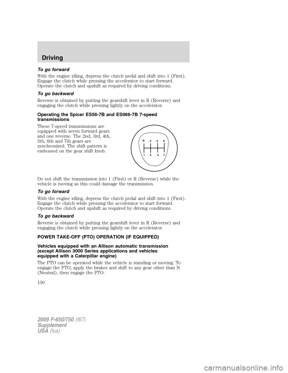
These 7-speed transmissions are
equipped with seven forward gears
and one reverse. The 2nd, 3rd, 4th,
5th, 6th and 7th gears are
synchronized. The shift pattern is
embossed on the gear shift knob.
Do not shift the transmission into 1 (First) or R (Reverse) while the
vehicle is moving as this could damage the transmission.
To go forward
With the engine idling, depress the clutch pedal and shift into 1 (First).
Engage the clutch while pressing the accelerator to start forward.
Operate the clutch and upshift as required by driving conditions.
To go backward
Reverse is obtained by putting the gearshift lever in R (Reverse) and
engaging the clutch while pressing lightly on the accelerator.
POWER TAKE-OFF (PTO) OPERATION (IF EQUIPPED)
Vehicles equipped with an Allison automatic transmission
(except Allison 3000 Series applications and vehicles
equipped with a Caterpillar engine)
The PTO can be operated while the vehicle is standing or moving. To
engage the PTO, apply the brakes and shift to any gear other than N
(Neutral), then engage the PTO.
2 4 6
3 5 71 R
2009 F-650/750(f67)
Supplement
USA(fus)
Driving
130
Page 131 of 276

If engagement is prevented by the gear teeth not meshing properly,
release the brakes and allow the vehicle to creep slightly or shift the
selector to N (Neutral) and then back into gear. The PTO should never
be engaged by clashing the gear teeth as this may damage the PTO unit
and the transmission PTO drive gear teeth. This could result in further
damage to the transmission and PTO.
PTO operation with vehicle stationary
Stop the vehicle, idle the engine and set the parking brake. Make sure
the gear selector is in any forward drive range, then engage the PTO.
After the PTO is engaged, move the range selector to N (Neutral).
Increase the engine speed until the desired power take-off operation
speed is obtained. To disengage the PTO after operation with the vehicle
standing, release the throttle, allow the drive equipment to come to a
stop, and then disengage the PTO.
WARNING:When the PTO is operated with the vehicle
stationary, the transmission must be placed in N (Neutral) with
the parking brake set. If the transmission is not in N (Neutral) and is
equipped with a remote throttle control, an increase in engine speed
can overpower the parking brake and cause the vehicle to move,
possibly resulting in personal injury and/or property damage.
PTO operation while vehicle is moving
After the PTO is engaged for driven vehicle operation, shift to the
desired range and drive the vehicle. The speed of the PTO, during this
period of operation, will always maintain direct relation to vehicle speed.
PTO speed will decrease in relation to vehicle (transmission output)
speed as shifts to a higher gear occur. When operating the PTO while the
vehicle is moving, the PTO may be disengaged whenever it is no longer
required. When there is no load on the PTO gear, it can be pulled out of
engagement.
Vehicles equipped with an Eaton UltraShift transmission
Refer to the operationTransmission Power Take Offsection of the
UltraShift Driver Instructions Manual.
Vehicles equipped with an Allison 3000 Series automatic
transmission
The PTO drive gear is engine-driven and provides direct engine power.
The PTO can be operated when the vehicle is either stationary or
moving.
2009 F-650/750(f67)
Supplement
USA(fus)
Driving
131
Page 133 of 276

Rear axles with locking or limited-slip differentials (if equipped)
If your vehicle is equipped with a locking or limited-slip differential, note
the following:
•Power will be transmitted to the opposite wheel should one of the
wheels begin to slip.
•Both wheels must be raised off the ground should it be necessary to
operate one wheel with the vehicle stationary.
WARNING:If both wheels are not raised off the ground, the
one wheel that is not raised may pull the vehicle off its support,
possibly resulting in personal injury
Driver-controlled differential lock
To prevent the vehicle from moving when servicing the wheels, tires or
brakes, turn the engine off and raise all drive wheels of the locker
differential axle. Axles equipped with NoSPIN Detroit Locker differentials
deliver power to both wheels even when only one wheel is on the ground.
WARNING:Failure to raise all drive wheels with this type of
differential could cause the vehicle to move unexpectedly,
resulting in property damage, personal injury or death.
Care should be taken to avoid sudden accelerations when both drive
wheels are on a slippery surface.
WARNING:Sudden accelerations on slippery surfaces could
cause the wheels to spin, the vehicle to turn sideways on a
crowned road surface or in a turn, possibly resulting in loss of vehicle
control and personal injury.
Some Dana/Spicer drive axles have a driver-controlled differential lock.
The differential lock can lock or unlock the differential when the vehicle
is moving or stopped. When extra traction is required, the differential
lock will provide full power to both axles.
When the differential is locked, the vehicle’s turning radius will increase
(vehicle will “under-steer”)
The differential can be locked or unlocked when the vehicle is moving at
a constant speed of less than 25 mph (40 km/h) and while the wheels
are not slipping. The differential must not be locked when the vehicle is
traveling down steep grades and traction is minimal.
2009 F-650/750(f67)
Supplement
USA(fus)
Driving
133