2009 FORD F650 maintenance
[x] Cancel search: maintenancePage 3 of 276

Maintenance and Specifications 171
Hood 179
Engine oil 182
Battery 182
Engine coolant 184
Fuel information 186
Wheel lug nut torque 212
Tire information 212
Lubricant specifications 220
Refill capacities 232
Scheduled Maintenance Guide 237
Index 272
All rights reserved. Reproduction by any means, electronic or mechanical
including photocopying, recording or by any information storage and retrieval
system or translation in whole or part is not permitted without written
authorization from Ford Motor Company. Ford may change the contents without
notice and without incurring obligation.
Copyright © 2008 Ford Motor Company
Table of Contents
3
2009 F-650/750(f67)
Supplement
USA(fus)
Page 11 of 276

To be sure your vehicle is ready to operate, conduct a pre-trip inspection
at the beginning of each work period. Follow the steps listed in this
section to ensure a proper vehicle inspection procedure. The pages in
this section may be produced locally and used on a regular basis.
VEHICLE INSPECTION INFORMATION
Note:Always make sure the parking brake is applied before starting the
engine.
Engine compartment (with engine stopped)
Engine oil level:Use the engine oil dipstick to verify that the
engine oil level is between the ADD and
OPERATING RANGE marks.
Engine coolant
level:Look through the plastic reservoir or the clear
sight glass on the reservoir, depending upon
vehicle equipment, and make sure the fluid is
within the minimum and maximum fluid level
range as marked on the reservoir.Do not
remove pressure cap until the coolant has
cooled.
Power steering fluid:Verify that the fluid level is in the proper
operating range. Refer toPower steering
fluidin theMaintenance and Specifications
chapter.
Brake fluid (master
cylinder):Remove the master cylinder caps and inspect
the fluid level. The full mark is at the bottom
of the opening of the fluid ports.
Hydraulic clutch
fluid:Check for adequate amount of hydraulic clutch
fluid. Fluid level should be at the step of the
reservoir; refer toClutch fluid/linkage
adjustmentsin theMaintenance and
Specificationschapter.
Belts (Fan,
alternator, water
pump and A/C
compressor):Check for glazing, fraying or cracking. There
should be no more than five - seven cracks per
rib per inch (2.5 cm).
2009 F-650/750(f67)
Supplement
USA(fus)
Vehicle Inspection Guide
11
Page 15 of 276

Engine starting (parking brake applied)
Air brake check:Check the air brakes in the following manner
(Chock the wheels, if necessary. Push in the
parking brake and on tractors, also push in the
tractor parking brake knob):
1. Check the that air compressor or governor
cut-out pressure is approximately 120 psi
(827 kPa).
2. Turn off the engine and turn the key back
to ON, without starting the engine.
3. Without the brake pedal applied, note the
air pressure drop for one minute. It should be
less than 2 psi (14 kPa) for single vehicle and
3 psi (21 kPa) for combination vehicles.
4. Depress and hold the brake pedal with
90 psi (621 kPa) or more and make sure there
is no more than a 3 psi (21 kPa) per minute
leak; for combination vehicles, no more than
4 psi (28 kPa) per minute.
5. Pump the brake pedal to deplete the system
of air pressure. The warning light and chime
should activate at 57 psi (393 kPa).
6. Pump the brake pedal and make sure the
parking brake and trailer parking brake knobs
pop out at 20 psi (138 kPa) or higher.
Automatic
transmission fluid:With the engine idling at normal operating
temperature and the parking brake applied,
check the automatic transmission fluid. If fluid
needs to be added, place the transmission in
the appropriate gear as specified in the
transmission operator’s manual and refer to
Transmission fluidin theMaintenance and
Specificationschapter.
2009 F-650/750(f67)
Supplement
USA(fus)
Vehicle Inspection Guide
15
Page 27 of 276

Charging system:Illuminates when
the battery is not charging properly.
Diesel particulate filter
(Cummins engines only):
Illuminates if the soot in the DPF
has reached a level where it
requires operator assistance. Refer
toDiesel Particulate Filterin the
Maintenance and Specificationschapter and your engine operator’s
manual, for more details.
Turn signal:Illuminates when the
left or right turn signal or the
hazard lights are turned on. If the indicators stay on or flash faster,
check for a burned out bulb.
High beams:Illuminates when the
high beam headlamps are turned on.
Safety belt warning chime:Sounds when the key is in the ignition and
the driver’s safety belt is not fastened.
Key-in-ignition warning chime:Sounds when the key is left in the
ignition in the OFF/LOCK or ACC position and the driver’s door is
opened.
Headlamps on warning chime:Sounds when the headlamps or parking
lamps are on, the ignition is off (and the key is not in the ignition) and
the driver’s door is opened.
2009 F-650/750(f67)
Supplement
USA(fus)
Instrument Cluster
27
Page 74 of 276

WARNING:Do not use extensions to change the fit of the
shoulder belt across the torso.
Safety belt maintenance
Inspect the safety belt systems periodically to make sure they work
properly and are not damaged. Inspect the safety belts to make sure
there are no nicks, tears or cuts. Replace if necessary. All safety belt
assemblies, including retractors, buckles, front seat belt buckle
assemblies, buckle support assemblies (slide bar-if equipped), shoulder
belt height adjusters (if equipped), shoulder belt guide on seatback (if
equipped), child safety seat tether anchors, and attaching hardware,
should be inspected after a collision.
WARNING:Ford Motor Company recommends that all safety
belt assemblies used in vehicles involved in a collision be
inspected for proper function and replaced, if necessary. Safety belt
assemblies not in use during a collision should also be inspected and
replaced if either damage or improper operation is noted.
WARNING:Failure to inspect and if necessary replace the
safety belt assembly under the above conditions could result in
severe personal injuries in the event of a collision.
Refer toInteriorin theCleaningchapter.
Safety belt warning light and indicator chime
The safety belt warning light illuminates in the instrument cluster and a
chime sounds to remind the occupants to fasten their safety belts.
2009 F-650/750(f67)
Supplement
USA(fus)
Seating and Safety Restraints
74
Page 95 of 276

Note:Idling in cold weather will not heat the engine to its normal
operating temperature. Long periods of idling in cold weather can cause
a build-up of heavy deposits of carbon and rust on valve stems causing
them to stick which, in turn, can cause valvetrain damage.
Winter fronts
The use of winter fronts, or other air-restrictive devices mounted in front
of the radiator on vehicles with chassis-mounted charge air coolers, are
not recommended unless extremely cold weather conditions exist. Air
flow restriction can cause high exhaust temperatures, power loss,
excessive fan usage and a reduction in fuel economy. If you must use a
winter front, the device should have a permanent opening of at least 120
sq in. (774 sq. cm) directly in line with the fan hub.
Hot weather operation
•Keep the engine cooling system filled with a clean, permanent coolant
solution to protect against damage from overheating.
•Fill the fuel tank at the end of daily operation to prevent condensation
in the fuel system.
•Keep external surfaces of the engine, radiator, charge air cooler, A/C
condenser and accessories clean to avoid dirt build-up.
Above normal coolant temperatures could be experienced while driving
in a transmission gear ratio which lugs the engine. To correct this
problem, engine speed should be increased by downshifting in to the
next lower gear to increase engine RPM.
Starting a turbocharged engine with the vehicle on a steep grade
When starting a diesel engine when the loaded vehicle is on a grade, the
engine RPM will start to fall slightly when the clutch is engaged; do not
disengage the clutch and try to increase engine RPM as this may damage
driveline components. The engine will recover as the vehicle begins
moving.
Engine shutdown
Allow the engine to idle for three to five minutes before shutting it
down. The larger the engine, the greater the need for this idling period.
However, do not let the engine idle for more than 10 minutes.
Restarting after running out of fuel
The fuel system may need to be purged of air, refer toRunning out of
fuelin theMaintenance and Specificationschapter.
2009 F-650/750(f67)
Supplement
USA(fus)
Driving
95
Page 98 of 276

•Within the final 30 seconds, the timer can be reset by:
1. changing the position of the accelerator pedal, or
2. changing the brake pedal, clutch pedal, or park brake from engaged
to disengaged or from disengaged to engaged.
•When the timer reaches zero, the engine will shut down.
•In this event, the key remains in the ON (Run) position, and power
continues to be supplied to the accessories.
Battery power may be drained if the key is left in the ON (Run)
position without the engine running.
Note:The engine idle shutdown timer will not start if:
•The engine is operating in power take-off (PTO) mode.
•The engine coolant temperature is below 60° F (16° C).
•The exhaust emission control system is regenerating the diesel
particulate filter (DPF).
ENGINE AUTOMATIC SHUTDOWN WARNING LIGHT OR CHIME
(IF EQUIPPED)
Your vehicle may be equipped with an automatic shutdown feature that
stops the engine in the event of high coolant temperature, low engine oil
pressure, high diesel particulate filter soot loading or low engine coolant
level. A warning light in the instrument cluster and a warning chime will
indicate high engine coolant temperature, low engine oil pressure or the
need to have the diesel particulate filter cleaned or serviced. If the
engine coolant temperature becomes too high, engine oil pressure too
low or the diesel particulate filter too restricted, the engine will
automatically shut down.
If the engine shuts down, it can be restarted and operated for
30 seconds at a time or until the problem is corrected. Do not attempt to
use this restarting feature to drive the vehicle very far as serious engine
damage could result.
WARNING:In the event of engine shutdown, make sure the
vehicle is safely off the road and the problem is remedied prior
to returning to the road. Failure to remove the vehicle from the road
could result in an accident, causing serious injury or death.
GENERAL BRAKE INFORMATION
All standard equipment brakes are designed to be self-adjusting.
Automatic adjustment, when required, occurs whenever the brakes are
applied and released during forward or reverse operation. Refer to the
Scheduled Maintenance Guidechapter for scheduled maintenance.
2009 F-650/750(f67)
Supplement
USA(fus)
Driving
98
Page 107 of 276

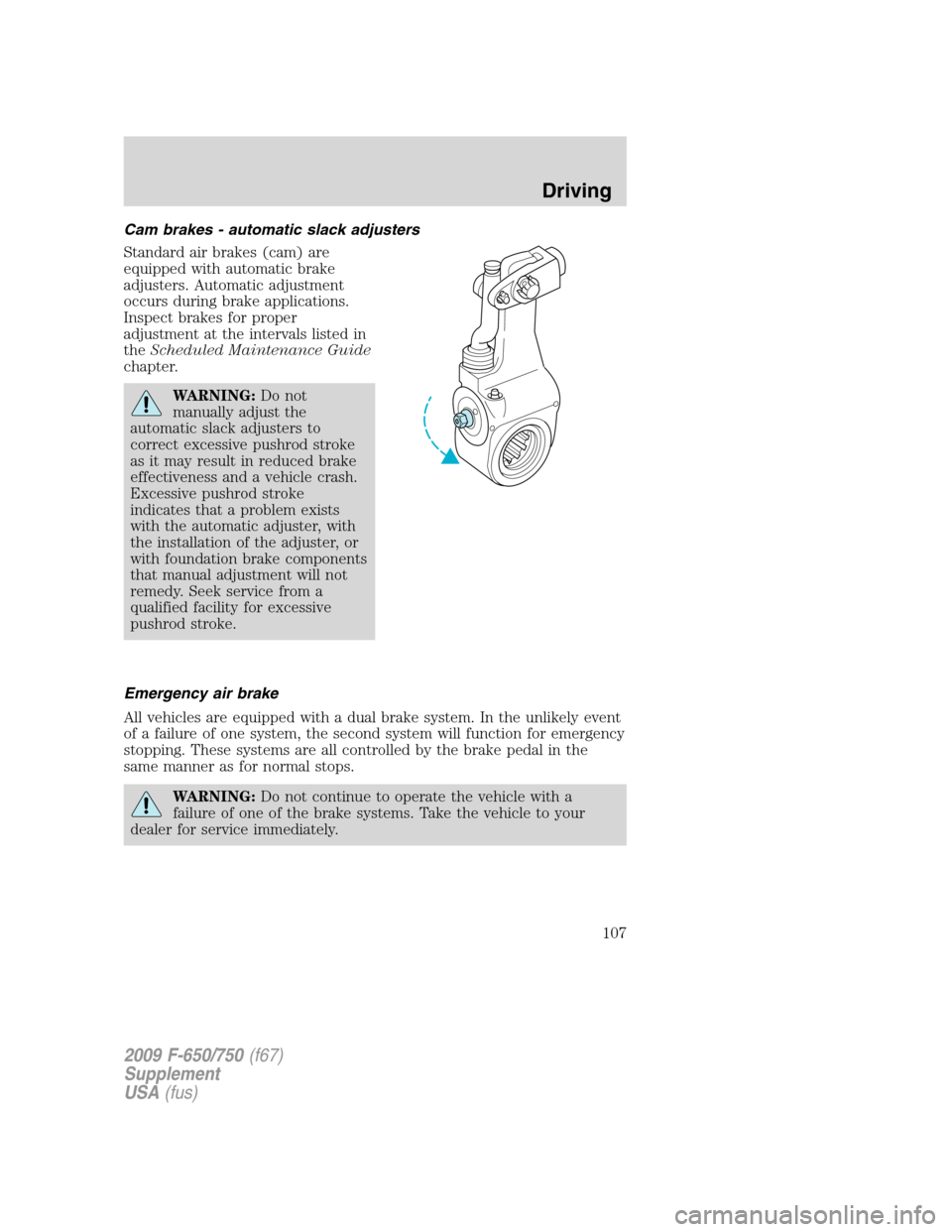
Cam brakes - automatic slack adjusters
Standard air brakes (cam) are
equipped with automatic brake
adjusters. Automatic adjustment
occurs during brake applications.
Inspect brakes for proper
adjustment at the intervals listed in
theScheduled Maintenance Guide
chapter.
WARNING:Do not
manually adjust the
automatic slack adjusters to
correct excessive pushrod stroke
as it may result in reduced brake
effectiveness and a vehicle crash.
Excessive pushrod stroke
indicates that a problem exists
with the automatic adjuster, with
the installation of the adjuster, or
with foundation brake components
that manual adjustment will not
remedy. Seek service from a
qualified facility for excessive
pushrod stroke.
Emergency air brake
All vehicles are equipped with a dual brake system. In the unlikely event
of a failure of one system, the second system will function for emergency
stopping. These systems are all controlled by the brake pedal in the
same manner as for normal stops.
WARNING:Do not continue to operate the vehicle with a
failure of one of the brake systems. Take the vehicle to your
dealer for service immediately.
2009 F-650/750(f67)
Supplement
USA(fus)
Driving
107