Page 43 of 271

PANEL DIMMER CONTROL
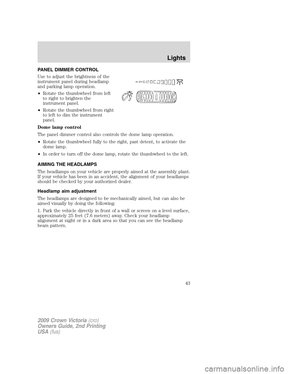
Use to adjust the brightness of the
instrument panel during headlamp
and parking lamp operation.
•Rotate the thumbwheel from left
to right to brighten the
instrument panel.
•Rotate the thumbwheel from right
to left to dim the instrument
panel.
Dome lamp control
The panel dimmer control also controls the dome lamp operation.
•Rotate the thumbwheel fully to the right, past detent, to activate the
dome lamp.
•In order to turn off the dome lamp, rotate the thumbwheel to the left.
AIMING THE HEADLAMPS
The headlamps on your vehicle are properly aimed at the assembly plant.
If your vehicle has been in an accident, the alignment of your headlamps
should be checked by your authorized dealer.
Headlamp aim adjustment
The headlamps are designed to be mechanically aimed, but can also be
aimed visually by doing the following:
1. Park the vehicle directly in front of a wall or screen on a level surface,
approximately 25 feet (7.6 meters) away. Check your headlamp
alignment at night or in a dark area so that you can see the headlamp
beam pattern.
2009 Crown Victoria(cro)
Owners Guide, 2nd Printing
USA(fus)
Lights
43
Page 44 of 271

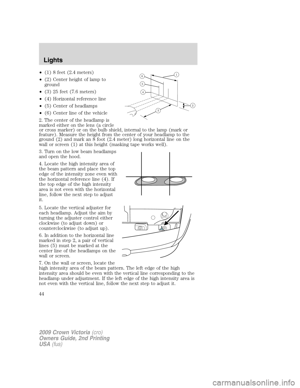
•(1) 8 feet (2.4 meters)
•(2) Center height of lamp to
ground
•(3) 25 feet (7.6 meters)
•(4) Horizontal reference line
•(5) Center of headlamps
•(6) Center line of the vehicle
2. The center of the headlamp is
marked either on the lens (a circle
or cross marker) or on the bulb shield, internal to the lamp (mark or
feature). Measure the height from the center of your headlamp to the
ground (2) and mark an 8 foot (2.4 meter) long horizontal line on the
wall or screen (1) at this height (masking tape works well).
3. Turn on the low beam headlamps
and open the hood.
4. Locate the high intensity area of
the beam pattern and place the top
edge of the intensity zone even with
the horizontal reference line (4). If
the top edge of the high intensity
area is not even with the horizontal
line, follow the next step to adjust
it.
5. Locate the vertical adjuster for
each headlamp. Adjust the aim by
turning the adjuster control either
clockwise (to adjust down) or
counterclockwise (to adjust up).
6. In addition to the horizontal line
marked in step 2, a pair of vertical
lines (5) must be marked at the
center line of the headlamps on the
wall or screen.
7. On the wall or screen, locate the
high intensity area of the beam pattern. The left edge of the high
intensity area should be even with the vertical line corresponding to the
headlamp under adjustment. If the left edge of the high intensity area is
not even with the vertical line, follow the next step to adjust it.
2009 Crown Victoria(cro)
Owners Guide, 2nd Printing
USA(fus)
Lights
44
Page 190 of 271

Fuse/Relay
LocationFuse Amp
RatingProtected Circuits
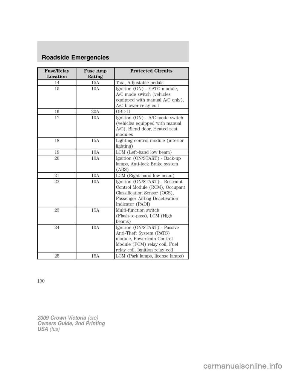
14 15A Taxi, Adjustable pedals
15 10A Ignition (ON) - EATC module,
A/C mode switch (vehicles
equipped with manual A/C only),
A/C blower relay coil
16 20A OBD II
17 10A Ignition (ON) - A/C mode switch
(vehicles equipped with manual
A/C), Blend door, Heated seat
modules
18 15A Lighting control module (interior
lighting)
19 10A LCM (Left-hand low beam)
20 10A Ignition (ON/START) - Back-up
lamps, Anti-lock Brake system
(ABS)
21 10A LCM (Right-hand low beam)
22 10A Ignition (ON/START) - Restraint
Control Module (RCM), Occupant
Classification Sensor (OCS),
Passenger Airbag Deactivation
Indicator (PADI)
23 15A Multi-function switch
(Flash-to-pass), LCM (High
beams)
24 10A Ignition (ON/START) - Passive
Anti-Theft System (PATS)
module, Powertrain Control
Module (PCM) relay coil, Fuel
relay coil, Ignition relay coil
25 15A LCM (Park lamps, license lamps)
2009 Crown Victoria(cro)
Owners Guide, 2nd Printing
USA(fus)
Roadside Emergencies
190