2009 FIAT GRANDE PUNTO start stop button
[x] Cancel search: start stop buttonPage 24 of 210

23
SAFETY
STARTING
AND DRIVING
WARNING
LIGHTS AND
MESSAGES
IN AN
EMERGENCY
SERVICE
AND CARE
TECHNICAL
SPECIFICATIONS
INDEX
CONTROLS
AND DEVICES
Day
YearMonth
Deutsch
Português
English
Español
Français
Italiano
Nederland
Polski Example:
fig. 20 Example:
On the standard screen, briefly press MENU ESC
to start browsing. Press +or –to browse within
the menu.
NBFor safety reasons, only the short menu may be
accessed while the car is moving (“Speed Beep” set-
ting). Stop the car to access the full menu.
F0M1038g
MENU ESC
brief press
of the button+
–
+
–
– +
– –
– +
+
++ ––––
++ – –
+ +
–
EXIT MENU SPEED BEEP
SET TIME
SET DATE
SEE RADIO
AUTOCLOSE
DISTANCE UNIT
LANGUAGE ALERT VOLUME BUTTON VOLUMESERVICE PASSENGER BAG
–+
TRIP DATA B
MENU ESC
brief press
of the button
+
001-032 ACTUAL 1ed EN.qxd 28-08-2009 13:41 Pagina 23
Page 41 of 210

40
SAFETY
STARTING
AND DRIVING
WARNING
LIGHTS AND
MESSAGES
IN AN
EMERGENCY
SERVICE
AND CARE
TECHNICAL
SPECIFICATIONS
INDEX
CONTROLS
AND DEVICES
FRONT FAST DEMISTING/
DEFROSTING (WINDSCREEN
AND SIDE WINDOWS)
Proceed as follows:
❒turn knob Ato red section;
❒turn air internal recirculation off by
pressing button D(button LED off);
❒turn knob Cto -;
❒turn knob Bto 4 -(max. fan speed).
After demisting/defrosting, operate the
controls to restore the required comfort
conditions.Window demisting
In the event of considerable external
moisture and/or rain and/or large differ-
ences in temperature inside and outside
the passenger compartment, perform the
following preventive window demisting
procedure:
❒turn knob Ato red section;
❒turn air internal recirculation off by
pressing button D(button LED off);
❒turn knob Cto -or to ®if the win-
dows do not demist;
❒turn knob Bto 2ndspeed.HEATED REAR WINDSCREEN
AND WING MIRRORS
DEMISTING/DEFROSTING fig. 35
(for versions/markets where provided)
Press button Ato activate; when this func-
tion is on, the button LED lights up.
This function is timed and will turn off au-
tomatically after 20 minutes. Press Aagain
to switch it off before 20 minutes elapses.
IMPORTANT Do not apply stickers on
the inside of the rear window over the
heating filaments to avoid damage that
might cause it to stop working properly.
fig. 35F0M0036m
033-071 ACTUAL 1ed EN 28-08-2009 13:43 Pagina 40
Page 46 of 210

45
SAFETY
STARTING
AND DRIVING
WARNING
LIGHTS AND
MESSAGES
IN AN
EMERGENCY
SERVICE
AND CARE
TECHNICAL
SPECIFICATIONS
INDEX
CONTROLS
AND DEVICES
Window demisting
In the event of considerable external
moisture and/or rain and/or large differ-
ences in temperature inside and outside
the passenger compartment, perform the
following preventive window demisting
procedure:
❒turn knob Ato red section;
❒turn air internal recirculation off by
pressing button Dso the button LED
goes out;
❒turn knob Cto -or to ®if the win-
dows do not demist;
❒turn knob Bto 2ndspeed.
IMPORTANT The climate control system
is very useful to prevent the windows
misting up in the presence of high humid-
ity since it dries the air introduced into the
passenger compartment.HEATED REAR WINDSCREEN
AND WING MIRRORS
DEMISTING/DEFROSTING fig. 38
(for versions/markets where provided)
Press button Ato activate; when this func-
tion is on, the button LED lights up.
This function is timed and will turn off au-
tomatically after 20 minutes. Press Aagain
to switch it off before 20 minutes elapses.
IMPORTANT Do not apply stickers on
the inside of the rear window over the
heating filaments to avoid damage that
might cause it to stop working properly.
fig. 38F0M0038m
After demisting/defrosting, operate the
controls to restore the required comfort
conditions.
IMPORTANT The climate control system
is very useful for faster demisting because
it dries the air. Adjust the controls as de-
scribed above and press button Eto
switch the climate control system on; the
LED on the button will light up.
033-071 ACTUAL 1ed EN 28-08-2009 13:43 Pagina 45
Page 55 of 210

54
SAFETY
STARTING
AND DRIVING
WARNING
LIGHTS AND
MESSAGES
IN AN
EMERGENCY
SERVICE
AND CARE
TECHNICAL
SPECIFICATIONS
INDEX
CONTROLS
AND DEVICES
HEATED REAR WINDOW fig. 49
Press button Ato activate. The device will
be switched off automatically after ap-
proximately 20 minutes.
fig. 49F0M0036m
PARKING LIGHTS
These lights can be turned on, only with
the key turned to STOPor removed, by
turning the twist switch on the left stalk
first to Oand then to
6or 2.
The
3light on the instrument panel
comes on.
DUALDRIVE ELECTRIC POWER
STEERING SYSTEM fig. 48
Press button A to activate the “CITY”
function (see the “Electric power steering
system” paragraph in this section). When
the function is active, the word CITYis
lit up on the instrument panel. Press the
button again to deactivate the function.
fig. 48F0M0073m
REAR FOG LAMPS fig. 47
Press button 4to turn these lights on
with the dipped beam headlights or the
front fog lights (for versions/markets
where provided) switched on.
The 4light on the instrument panel will
come on.
Press the button again to turn the lights
off or turn off the dipped beam headlights
and/or the front fog lights (for versions/
markets where provided).
The use of rear fog lamps is governed by
the highway code of the country you are
in. Keep to the rules.
fig. 47F0M0071m
033-071 ACTUAL 1ed EN 28-08-2009 13:44 Pagina 54
Page 56 of 210

55
SAFETY
STARTING
AND DRIVING
WARNING
LIGHTS AND
MESSAGES
IN AN
EMERGENCY
SERVICE
AND CARE
TECHNICAL
SPECIFICATIONS
INDEX
CONTROLS
AND DEVICES
Door unlocking in the event of
a crash
If the fuel cut-off switch trips following an
accident, the doors will be automatically
unlocked to allow access to the passenger
compartment and the ceiling lights will be
switched on at the same time. The doors
can always be opened from the inside of
the car by using the appropriate controls.
if no fuel leakage is found and the car is
roadworthy, ensure the correct operation
of the vehicle by adhering to the following
instructions. DOOR LOCKING fig. 50
To lock all doors at the same time, press
button A, located on the central console
control panel, regardless of the position
of the ignition key.FUEL CUT-OFF SYSTEM
This system triggers after a collision and
activates the following:
❒cut-off of fuel supply with consequent
switching off of the engine;
❒automatic door unlocking;
❒switching on of all interior lights.
When the system has been triggered, the
message “Fuel cut off, see handbook” is
displayed.
Carefully check the car for fuel leaks, for
instance in the engine compartment, un-
der the car or near the tank area.
After a crash, turn the key to STOP to
avoid draining the battery.fig. 50F0M0013m
If, after a crash, you smell fu-
el or notice leaks from the
fuel system, do not reactivate the sys-
tem to avoid the risk of fire.
WARNING
033-071 ACTUAL 1ed EN 28-08-2009 13:44 Pagina 55
Page 61 of 210

60
SAFETY
STARTING
AND DRIVING
WARNING
LIGHTS AND
MESSAGES
IN AN
EMERGENCY
SERVICE
AND CARE
TECHNICAL
SPECIFICATIONS
INDEX
CONTROLS
AND DEVICES
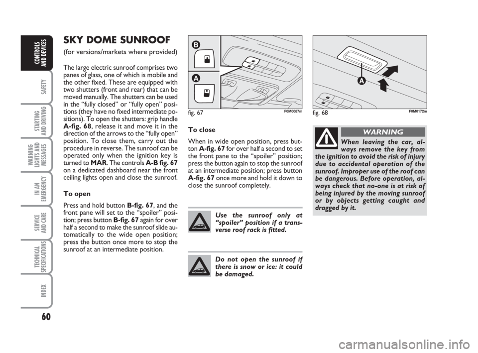
SKY DOME SUNROOF
(for versions/markets where provided)
The large electric sunroof comprises two
panes of glass, one of which is mobile and
the other fixed. These are equipped with
two shutters (front and rear) that can be
moved manually. The shutters can be used
in the “fully closed” or “fully open” posi-
tions (they have no fixed intermediate po-
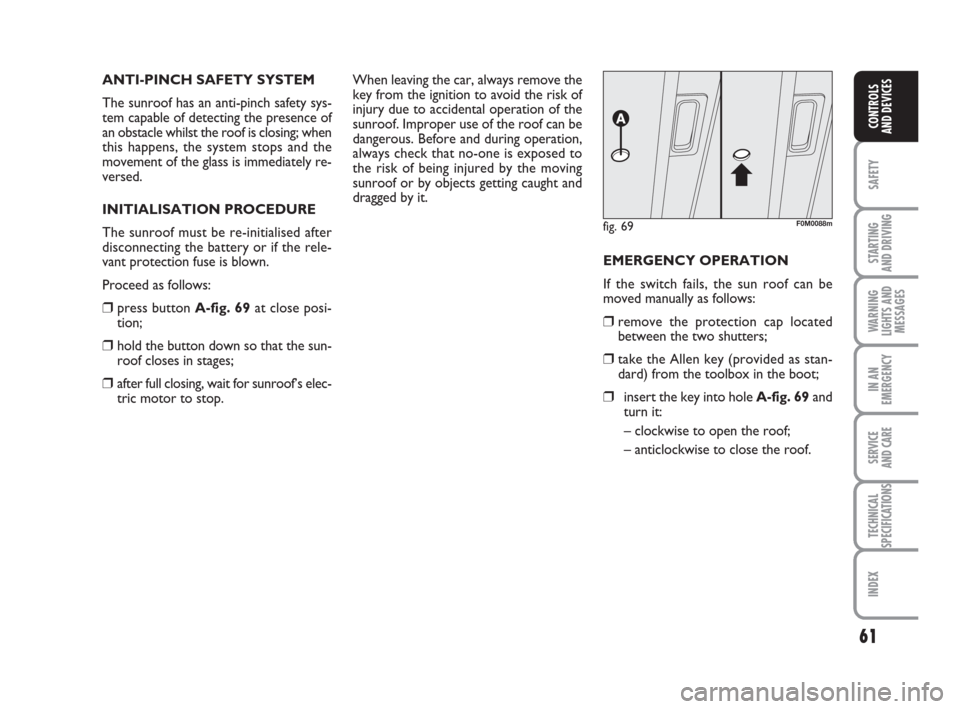
sitions). To open the shutters: grip handle
A-fig. 68, release it and move it in the
direction of the arrows to the “fully open”
position. To close them, carry out the
procedure in reverse. The sunroof can be
operated only when the ignition key is
turned to MAR. The controls A-B fig. 67
on a dedicated dashboard near the front
ceiling lights open and close the sunroof.
To open
Press and hold button B-fig. 67, and the
front pane will set to the “spoiler” posi-
tion; press button B-fig. 67 again for over
half a second to make the sunroof slide au-
tomatically to the wide open position;
press the button once more to stop the
sunroof at an intermediate position.To close
When in wide open position, press but-
ton A-fig. 67for over half a second to set
the front pane to the “spoiler” position;
press the button again to stop the sunroof
at an intermediate position; press button
A-fig. 67once more and hold it down to
close the sunroof completely.
fig. 67
A
B
F0M0087m
Use the sunroof only at
“spoiler” position if a trans-
verse roof rack is fitted.
Do not open the sunroof if
there is snow or ice: it could
be damaged.
When leaving the car, al-
ways remove the key from
the ignition to avoid the risk of injury
due to accidental operation of the
sunroof. Improper use of the roof can
be dangerous. Before operation, al-
ways check that no-one is at risk of
being injured by the moving sunroof
or by objects getting caught and
dragged by it.
WARNING
fig. 68F0M0172m
033-071 ACTUAL 1ed EN 28-08-2009 13:44 Pagina 60
Page 62 of 210

61
SAFETY
STARTING
AND DRIVING
WARNING
LIGHTS AND
MESSAGES
IN AN
EMERGENCY
SERVICE
AND CARE
TECHNICAL
SPECIFICATIONS
INDEX
CONTROLS
AND DEVICES
ANTI-PINCH SAFETY SYSTEM
The sunroof has an anti-pinch safety sys-
tem capable of detecting the presence of
an obstacle whilst the roof is closing; when
this happens, the system stops and the
movement of the glass is immediately re-
versed.
INITIALISATION PROCEDURE
The sunroof must be re-initialised after
disconnecting the battery or if the rele-
vant protection fuse is blown.
Proceed as follows:
❒press button A-fig. 69at close posi-
tion;
❒hold the button down so that the sun-
roof closes in stages;
❒after full closing, wait for sunroof’s elec-
tric motor to stop.When leaving the car, always remove the
key from the ignition to avoid the risk of
injury due to accidental operation of the
sunroof. Improper use of the roof can be
dangerous. Before and during operation,
always check that no-one is exposed to
the risk of being injured by the moving
sunroof or by objects getting caught and
dragged by it.
EMERGENCY OPERATION
If the switch fails, the sun roof can be
moved manually as follows:
❒remove the protection cap located
between the two shutters;
❒take the Allen key (provided as stan-
dard) from the toolbox in the boot;
❒insert the key into hole A-fig. 69and
turn it:
– clockwise to open the roof;
– anticlockwise to close the roof.
fig. 69F0M0088m
033-071 ACTUAL 1ed EN 28-08-2009 13:44 Pagina 61
Page 66 of 210

65
SAFETY
STARTING
AND DRIVING
WARNING
LIGHTS AND
MESSAGES
IN AN
EMERGENCY
SERVICE
AND CARE
TECHNICAL
SPECIFICATIONS
INDEX
CONTROLS
AND DEVICES
WINDOWS
ELECTRIC
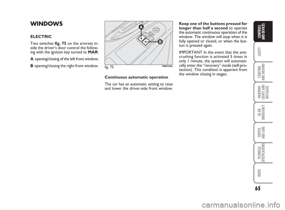
Two switches fig. 75on the armrest in-
side the driver’s door control the follow-
ing with the ignition key turned to MAR:
Aopening/closing of the left front window;
B opening/closing the right front window.Keep one of the buttons pressed for
longer than half a secondto operate
the automatic continuous operation of the
window. The window will stop when it is
fully opened or closed, or when the but-
ton is pressed again.
IMPORTANT In the event that the anti-
crushing function is activated 5 times in
only 1 minute, the system will automati-
cally enter the “recovery” mode (self-pro-
tection). This condition is apparent from
the window closing in stages.
fig. 75F0M0136m
Continuous automatic operation
The car has an automatic setting to raise
and lower the driver-side front window.
033-071 ACTUAL 1ed EN 28-08-2009 13:44 Pagina 65