2009 FIAT DUCATO side lights
[x] Cancel search: side lightsPage 97 of 282

96
SAFETY
DEVICES
CORRECT USE
OF THE
VEHICLE
WARNING
LIGHTS AND
MESSAGES
IN AN
EMERGENCY
VEHICLE
MAINTENANCE
TECHNICAL
SPECIFICATIONS
INDEX
DASHBOARD
AND CONTROLS
fig. 114F0N0129mfig. 115F0N0130mfig. 116F0N0131m
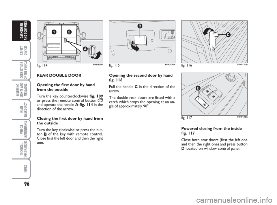
REAR DOUBLE DOOR
Opening the first door by hand
from the outside
Turn the key counterclockwise fig. 109
or press the remote control button ∞
and operate the handleA-fig. 114in the
direction of the arrow.
Closing the first door by hand from
the outside
Turn the key clockwise or press the but-
ton Áof the key with remote control.
Close first the left door and then the right
one. Opening the second door by hand
fig. 116
Pull the handle Cin the direction of the
arrow.
The double rear doors are fitted with a
catch which stops the opening at an an-
gle of approximately 90°.
Powered closing from the inside
fig. 117
Close both rear doors (first the left one
and then the right one) and press button
Dlocated on window control panel.
fig. 117F0N0132m
Page 99 of 282

98
SAFETY
DEVICES
CORRECT USE
OF THE
VEHICLE
WARNING
LIGHTS AND
MESSAGES
IN AN
EMERGENCY
VEHICLE
MAINTENANCE
TECHNICAL
SPECIFICATIONS
INDEX
DASHBOARD
AND CONTROLS
Automatic continuous operation
All versions are equipped with automatic
raising and lowering of the front, driver's
side window.
Automatic continuous operation activates
by pressing one of the control switches
for over half a second. The window will
stop when it is completely open or when
pressing the button again.
IMPORTANT With ignition key at STOP
or removed, the power windows remain
activated for about 3 minutes and are de-
activated immediately the moment a door
is opened.
fig. 119F0N0062m
Improper use of the power
windows can be dangerous.
Before and during its operation en-
sure that any passengers are not at
risk from the moving glass either by
personal objects getting caught in the
mechanism or by being injured by it
directly. Always remove the ignition
key when getting out of the vehicle to
prevent the power windows being op-
erated accidentally and constituting
a danger to the passengers in the ve-
hicle.
WARNINGBONNET
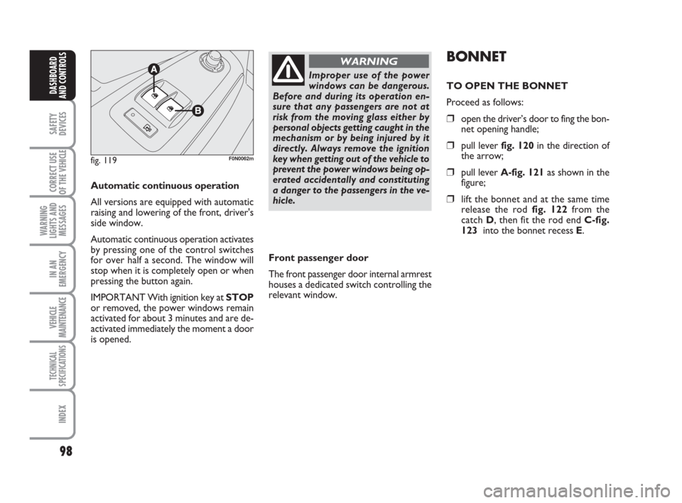
TO OPEN THE BONNET
Proceed as follows:
❒open the driver’s door to fing the bon-
net opening handle;
❒pull lever fig. 120in the direction of
the arrow;
❒pull lever A-fig. 121as shown in the
figure;
❒lift the bonnet and at the same time
release the rod fig. 122 from the
catch D, then fit the rod end C-fig.
123 into the bonnet recess E.
Front passenger door
The front passenger door internal armrest
houses a dedicated switch controlling the
relevant window.
Page 101 of 282

Distribute the load evenly
and when driving, bear in
mind the increased sensitivity of the
vehicle to side wind.
100
SAFETY
DEVICES
CORRECT USE
OF THE
VEHICLE
WARNING
LIGHTS AND
MESSAGES
IN AN
EMERGENCY
VEHICLE
MAINTENANCE
TECHNICAL
SPECIFICATIONS
INDEX
DASHBOARD
AND CONTROLS
ROOF RACK/SKI RACK
To fit roof racks/ski racks, with presetting
for versions H1 and H2, use the proper
pins set at roof edges fig. 124.
Long wheelbase vehicles are fitted with 8
pins; short or medium wheelbase vehicles
are fitted with 6 pins; extra-long wheel-
base vehicles are fitted with 10 pins.
After travelling a few kilo-
metres, check that the cou-
pling fastening screws are tight.
WARNING
Strictly comply with current
law regulations concerning
max. overall dimensions.
Never exceed the permitted
weight (see section “Techni-
cal specifications”).
IMPORTANT Strictly follow the installa-
tion instructions contained in the kit. In-
stallation hall be carried out by skilled per-
sonnel.
fig. 124F0N0138m
WARNING
Page 104 of 282

103
SAFETY
DEVICES
CORRECT USE
OF THE
VEHICLE
WARNING
LIGHTS AND
MESSAGES
IN AN
EMERGENCY
VEHICLE
MAINTENANCE
TECHNICAL
SPECIFICATIONS
INDEX
DASHBOARD
AND CONTROLS
BRAKE ASSIST
(emergency braking assistance
integral with ESP) (where provided)
The system, which cannot be cut out, rec-
ognizes emergency braking (on the ground
of the brake pedal operation speed) and
considerably increases the pressure in the
brake circuit.
Brake Assist is deactivated on the versions
equipped with ESP, in the event of ESP sys-
tem failure (indicated by warning light
áswitching on together with the message
on the multifunction display, where pro-
vided).
ESP SYSTEM
(Electronic Stability
Program)
(where provided)
The ESP system is an electronic system
controlling the vehicle stability in the event
of tyre grip loss.
The ESP system is therefore particularly
useful when grip conditions of the road sur-
faces changes.
In addition to the ESP system, ASR system
and Hill Holder, (where provided) also the
MSR system (adjusting the engine braking
torque) and the HBA system (improving
the braking force during emergency brak-
ing) are provided.
ESP SYSTEM INTERVENTION
It is signalled by the blinking of the warn-
ing light áon the instrument panel, to in-
form the driver that the vehicle is in crit-
ical stability and grip conditions.
When the ABS cuts in, and
you feel the brake pedal pul-
sating, do not remove your foot, but
keep it pressed; in doing so you will
stop in the shortest amount of space
possible under the current road con-
ditions.
WARNING
EBD failure
EBD failure is indicated by the turning on
of warning lights
>and xon the in-
strument panel together with the dedi-
cated message on the multifunction dis-
play (where provided), (see section
“Warning lights and messages”).
In this case with sharp braking the rear
wheels might lock too early, with the pos-
sibility of skidding. Drive extremely care-
fully to the nearest Fiat Dealership to have
the system checked.
If warning light xalone
comes on (together with the
message on the multifunction display,
where provided), stop the vehicle im-
mediately and contact the nearest Fi-
at Dealership. Fluid leaks from the hy-
draulic system, in fact, can compro-
mise the braking system, both tradi-
tional systems and systems with ABS.
WARNING
Page 108 of 282

107
SAFETY
DEVICES
CORRECT USE
OF THE
VEHICLE
WARNING
LIGHTS AND
MESSAGES
IN AN
EMERGENCY
VEHICLE
MAINTENANCE
TECHNICAL
SPECIFICATIONS
INDEX
DASHBOARD
AND CONTROLS
PARKING SENSORS
(where provided)
Parking sensors are located in the rear
bumper fig. 127and their function is to
inform the driver, through an intermittent
buzzer, about the presence of obstacles
behind the vehicle.
ACTIVATION
The sensors are automatically activated
when the reverse gear is engaged.
As the distance from the obstacle behind
the vehicle decreases, the acoustic alarm
becomes more frequent.
BUZZER WARNINGS
When the reverse gear is engaged an in-
termittent acoustic signal is automatically
activated.
The acoustic signal:
❒becomes louder as the reduction of
distance between the vehicle and the
obstacle decreases;
❒becomes continuous when the dis-
tance between the vehicle and the ob-
stacle is less than 30 cm and stops im-
mediately if the distance raises;
❒is constant if the distance is unvaried;
if this situation concerns the side sen-
sors, the buzzer will stop after about
3 seconds to avoid, for example,
warning indications in the event of
manoeuvres along walls.
Detection distances
Central action radius 140 cm ±10 cm
Side action radius 60 cm ±20 cm
If several obstacles are detected, the con-
trol unit indicates the nearest one.
FAILURE INDICATIONS
Parking sensor failures, if any, will be in-
dicated when engaging reverse by the
turning on of the instrument panel warn-
ing light
ttogether with the message on
the multifunction display, where provided
(see section “Warning lights and mes-
sages”).
fig. 127F0N0119m
For proper operation, the
parking sensors shall always
be clean from mud, dirt, snow
or ice. When cleaning the sen-
sors, take the utmost care to prevent
their damaging; do not use therefore
dry or rough clothes. Sensors shall be
washed with clean water and vehicle
detergent, if required.
OPERATION WITH
TRAILER
Parking sensor operation is deactivated au-
tomatically when the trailer electric cable
plug is fitted into the vehicle tow hook
socket.
Sensors are reactivated when removing
the trailer cable plug.
IMPORTANT If you wish to leave the
tow-hook fitted permanently without
towing a trailer, it is important to ask your
Fiat Dealership to update the System be-
cause the tow hook could be detected as
an obstacle by the central sensors.
In washing stations, clean sensors quickly
keeping the vapour jet/high pressure
washing nozzles at 10 cm at least from the
sensors.
Page 110 of 282

109
SAFETY
DEVICES
CORRECT USE
OF THE
VEHICLE
WARNING
LIGHTS AND
MESSAGES
IN AN
EMERGENCY
VEHICLE
MAINTENANCE
TECHNICAL
SPECIFICATIONS
INDEX
DASHBOARD
AND CONTROLS
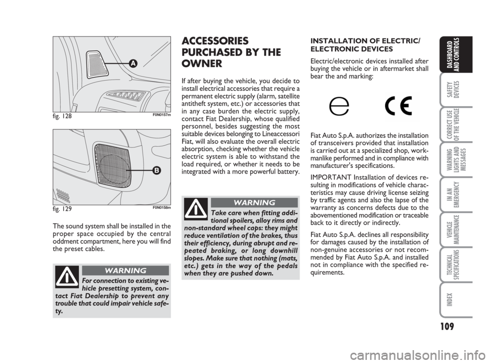
The sound system shall be installed in the
proper space occupied by the central
oddment compartment, here you will find
the preset cables.
fig. 128F0N0157m
ACCESSORIES
PURCHASED BY THE
OWNER
If after buying the vehicle, you decide to
install electrical accessories that require a
permanent electric supply (alarm, satellite
antitheft system, etc.) or accessories that
in any case burden the electric supply,
contact Fiat Dealership, whose qualified
personnel, besides suggesting the most
suitable devices belonging to Lineaccessori
Fiat, will also evaluate the overall electric
absorption, checking whether the vehicle
electric system is able to withstand the
load required, or whether it needs to be
integrated with a more powerful battery.
For connection to existing ve-
hicle presetting system, con-
tact Fiat Dealership to prevent any
trouble that could impair vehicle safe-
ty.
WARNING
fig. 129F0N0158mTake care when fitting addi-
tional spoilers, alloy rims and
non-standard wheel caps: they might
reduce ventilation of the brakes, thus
their efficiency, during abrupt and re-
peated braking, or long downhill
slopes. Make sure that nothing (mats,
etc.) gets in the way of the pedals
when they are pushed down.
WARNING
INSTALLATION OF ELECTRIC/
ELECTRONIC DEVICES
Electric/electronic devices installed after
buying the vehicle or in aftermarket shall
bear the and marking:
Fiat Auto S.p.A. authorizes the installation
of transceivers provided that installation
is carried out at a specialized shop, work-
manlike performed and in compliance with
manufacturer's specifications.
IMPORTANT Installation of devices re-
sulting in modifications of vehicle charac-
teristics may cause driving license seizing
by traffic agents and also the lapse of the
warranty as concerns defects due to the
abovementioned modification or traceable
back to it directly or indirectly.
Fiat Auto S.p.A. declines all responsibility
for damages caused by the installation of
non-genuine accessories or not recom-
mended by Fiat Auto S.p.A. and installed
not in compliance with the specified re-
quirements.
Page 111 of 282

110
SAFETY
DEVICES
CORRECT USE
OF THE
VEHICLE
WARNING
LIGHTS AND
MESSAGES
IN AN
EMERGENCY
VEHICLE
MAINTENANCE
TECHNICAL
SPECIFICATIONS
INDEX
DASHBOARD
AND CONTROLS
AT THE FILLING
STATION
OPERATION AT LOW
TEMPERATURES
If the outside temperature is very low, the
diesel thickens due to the formation of
paraffin and could cause the malfunction-
ing of the fuel system.
In order to avoid these problems, differ-
ent types of diesel are distributed ac-
cording to the season: summer type, win-
ter type and arctic type (cold, mountain
areas). If refuelling with diesel fuel not suit-
able for the current temperature, mix
diesel fuel with TUTELA DIESEL ART ad-
ditive in the proportions stated on the can,
putting first the antifreeze in the tank and
then the diesel fuel.
If driving or parking the vehicle for a long
period in cold areas/mountains, refuel with
the diesel fuel available at local filling sta-
tions.
In this situation you are also recom-
mended to have in the tank an amount of
fuel 50% higher than usable capacity. RADIO TRANSMITTERS AND
CELLULAR TELEPHONES
Radio transceiver equipment (e.g.: e-tacs
mobile phones, HAM radio systems and
the like) shall not be used inside the ve-
hicle unless a separate aerial is mounted
on the roof.
IMPORTANT The use of similar devices
inside the passenger compartment (with-
out separated aerial) produces radio-fre-
quency electromagnetic fields which, am-
plified by the resonance effects inside the
passenger compartment, may cause elec-
trical systems equipping the vehicle to mal-
function. This could compromise safety in
addition to constituting a potential hazard
for the passengers.
In addition, transmission and reception of
these devices may be affected by the
shielding effect of the vehicle body.
As concerns EC-approved mobile phones
(GSM, GPRS, UMTS), strictly comply with
the instructions for use provided by the
mobile phone’s manufacturer.
fig. 129a - Left drive versionF0N0245m
fig. 129b - Right side versionF0N0246m
PREARRANGEMENT OF
TELEPASS ASSEMBLY ON
REFLECTING WINDSHIELD
(where provided)
If the vehicle has a reflecting windshield
you have to install the telepass in the area
shown on fig. 129a-129b, in order to as-
sure proper operation.
Page 112 of 282

111
SAFETY
DEVICES
CORRECT USE
OF THE
VEHICLE
WARNING
LIGHTS AND
MESSAGES
IN AN
EMERGENCY
VEHICLE
MAINTENANCE
TECHNICAL
SPECIFICATIONS
INDEX
DASHBOARD
AND CONTROLS
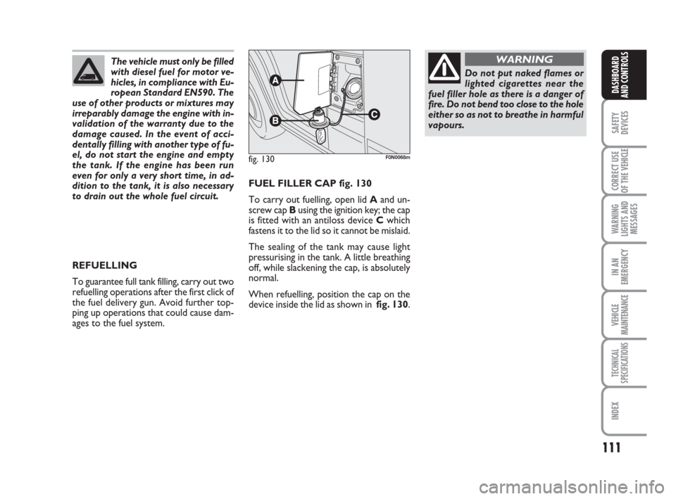
FUEL FILLER CAP fig. 130
To carry out fuelling, open lid Aand un-
screw cap Busing the ignition key; the cap
is fitted with an antiloss device Cwhich
fastens it to the lid so it cannot be mislaid.
The sealing of the tank may cause light
pressurising in the tank. A little breathing
off, while slackening the cap, is absolutely
normal.
When refuelling, position the cap on the
device inside the lid as shown in fig. 130.
fig. 130F0N0068m
Do not put naked flames or
lighted cigarettes near the
fuel filler hole as there is a danger of
fire. Do not bend too close to the hole
either so as not to breathe in harmful
vapours.
WARNINGThe vehicle must only be filled
with diesel fuel for motor ve-
hicles, in compliance with Eu-
ropean Standard EN590. The
use of other products or mixtures may
irreparably damage the engine with in-
validation of the warranty due to the
damage caused. In the event of acci-
dentally filling with another type of fu-
el, do not start the engine and empty
the tank. If the engine has been run
even for only a very short time, in ad-
dition to the tank, it is also necessary
to drain out the whole fuel circuit.
REFUELLING
To guarantee full tank filling, carry out two
refuelling operations after the first click of
the fuel delivery gun. Avoid further top-
ping up operations that could cause dam-
ages to the fuel system.