2009 FIAT DUCATO side lights
[x] Cancel search: side lightsPage 176 of 282

175
WARNING
LIGHTS AND
MESSAGES
VEHICLE
MAINTENANCE
TECHNICAL
SPECIFICATIONS
INDEX
DASHBOARD
AND CONTROLS
SAFETY
DEVICES
CORRECT USE
OF THE
VEHICLE
IN AN
EMERGENCY
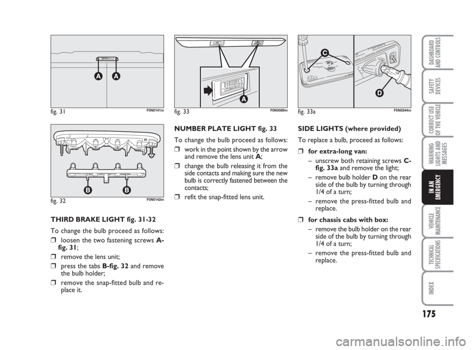
THIRD BRAKE LIGHT fig. 31-32
To change the bulb proceed as follows:
❒loosen the two fastening screws A-
fig. 31;
❒remove the lens unit;
❒press the tabs B-fig. 32and remove
the bulb holder;
❒remove the snap-fitted bulb and re-
place it.NUMBER PLATE LIGHT fig. 33
To change the bulb proceed as follows:
❒work in the point shown by the arrow
and remove the lens unit A;
❒change the bulb releasing it from the
side contacts and making sure the new
bulb is correctly fastened between the
contacts;
❒refit the snap-fitted lens unit.fig. 32F0N0142m
fig. 33F0N0089mfig. 31F0N0141mfig. 33aF0N0244m
SIDE LIGHTS (where provided)
To replace a bulb, proceed as follows:
❒for extra-long van:
– unscrew both retaining screws C-
fig. 33aand remove the light;
– remove bulb holder Don the rear
side of the bulb by turning through
1/4 of a turn;
– remove the press-fitted bulb and
replace.
❒for chassis cabs with box:
– remove the bulb holder on the rear
side of the bulb by turning through
1/4 of a turn;
– remove the press-fitted bulb and
replace.
Page 177 of 282

176
WARNING
LIGHTS AND
MESSAGES
VEHICLE
MAINTENANCE
TECHNICAL
SPECIFICATIONS
IINDEX
DASHBOARD
AND CONTROLS
SAFETY
DEVICES
CORRECT USE
OF THE
VEHICLE
IN AN
EMERGENCY
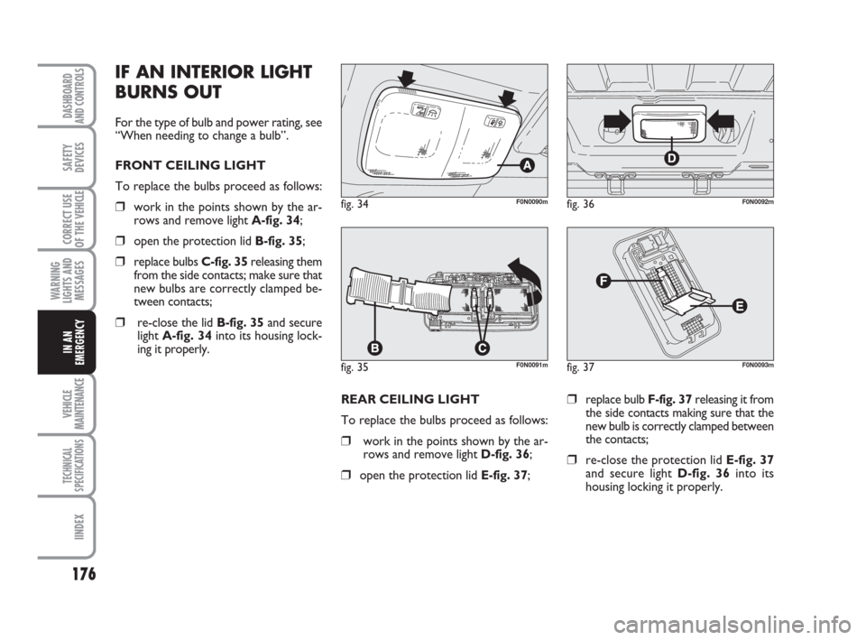
REAR CEILING LIGHT
To replace the bulbs proceed as follows:
❒work in the points shown by the ar-
rows and remove light D-fig. 36;
❒open the protection lid E-fig. 37;
❒replace bulb F-fig. 37releasing it from
the side contacts making sure that the
new bulb is correctly clamped between
the contacts;
❒re-close the protection lid E-fig. 37
and secure light D-fig. 36into its
housing locking it properly.
fig. 34F0N0090m
fig. 35F0N0091m
fig. 36F0N0092m
fig. 37F0N0093m
IF AN INTERIOR LIGHT
BURNS OUT
For the type of bulb and power rating, see
“When needing to change a bulb”.
FRONT CEILING LIGHT
To replace the bulbs proceed as follows:
❒work in the points shown by the ar-
rows and remove light A-fig. 34;
❒open the protection lid B-fig. 35;
❒replace bulbs C-fig. 35releasing them
from the side contacts; make sure that
new bulbs are correctly clamped be-
tween contacts;
❒re-close the lid B-fig. 35and secure
light A-fig. 34into its housing lock-
ing it properly.
Page 185 of 282

184
WARNING
LIGHTS AND
MESSAGES
VEHICLE
MAINTENANCE
TECHNICAL
SPECIFICATIONS
IINDEX
DASHBOARD
AND CONTROLS
SAFETY
DEVICES
CORRECT USE
OF THE
VEHICLE
IN AN
EMERGENCY
USERSFUSE AMPERE
Fuel pump F21 15
E.i. system (primary services) F22 20
ABS solenoid valves F23 30
Automatic transmission 8 (+key) F24 15
Front fog lightsF30 15
Right central post optional fuse box
USERSFUSE AMPERE
AbsentF54 –
Heated seatsF55 15
Rear passenger’s current outlet F56 15
Additional heater under seat F57 10
SidelightsF58 10
Self-levelling suspensions (+battery) F59 7.5
AbsentF60 –
AbsentF61 –
AbsentF62 –
Passenger’s additional heater control F63 10
AbsentF64 –
Passenger’s additional heater fan F65 30
Page 199 of 282

198
WARNING
LIGHTS AND
MESSAGES
TECHNICAL
SPECIFICATIONS
INDEX
DASHBOARD
AND CONTROLS
SAFETY
DEVICES
CORRECT USE
OF THE VEHICLE
IN AN
EMERGENCY
VEICHLE
MAINTENANCE
ENGINE OIL CONSUMPTION
Max engine oil consumption is usually 400
grams every 1,000 km.
When the vehicle is new, the engine needs
to run in, therefore the engine oil con-
sumption can only be considered stabilised
after the first 5,000 - 6,000 km.
IMPORTANT The oil consumption de-
pends on driving style and the conditions
under which the vehicle is used. ENGINE OIL fig. 4-5-6
Check the oil level a few minutes (about
5) after the engine has stopped, with the
vehicle parked on level ground.
The oil level shall be included between the
MINand MAXmarks on the dipstick B.
The gap between the MINand MAX
marks corresponds to about one litre of
oil.
If the oil level is near or even below the
MINmark, add oil through the filler neck
A, until reaching the MAXmark.
Oil level shall never exceed the MAX
mark.
fig. 4 - 100 Multijet versionsF0N0101mfig. 5 - 120 - 130 Multijet versions
fig. 6 - 160 Multijet versionsF0N0102m
F0N0211m
When the engine is hot, take
care when working inside the
engine compartment to avoid burns.
Remember that when the engine is
hot, fan may cut in: danger of injury.
Scarves, ties and other loose cloth-
ing might be pulled by moving parts.
WARNING
Do not add oil with specifica-
tions other than that already
in the engine.
Used engine oil and filter con-
tain harmful substances for
the environment. Contact Fi-
at Dealership to have the oil
and filter changed, as they are
equipped to dispose of the waste oil
and filters respecting the nature and
the law.
IMPORTANT After adding or changing
the oil, let the engine turn over for a few
seconds and wait a few minutes after turn-
ing it off before you check the level.
Page 202 of 282

201
WARNING
LIGHTS AND
MESSAGES
TECHNICAL
SPECIFICATIONS
INDEX
DASHBOARD
AND CONTROLS
SAFETY
DEVICES
CORRECT USE
OF THE VEHICLE
IN AN
EMERGENCY
VEHICLE
MAINTENANCE
Brake fluid is poisonous and
highly corrosive. In the event
of accidental contact, wash the parts
involved immediately with neutral
soap and water, then rinse thor-
oughly. Call the doctor immediately
if the fluid is swallowed.
WARNING
The symbol πon the con-
tainer indicates synthetic
brake fluid, distinguishing it from the
mineral kind. Using mineral fluids ir-
reversibly damages the special brak-
ing system rubber seals.
WARNING
POWER STEERING
FLUID fig. 10
Check whether the fluid level in the tank
is at max. level. This operation should be
carried out with the vehicle on level
ground, engine not running and cold.
Check whether the fluid level is at MAX
mark on the dipstick integral with the tank
cap (for cold check use the level shown
on the 20 °C side on the dipstick).If the fluid level in the reservoir is below
the specified level, top up with one of the
products specified in table “Fluids and lu-
bricants” in section “Technical Specifica-
tions”, proceed as follows:
❒Start the engine and wait until the flu-
id level in the reservoir has stabilized.
❒With the engine started, turn repeat-
edly the steering wheel fully right-
wards and leftwards.
❒Top up until reaching the MAXmark
then refit the cap.
fig. 10F0N0109m
Do not allow the power
steering fluid to touch the
hot parts of the engine: it is inflam-
mable.
WARNING
Do not press down the pow-
er steering with the engine
running for over 8 seconds,
noise and risk of damages will
result.
Power steering fluid con-
sumption is extremely low. If
the fluid level needs topping
up again after a short period
of time, have the system checked for
leakage at a Fiat Dealership.
AIR CLEANER
Air cleaner replacement shall be carried
out at Fiat Dealership.
AIR FILTER – DUSTY ROADS
(where necessary)
The air filter specific for dusty areas is
equipped with a visual blockage signalling
device A-fig. 11. It is therefore necessary
to periodically check the blockage sensor
indicator (Please refer to the “Pro-
grammed Maintenance Plan” shown in the
Chapter “Maintenance and care”)
Page 203 of 282

202
WARNING
LIGHTS AND
MESSAGES
TECHNICAL
SPECIFICATIONS
INDEX
DASHBOARD
AND CONTROLS
SAFETY
DEVICES
CORRECT USE
OF THE VEHICLE
IN AN
EMERGENCY
VEICHLE
MAINTENANCE
ATTENTION: Use a jet of air so as to
clean the air filter, do not use water or liq-
uid detergents.
Such filter is specific for the versions suit-
able for dusty areas; therefore it is advis-
able to seek help from the Fiat Assistance
Network for the substitution of the filter.
POLLEN FILTER
Pollen filter replacement shall be carried
out at Fiat Dealership.
BATTERY
The battery is of the “Limited mainte-
nance” type: under normal conditions of
use the electrolyte does not need topping
up with distilled water.
The battery is located inside the passen-
ger’s compartment in front of the pedal as-
sy. Remove the protection cover to find it.
Contact Fiat Dealership to have the bat-
tery checked/replaced.
CHECKING
THE CHARGE fig. 12
The battery charge may be checked
through the indicator A(where required)
set on the battery cover and acting ac-
cording to the colour the indicator shows.
The liquid in the battery is
poisonous and corrosive.
Avoid contact with eyes and skin. Do
not bring naked flames or possible
sources of sparks near the battery:
risk of fire and explosion.
WARNING
Running the battery with
low fluid level can damage
the battery beyond repair and could
also cause its explosion.
WARNING
Should the battery be not fitted with bat-
tery charge inspection device (optical elec-
trolyte indicator), inspection operations
shall be carried out by skilled personnel
only.
To check the battery charge, loosen the
two fastening screws and open the cov-
er. Then, close the cover accurately avoid-
ing pinching and short circuits.
Refer to the table below.
Upon reaching the calibration value, the
indicator is activated B-fig. 11aand it
switches to the red light position, even
when the engine is switched off. In order
to reset the signalling device, proceed with
the cleaning/substitution of the cartridge
as with normal equipment and reset the
indicator by pressing button C-fig. 11a.
fig. 11F0N0253m
fig. 11aF0N0254m
Page 206 of 282

205
WARNING
LIGHTS AND
MESSAGES
TECHNICAL
SPECIFICATIONS
INDEX
DASHBOARD
AND CONTROLS
SAFETY
DEVICES
CORRECT USE
OF THE VEHICLE
IN AN
EMERGENCY
VEHICLE
MAINTENANCE
WHEELS AND TYRES
Check the pressure of each tyre, includ-
ing the spare, every two weeks and before
long journeys. The pressure should be
checked with the tyre rested and cold.
It is normal for pressure to rise when you
are driving. For the correct tyre inflation
pressure, see “Wheels” in section “Tech-
nical specifications”.
Incorrect pressure causes abnormal tyre
wearfig. 13:
Anormal pressure: tread evenly worn.
Blow pressure: tread particularly worn
at the edges.
Chigh pressure: tread particularly worn
in the centre.
Tyres must be replaced when the tread
wears down to 1.6 mm. In any case, com-
ply with the laws in the country where the
vehicle is being driven.
fig. 13F0N0111m
IMPORTANT NOTES
❒As far as possible, avoid sharp brak-
ing and screech starts etc. Be careful
not to hit the kerb, potholes or oth-
er obstacles hard. Driving for long
stretches over bumpy roads can dam-
age the tyres;
❒periodically check that the tyres have
no cuts in the side wall, abnormal
swelling or irregular tyre wear. If any
of these occur, have the vehicle seen
to at a Fiat Dealership;
❒avoid overloading the vehicle when
travelling: this may cause serious dam-
age to the wheels and tyres;
❒if a tyre is punctured, stop immediately
and change it to avoid damage to the
tyre, the rim, suspensions and steer-
ing system;
❒tyres age even if they are not used
much. Cracks in the tread rubber are
a sign of ageing. In any case, if the
tyres have been on the vehicle for
over 6 years, they should be checked
by specialised personnel, to see if they
can still be used. Also remember to
check the spare wheel;
❒in the case of replacement, always fit
new tyres, avoiding those of dubious
origin;
❒if a tyre is changed, also change the in-
flation valve;
❒to allow even wear between the front
and rear tyres, it is advisable to change
them over every 10-15 thousand kilo-
metres, keeping them on the same
side of the vehicle so as to not reverse
the direction of rotation.
Remember that road holding
depends also on the correct
tyre inflating pressure.
WARNING
Page 209 of 282

208
WARNING
LIGHTS AND
MESSAGES
TECHNICAL
SPECIFICATIONS
INDEX
DASHBOARD
AND CONTROLS
SAFETY
DEVICES
CORRECT USE
OF THE VEHICLE
IN AN
EMERGENCY
VEICHLE
MAINTENANCE
BODY AND UNDERBODY
WARRANTY
Your vehicle is covered by warranty
against perforation due to rust of any orig-
inal element of the structure or body.
For the general terms of this warranty, re-
fer to Fiat Warranty Booklet.
ADVICE FOR PRESERVING THE
BODYWORK
Paint
Paintwork does not only serve an aesteth-
ic purpose, but also protects the under-
lying sheet metal.
In the case of deep scrapes or scores, you
are advised to have the necessary touching
up carried out immediately to avoid the for-
mation of rust. For touching up use only
original products (see “Bodywork paint
identification plate” in section “Technical
specifications”).
Normal paint maintenance consists in
washing at intervals depending on the con-
ditions and environment of use. For exam-
ple, in highly polluted areas, or if the roads
are sprayed with salt, it is wise to wash the
vehicle more frequently. These include:
❒Painting products and systems which
give the vehicle particular resistance
to corrosion and abrasion;
❒Use of galvanised (or pretreated)
steel sheets, with high resistance to
corrosion;
❒Spraying the underbody, engine com-
partment, wheelhouse internal parts
and other parts with highly protective
wax products;
❒Spraying of plastic parts, with a pro-
tective function, in the more exposed
points: underdoor, inner fender parts,
edges, etc;
❒Use of “open” boxed sections to pre-
vent condensation and pockets of
moisture from triggering rust inside.
BODYWORK
PROTECTION FROM
ATMOSPHERIC AGENTS
The main causes of corrosion are the fol-
lowing:
❒atmospheric pollution;
❒salty air and humidity (coastal areas,
or hot humid climates);
❒seasonal environment conditions.
Not to be underestimated is also the abra-
sive action of wind-borne atmospheric
dust and sand and mud and gravel raised
by other vehicles.
On your vehicle, Fiat implemented the
best manufacturing technologies to effec-
tively protect the bodywork against cor-
rosion.