Page 203 of 429
Reception Quality
Satellite reception may be interrupted due to one of the
following reasons:
•The vehicle is parked in an underground parking
structure or under a physical obstacle.
•Dense tree coverage may interrupt reception.
•Driving under wide bridges or along tall buildings can
cause intermittent reception.
•Placing objects over or too close to the antenna can
cause signal blockage.
VIDEO ENTERTAINMENT SYSTEM™ (SALES
CODE XRV) — IF EQUIPPED
The optional Video Entertainment System (VES)™ con-
sists of a DVD player and LCD (liquid crystal display)
screen, a battery-powered remote control, and two head-
sets. The system is located in the headliner behind thefront row seat. Refer to your VES™ User’s Manual for
detailed operating instructions.
REMOTE SOUND SYSTEM CONTROLS — IF
EQUIPPED
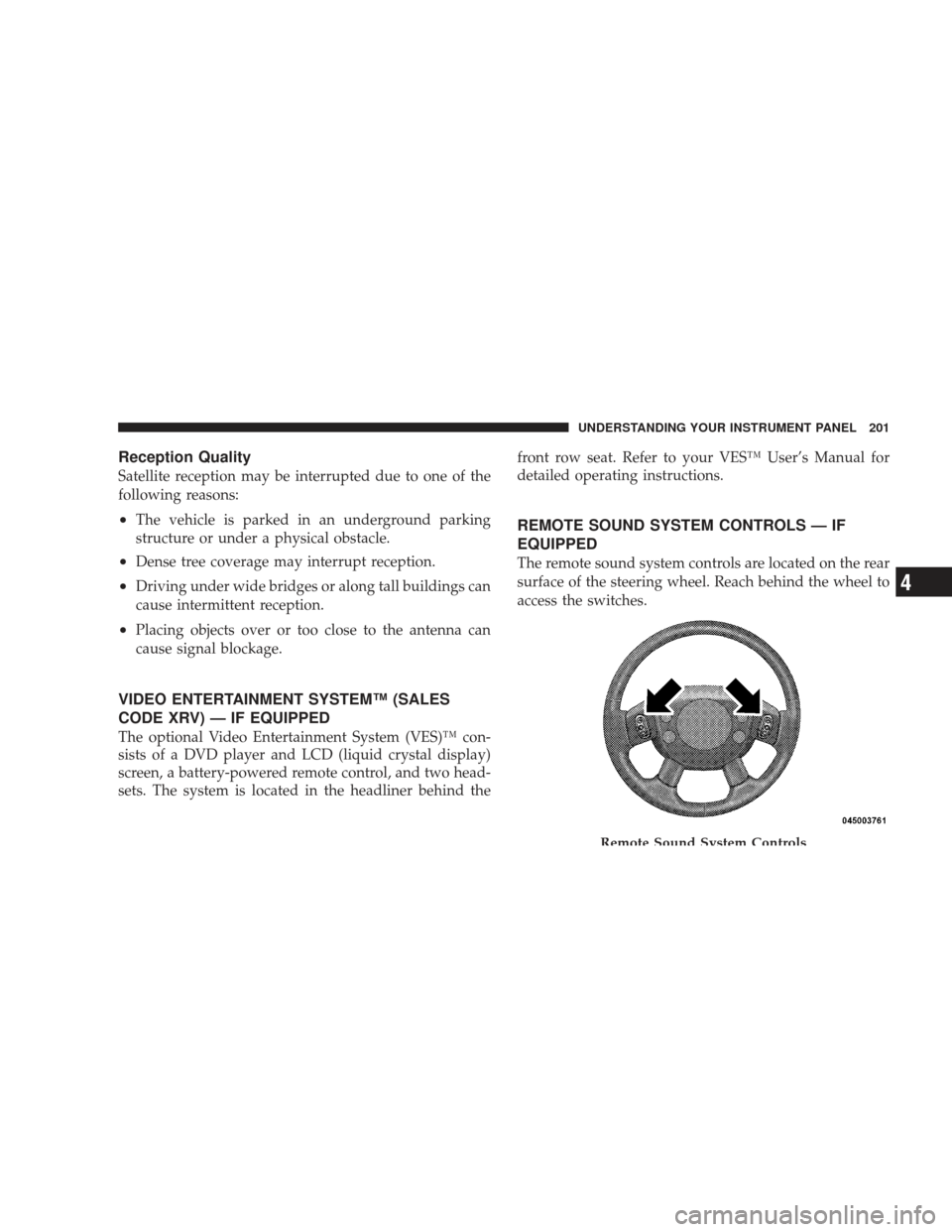
The remote sound system controls are located on the rear
surface of the steering wheel. Reach behind the wheel to
access the switches.
Remote Sound System Controls
UNDERSTANDING YOUR INSTRUMENT PANEL 201
4
Page 225 of 429
WARNING! (Continued)
•If the vehicle has a discharged battery, booster
cables may be used to obtain a start from a booster
battery or the battery in another vehicle. This type
of start can be dangerous if done improperly. Refer
to “Jump Starting” in Section 6.
If the engine has been flooded, it may start to run, but not
have enough power to continue running when the key is
released. If this occurs, continue cranking with the accel-
erator pedal pushed all the way to the floor. Release the
accelerator pedal and the key once the engine is running
smoothly.
If the engine shows no sign of starting after two 15-
second periods of cranking with the accelerator pedal
held to the floor, the “Normal Starting” procedure should
be repeated.
After Starting
The idle speed is automatically controlled and will de-
crease as the engine warms up.
ENGINE BLOCK HEATER — IF EQUIPPED
The engine block heater warms the engine, and permits
quicker starts in cold weather. Connect the cord to a
standard 110-115 Volt AC electrical outlet with a
grounded, three-wire extension cord.
The engine block heater cord is routed under the hood on
the driver side of the vehicle. It has a removable cap that
is located on the driver’s side of the Integrated Power
Module.
WARNING!
Remember to disconnect the cord before driving.
Damage to the 110-115 Volt electrical cord could cause
electrocution.
STARTING AND OPERATING 223
5
Page 251 of 429
LIMITED-SLIP DIFFERENTIAL – IF EQUIPPED
The limited-slip differential provides additional traction
on snow, ice, mud, sand and gravel, particularly when
there is a difference between the traction characteristics
of the surface under the right and left rear wheels. During
normal driving and cornering, the limited-slip unit per-
forms similarly to a conventional differential. On slip-
pery surfaces, however, the differential delivers more of
the driving effort to the rear wheel having the better
traction.
The limited-slip differential is especially helpful during
slippery driving conditions. With both rear wheels on a
slippery surface, a slight application of the accelerator
will supply maximum traction. When starting with only
one rear wheel on an excessively slippery surface, slight
momentary application of the parking brake may be
necessary to gain maximum traction.WARNING!
On vehicles equipped with a limited-slip differential
never run the engine with one rear wheel off the
ground since the vehicle may drive through the rear
wheel remaining on the ground. You could lose
control of the vehicle.
Care should be taken to avoid sudden accelerations when
both rear wheels are on a slippery surface. This could
cause both rear wheels to spin, and allow the vehicle to
slide sideways on the crowned surface of a road or in a
turn.
STARTING AND OPERATING 249
5
Page 288 of 429
WARNING!
•Never have any smoking materials lit in or near
the vehicle when the gas cap is removed or the
tank filled.
•Never add fuel to the vehicle when the engine is
running. This is in violation of most state and
federal fire regulations and will cause the MIL to
turn on.
NOTE: Tighten the gas cap 1/4 turn until you hear one
click. This is an indication that the cap is properly
tightened.
If the gas cap is not tightened properly, the Malfunction
Indicator Light will come on, Be sure the gas cap is
tightened every time the vehicle is refueled.
WARNING!
A fire may result if gasoline is pumped into a
portable container that is inside of a vehicle. You
could be burned. Always place gas containers on the
ground while filling.
Loose Fuel Filler Cap (Gas Cap) Message
If the vehicle’s diagnostic system determines that the fuel
filler cap in loose, improperly installed or damaged, a
GASCAP message will be displayed in the instrument
cluster. Tighten the gas cap until a “clicking” sound is
heard. This is an indication that the gas cap is properly
tightened. Press the odometer reset button to turn the
message off. If the problem persists, the message will
appear the next time the vehicle is started. This might
indicate a damaged cap. If the problem is detected twice
in a row, the system will turn on the MIL. Resolving the
problem will turn the MIL off.
286 STARTING AND OPERATING
Page 290 of 429
Tire Size
The tire size on the Label represents the actual tire size on
your vehicle. Replacement tires must be equal to the load
capacity of this tire size.
Rim Size
This is the rim size that is appropriate for the tire size
listed.
Inflation Pressure
This is the cold tire inflation pressure for your vehicle for
all loading conditions up to full GAWR.
Curb Weight
The curb weight of a vehicle is defined as the total weight
of the vehicle with all fluids, including vehicle fuel, at full
capacity conditions, and with no occupants or cargo
loaded into the vehicle. The front and rear curb weight
values are determined by weighing your vehicle on a
commercial scale before any occupants or cargo are
added.
Loading
The actual total weight and the weight of the front and
rear of your vehicle at the ground can best be determined
by weighing it when it is loaded and ready for operation.
The entire vehicle should first be weighed on a commer-
cial scale to insure that the GVWR has not been exceeded.
The weight on the front and rear of the vehicle should
then be determined separately to be sure that the load is
properly distributed over front and rear axle. Weighing
the vehicle may show that the GAWR of either the front
or rear axles has been exceeded but the total load is
within the specified GVWR. If so, weight must be shifted
from front to rear or rear to front as appropriate until the
specified weight limitations are met. Store the heavier
items down low and be sure that the weight is distributed
equally. Stow all loose items securely before driving.
288 STARTING AND OPERATING
Page 303 of 429
Dodge Body Builders Guide. See your authorized dealer,
installer or snowplow manufacturer for this information.
There are unique electrical systems that must be con-
nected to properly assure operator safety and prevent
overloading vehicle systems.
WARNING!
Attaching a snowplow to this vehicle could adversely
affect performance of the airbag system in an acci-
dent. Do not expect that the airbag will perform as
described earlier in this manual
CAUTION!
The “Lamp Out” indicator could illuminate if exte-
rior lamps are not properly installed.
Before Plowing
•
Check the hydraulic system for leaks and proper fluid
level.
•Check the mounting bolts and nuts for proper tight-
ness.
•Check the runners and cutting edge for excessive wear.
The cutting edge should be 1/4 to 1/2 in (6 cm to
1.2 cm) above ground in snow plowing position.
•Check that snowplow lighting is connected and func-
tioning properly.
STARTING AND OPERATING 301
5
Page 306 of 429
•Operate with transfer case in 4L when plowing small
or congested areas where speeds are not likely to
exceed 15 mph (24 km/h). At higher speeds operate in
4H.
•Vehicles with automatic transmissions should use 4L
range when plowing deep or heavy snow for extended
periods of time to avoid transmission overheating.
•Do not shift the transmission unless the engine has
returned to idle and wheels have stopped. Make a
practice of stepping on the brake pedal before shifting
the transmission.
RECREATIONAL TOWING (BEHIND
MOTORHOME, ETC.)
CAUTION!
Front or rear wheel lifts should not be used. Internal
damage to the transmission or transfer case will occur
if a front or rear wheel lift is used when recreational
towing.
Recreational Towing – 2-Wheel Drive Models
Recreational towing of 2-Wheel Drive models is not
allowed.Towing with the rear wheels on the ground can
result in severe transmission damage.
304 STARTING AND OPERATING
Page 320 of 429
WARNING! (Continued)
•If working on or near a roadway, be extremely
careful of motor traffic.
•To assure that spare tires, flat or inflated are
securely stowed, spares must be stowed with the
valve stem facing the ground.
•Turn on the Hazard Warning Flasher.1. If equipped, remove the spare wheel, jack, and tools
from storage.
2. Using the wheel wrench, loosen, but do not remove,
the wheel nuts by turning them counterclockwise one
turn while the wheel is still on the ground.
3. When changing the front wheel, assemble the jack
drive tube to the jack and connect the drive tube to the
extension tube. Place the jack under the axle as close to
the tire as possible with the drive tubes extending to the
front. Connect the jack tube extension and wheel wrench.
Jack Warning Label
318 WHAT TO DO IN EMERGENCIES