Page 146 of 429
ELECTRICAL POWER OUTLETS
The auxiliary electrical outlet can provide power for
in-cab accessories designed for use with the standard
“cigar lighter” plug. The outlet is located in the instru-
ment panel below and to the right of the climate control
panel. A cap is attached to the outlet base indicating
“Power Outlet” 12-Volt/20 A.
There is an additional power outlet inside the center
console of vehicles equipped with 40-20-40, or bucket
front seats. There is also a power outlet located on the
rear of the center console (if equipped with bucket seats).
The outlet(s) has/have a fused direct feed from the
battery so it/they receive power whether the ignition is
ON or OFF.
All accessories connected to this/these outlet(s) should
be removed or turned off when the vehicle is not in use
to protect the battery against discharge.NOTE:
If desired, all of the power outlets can be
converted by your authorized dealer to provide power
with the ignition switch in the ON position only.
WARNING!
To avoid serious injury or death:
•Do not use a three-prong adapter.
•Do not insert any objects into the receptacles.
•Do not touch with wet hands.
•Close the lid when not in use and while driving
the vehicle.
•If this outlet is mishandled, it may cause an
electric shock and failure.
144 UNDERSTANDING THE FEATURES OF YOUR VEHICLE
Page 147 of 429
CAUTION!
•Many accessories that can be plugged in draw
power from the vehicle’s battery, even when not in
use (i.e., cellular phones, etc.). Eventually, if
plugged in long enough, the vehicle’s battery will
discharge sufficiently to degrade battery life
and/or prevent engine starting.
•Accessories that draw higher power (i.e., coolers,
vacuum cleaners, lights, etc.), will discharge the
battery even more quickly. Only use these inter-
mittently and with greater caution.
•After the use of high power draw accessories, or
long periods of the vehicle not being started (with
accessories still plugged in), the vehicle must be
driven a sufficient length of time to allow the
generator to recharge the vehicle’s battery.
CIGAR LIGHTER AND ASH RECEIVER
The removable ash receiver is located in the instrument
panel cupholder tray.
The cigar lighter is located on the instrument panel,
above and to the left of the ash receiver.
As a child safety precaution, the lighter only operates
with the ignition switch ON. It heats when pushed in and
pops out automatically when ready for use.To preserve
the heating element, do not hold the lighter in the
heating position.
UNDERSTANDING THE FEATURES OF YOUR VEHICLE 145
3
Page 151 of 429
WARNING!
•This armrest is not a seat. Anyone seated on the
armrest could be seriously injured during vehicle
operation, or an accident. Only use the center
seating position when the armrest is fully upright.
•In an accident, the latch may open if the total
weight of the items stored exceeds about 10 lbs
(4.5 kg). These items could be thrown about en-
dangering occupants of the vehicle. Items stored
should not exceed a total of 10 lbs (4.5 kg).
CAUTION!
•Many accessories that can be plugged in draw
power from the vehicle’s battery, even when not in
use (i.e., cellular phones, etc.). Eventually, if
plugged in long enough, the vehicle’s battery will
discharge sufficiently to degrade battery life
and/or prevent engine starting.
•Accessories that draw higher power (i.e. coolers,
vacuum cleaners, lights, etc.), will degrade the
battery even more quickly. Only use these inter-
mittently and with greater caution.
•After the use of high power draw accessories, or
long periods of the vehicle not being started (with
accessories still plugged in), the vehicle must be
driven a sufficient length of time to allow the
generator to recharge the vehicle’s battery.
UNDERSTANDING THE FEATURES OF YOUR VEHICLE 149
3
Page 153 of 429
WARNING!
•This armrest is not a seat. Anyone seated on the
armrest could be seriously injured during vehicle
operation, or an accident. Only use the center
seating position when the armrest is fully upright.
•In an accident, the latch may open if the total
weight of the items stored exceeds about 10 lbs
(4.5 kg). These items could be thrown about en-
dangering occupants of the vehicle. Items stored
should not exceed a total of 10 lbs (4.5 kg).
CAUTION!
•Many accessories that can be plugged in draw
power from the vehicle’s battery, even when not in
use (i.e., cellular phones, etc.). Eventually, if
plugged in long enough, the vehicle’s battery will
discharge sufficiently to degrade battery life
and/or prevent engine starting.
•Accessories that draw higher power (i.e. coolers,
vacuum cleaners, lights, etc.), will degrade the
battery even more quickly. Only use these inter-
mittently and with greater caution.
•After the use of high power draw accessories, or
long periods of the vehicle not being started (with
accessories still plugged in), the vehicle must be
driven a sufficient length of time to allow the
generator to recharge the vehicle’s battery.
UNDERSTANDING THE FEATURES OF YOUR VEHICLE 151
3
Page 164 of 429

INSTRUMENT CLUSTER DESCRIPTION
1. Check GaugesThis light illuminates when the Voltmeter, Engine
Oil Pressure or Engine Coolant Temperature
gauges indicate a reading either too high or too low.
Examine the gauges carefully, and follow the instructions
contained below for each indicated problem.
NOTE: When the ignition switch is turned to OFF, the
Fuel Gauge, Voltmeter, Oil Pressure and Engine Coolant
Temperature gauges may not show accurate readings.
When the engine is not running, turn the ignition switch
to ON to obtain accurate readings.
2. Voltmeter When the engine is running, the gauge indicates
the electrical system voltage. The pointer should
stay within the normal range if the battery is charged. If the pointer moves to either extreme left or right and
remains there during normal driving, the electrical sys-
tem should be serviced.
NOTE:
•If the gauge pointer moves to either extreme of the
gauge, the “Check Gauges” indicator will illuminate
and a single chime will sound.
•The voltmeter may show a gauge fluctuation at vari-
ous engine temperatures. This cycling operation is
caused by the post-heat cycle of the intake manifold
heater system. The number of cycles and the length of
the cycling operation is controlled by the engine
control module. Post-heat operation can run for sev-
eral minutes, and then the electrical system and volt-
meter needle will stabilize.
3. Turn Signal Indicators Lights in instrument cluster flash when outside turn
signals are operating.
162 UNDERSTANDING YOUR INSTRUMENT PANEL
Page 203 of 429
Reception Quality
Satellite reception may be interrupted due to one of the
following reasons:
•The vehicle is parked in an underground parking
structure or under a physical obstacle.
•Dense tree coverage may interrupt reception.
•Driving under wide bridges or along tall buildings can
cause intermittent reception.
•Placing objects over or too close to the antenna can
cause signal blockage.
VIDEO ENTERTAINMENT SYSTEM™ (SALES
CODE XRV) — IF EQUIPPED
The optional Video Entertainment System (VES)™ con-
sists of a DVD player and LCD (liquid crystal display)
screen, a battery-powered remote control, and two head-
sets. The system is located in the headliner behind thefront row seat. Refer to your VES™ User’s Manual for
detailed operating instructions.
REMOTE SOUND SYSTEM CONTROLS — IF
EQUIPPED
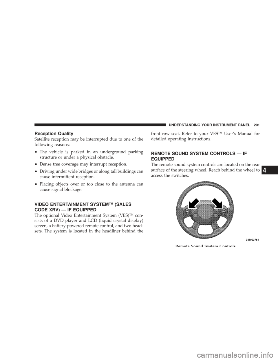
The remote sound system controls are located on the rear
surface of the steering wheel. Reach behind the wheel to
access the switches.
Remote Sound System Controls
UNDERSTANDING YOUR INSTRUMENT PANEL 201
4
Page 225 of 429
WARNING! (Continued)
•If the vehicle has a discharged battery, booster
cables may be used to obtain a start from a booster
battery or the battery in another vehicle. This type
of start can be dangerous if done improperly. Refer
to “Jump Starting” in Section 6.
If the engine has been flooded, it may start to run, but not
have enough power to continue running when the key is
released. If this occurs, continue cranking with the accel-
erator pedal pushed all the way to the floor. Release the
accelerator pedal and the key once the engine is running
smoothly.
If the engine shows no sign of starting after two 15-
second periods of cranking with the accelerator pedal
held to the floor, the “Normal Starting” procedure should
be repeated.
After Starting
The idle speed is automatically controlled and will de-
crease as the engine warms up.
ENGINE BLOCK HEATER — IF EQUIPPED
The engine block heater warms the engine, and permits
quicker starts in cold weather. Connect the cord to a
standard 110-115 Volt AC electrical outlet with a
grounded, three-wire extension cord.
The engine block heater cord is routed under the hood on
the driver side of the vehicle. It has a removable cap that
is located on the driver’s side of the Integrated Power
Module.
WARNING!
Remember to disconnect the cord before driving.
Damage to the 110-115 Volt electrical cord could cause
electrocution.
STARTING AND OPERATING 223
5
Page 305 of 429

Over the Road Operation With Snowplow
Attached
The blade restricts air flow to the radiator and causes the
engine to operate at higher than normal temperatures.
Therefore, when transporting the plow, angle the blade
completely and position it as low as road or surface
conditions permit. Do not exceed 40 mph (64 km/h). The
operator should always maintain a safe stopping distance
and allow adequate passing clearance.
Operating Tips
Under ideal snow plowing conditions, 20 mph (32 km/h)
should be maximum operating speed. The operator
should be familiar with the area and surface to be
cleaned. Reduce speed and use extreme caution when
plowing unfamiliar areas or under poor visibility.
NOTE:During snowplow usage on vehicles equipped
with an overhead console module, the outside tempera-
ture display will show higher temperatures than the outside ambient temperature. The higher displayed tem-
perature is due to blocked or reduced airflow to the
underhood ambient temperature sensor by the snow-
plow. This is common and outside temperature display
operation will return to normal when the snowplow is
removed.
General Maintenance
Snowplows should be maintained in accordance with the
plow manufacturer’s instructions.
Keep all snowplow electrical connections and battery
terminals clean and free of corrosion.
When plowing snow, to avoid transmission and drive-
train damage, the following precautions should be ob-
served.
STARTING AND OPERATING 303
5