2009 DODGE CALIBER SRT service indicator
[x] Cancel search: service indicatorPage 166 of 411

INSTRUMENT CLUSTER DESCRIPTIONS
1. Fuel Gauge
When the ignition switch is in the ON position, the
pointer will show the level of fuel remaining in the fuel
tank.
2. Fuel Door Indicator
This indicates that the Fuel Filler Door is
located on the left side of the vehicle.
3. Temperature Gauge
The temperature gauge shows engine coolant tem-
perature. Any reading below thered(260 °F /
126.6 °C) area of the gauge shows that the engine
cooling system is operating properly. The gauge pointer
may show a higher than normal temperature when
driving in hot weather, up mountain grades, or in heavy
stop-and-go traffic.If the pointer rises to theredmark (260 °F / 126.6 °C), the
instrument cluster will sound a chime. Pull over and stop
the vehicle. Idle the vehicle with the air conditioner
turned off until the pointer drops back into the normal
range. If the pointer remains on theredmark (260 °F /
126.6 °C), turn the engine off immediately and call for
service.
There are steps that you can take to slow down an
impending overheat condition. If your air conditioning is
on, turn it off. The air conditioning system adds heat to
the engine cooling system and turning off the A/C
removes this heat. You can also turn the Temperature
control to maximum heat, the Mode control to Floor and
the Fan control to High. This allows the heater core to act
as a supplement to the radiator and aids in removing heat
from the engine cooling system.
164 UNDERSTANDING YOUR INSTRUMENT PANEL
Page 169 of 411
If the light turns on while driving, safely pull over and
stop the vehicle. If the A/C system is on, turn it off. Also,
shift the transmission into NEUTRAL and idle the ve-
hicle. If the temperature reading does not return to
normal, turn the engine off immediately and call for
service. Refer to “If Your Engine Overheats” in Section 6
for more information.
12. Speedometer
Indicates vehicle speed.
13. Odometer/Trip Odometer
This display indicates the total distance the vehicle has
been driven. Also, the cluster will display, replacing the
odometer/trip odometer, vehicle warning messages such
as: door/gate ajar and gASCAP (loose gas cap) and
Change Oil message.
NOTE:
If the vehicle is equipped with the optional Elec-
tronic Vehicle Information Center (EVIC) in the instrument
cluster, all warnings including “door”, and “gATE” and OilChange Required will only be displayed in the EVIC display.
For additional information, refer to “Electronic Vehicle In-
formation Center — If Equipped” in Section 3.
Change Oil Message
Your vehicle is equipped with an engine oil change
indicator system. The “Change Oil” message will flash in
the instrument cluster odometer for approximately
12 seconds after a single chime has sounded to indicate
the next scheduled oil change interval. The engine oil
change indicator system is duty cycle based, which
means the engine oil change interval may fluctuate
dependent upon your personal driving style.
Unless reset, this message will continue to display each time
you turn the ignition switch to the ON/RUN position. To
turn off the message temporarily, press and release the Trip
Odometer button on the instrument cluster. To reset the oil
change indicator system (after performing the scheduled
maintenance) refer to the following procedure.
UNDERSTANDING YOUR INSTRUMENT PANEL 167
4
Page 170 of 411

1. Turn the ignition switch to the ON position.Do not
start the engine.
2. Fully depress the accelerator pedal slowly three
times within 10 seconds.
3. Turn the ignition switch to the OFF/LOCK position.
NOTE:If the indicator message illuminates when you
start the vehicle, the oil change indicator system did not
reset. If necessary repeat this procedure.
14. Cruise Indicator — If Equipped
This indicator shows that the Speed Control
System is ON.
15. Odometer/Trip Odometer Display Reset Button
Press this button to change the display from odometer to
either of the two trip odometer settings. Trip A or Trip B
will appear when in the trip odometer mode. Push in andhold the button for two seconds to reset the trip odometer
to 0 miles (0 km). The odometer must be in Trip Mode to
reset.
16. Electronic Throttle Control (ETC) Light
This light informs you of a problem with the
Electronic Throttle Control (ETC) system. If a
problem is detected, the light will come on
while the engine is running. Cycle the ignition
key when the vehicle has completely stopped and the
shift lever is placed in the PARK position. The light
should turn off. If the light remains lit with the engine
running your vehicle will usually be drivable, however,
see an authorized dealer for service as soon as possible. If
the light is flashing when the engine is running, imme-
diate service is required and you may experience reduced
performance, an elevated/rough idle or engine stall and
your vehicle may require towing. The light will come on
when the ignition is first turned ON and remain on
168 UNDERSTANDING YOUR INSTRUMENT PANEL
Page 172 of 411
The light will remain on until the cause is corrected.
NOTE:The light may flash momentarily during sharp
cornering maneuvers, which change fluid level condi-
tions. The vehicle should have service performed, and
the brake fluid level checked.
If brake failure is indicated, immediate repair is neces-
sary.
WARNING!
Driving a vehicle with the red brake light on is
dangerous. Part of the brake system may have failed.
It will take longer to stop the vehicle. You could have
an accident. Have the vehicle checked immediately.
Vehicles equipped with the Anti-Lock Brake System
(ABS), are also equipped with Electronic Brake Force
Distribution (EBD). In the event of an EBD failure, theBrake Warning Light will turn on along with the ABS
Light. Immediate repair to the ABS system is required.
Operation of the Brake Warning Light can be checked by
turning the ignition switch from the OFF position to the
ON position. The light should illuminate for approxi-
mately two seconds. The light should then turn off unless
the parking brake is applied or a brake fault is detected.
If the light does not illuminate, have the light inspected
by an authorized dealer.
The light also will turn on when the parking brake is
applied with the ignition switch in the ON position.
NOTE:This light shows only that the parking brake is
applied. It does not show the degree of brake application.
19. Turn Signal Indicators
The arrow will flash with the exterior turn signal
when the turn signal lever is operated.
170 UNDERSTANDING YOUR INSTRUMENT PANEL
Page 175 of 411

CAUTION!
The TPMS has been optimized for the original
equipment tires and wheels. TPMS pressures and
warning have been established for the tire size
equipped on your vehicle. Undesirable system opera-
tion or sensor damage may result when using re-
placement equipment that is not of the same size,
type, and/or style. Aftermarket wheels can cause
sensor damage. Do not use tire sealant from a can, or
balance beads if your vehicle is equipped with a
TPMS, as damage to the sensors may result.
23. Malfunction Indicator Light (MIL)
The Malfunction Indicator Light (MIL) is part of
an Onboard Diagnostic system called OBD II that
monitors emissions, engine, and automatic trans-
mission control systems. The MIL will illuminate when
the key is in the ON/RUN position before engine start. Ifthe bulb does not come on when turning the key from
OFF to ON/RUN, have the condition checked promptly.
Certain conditions such as a loose or missing gas cap,
poor fuel quality, etc. may illuminate the MIL after engine
start. The vehicle should be serviced if the MIL stays on
through several of your typical driving cycles. In most
situations the vehicle will drive normally and will not
require towing.
If the MIL flashes when the engine is running, serious
conditions may exist that could lead to immediate loss of
power or severe catalytic converter damage. The vehicle
should be serviced as soon as possible if this occurs.
24. Anti-Lock Brake (ABS) Light
This light monitors the Anti-Lock Brake System
(ABS). The light will turn on when the ignition
switch is turned to the ON position and may
stay on for as long as four seconds.
UNDERSTANDING YOUR INSTRUMENT PANEL 173
4
Page 176 of 411
If the ABS light remains on or turns on while driving, it
indicates that the Anti-Lock portion of the brake system
is not functioning and that service is required. However,
the conventional brake system will continue to operate
normally if the BRAKE warning light is not on.
If the ABS light is on, the brake system should be serviced
as soon as possible to restore the benefits of Anti-Lock
brakes. If the ABS light does not turn on when the
Ignition switch is turned to the ON position, have the
light inspected by an authorized dealer.
25. High Beam Indicator
This light shows that the headlights are on high
beam. Push the turn signal lever away from the
steering wheel to switch the headlights from high or low
beam.26. Electronic Vehicle Information Center (EVIC)
Button — If Equipped
Pushing this button will switch between the different
EVIC functions.
27. Electronic Vehicle Information Center (EVIC)
Display — If Equipped
Refer to Electronic vehicle Information Center (EVIC) in
this section for more information.
ELECTRONIC VEHICLE INFORMATION CENTER
(EVIC)
The Electronic Vehicle Information Center (EVIC) fea-
tures a driver-interactive display that is located in the
instrument cluster.
174 UNDERSTANDING YOUR INSTRUMENT PANEL
Page 286 of 411
Many states have laws requiring tire replacement at this
point.
Life of Tire
The service life of a tire is dependent upon varying
factors, including, but not limited to:
•Driving style
•Tire pressure
•Distance driven
WARNING!
The tires and the spare tire should be replaced after
six years, regardless of the remaining tread. Failure to
follow this warning can result in sudden tire failure.
You could lose control and have an accident resulting
in serious injury or death.Keep dismounted tires in a cool, dry place with as little
exposure to light as possible. Protect tires from contact
with oil, grease and gasoline.
Replacement Tires
The tires on your new vehicle provide a balance of many
characteristics. They should be inspected regularly for
wear and correct cold tire inflation pressure. The manu-
facturer strongly recommends that you use tires equiva-
lent to the originals in size, quality and performance
when replacement is needed. Please see “Tread Wear
Indicators” and “Tire and Loading Information” placard
for the size designation of your tire. The service descrip-
tion and load identification will be found on the original-
equipment tire. Failure to use equivalent replacement
tires may adversely affect the safety, handling, and ride of
your vehicle. We recommend that you contact your
original-equipment manufacturer, or an authorized tire
dealer, with any questions you may have on tire specifi-
cations or capability.
284 STARTING AND OPERATING
Page 308 of 411
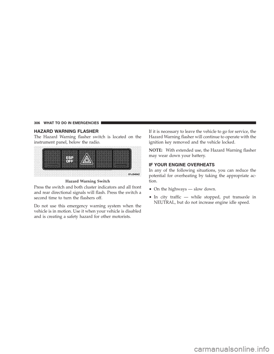
HAZARD WARNING FLASHER
The Hazard Warning flasher switch is located on the
instrument panel, below the radio.
Press the switch and both cluster indicators and all front
and rear directional signals will flash. Press the switch a
second time to turn the flashers off.
Do not use this emergency warning system when the
vehicle is in motion. Use it when your vehicle is disabled
and is creating a safety hazard for other motorists.If it is necessary to leave the vehicle to go for service, the
Hazard Warning flasher will continue to operate with the
ignition key removed and the vehicle locked.
NOTE:With extended use, the Hazard Warning flasher
may wear down your battery.
IF YOUR ENGINE OVERHEATS
In any of the following situations, you can reduce the
potential for overheating by taking the appropriate ac-
tion.
•On the highways — slow down.
•In city traffic — while stopped, put transaxle in
NEUTRAL, but do not increase engine idle speed.
Hazard Warning Switch
306 WHAT TO DO IN EMERGENCIES