Page 199 of 543

Rear Park Assist Sensors
The four Rear Park Assist sensors, located in the rear
fascia, monitor the area behind the vehicle that is within
the sensors’ field of view. The monitored area seems oval
in shape. The sensors can detect obstacles from approxi-
mately 11.8 in (30 cm) up to 78.7 in (200 cm) from the rear
fascia in the horizontal direction, depending on the
location and orientation of the obstacle and the type of
obstacle.
Rear Park Assist Warning Display
The Rear Park Assist Warning Display, located in the
headliner near the liftgate glass, provides both visible
and audible warnings to indicate the distance between
the rear fascia and the detected obstacle.When the ignition switch is turned to the RUN/ON
position, the warning display will turn on all of its LEDs
for about one second. Each side of the warning display
has six yellow and two red LED lights, one set to warn of
obstacles behind the left rear of the vehicle and the other
set to warn of obstacles behind the right rear of the
vehicle. The vehicle is close to the obstacle when the red
LED is illuminated.Rear Park Assist LED Lights
3
UNDERSTANDING THE FEATURES OF YOUR VEHICLE 197
Page 220 of 543
WARNING! (Continued)
•Close the lid when not in use and while driving
the vehicle.
•If this outlet is mishandled, it may cause an
electric shock and failure.
CAUTION!
•Many accessories that can be plugged in draw
power from the vehicle’s battery, even when not in
use (i.e., cellular phones, etc.). Eventually, if
plugged in long enough, the vehicle’s battery will
discharge sufficiently to degrade battery life
and/or prevent the engine from starting.(Continued)
CAUTION! (Continued)
•Accessories that draw higher power (i.e., coolers,
vacuum cleaners, lights, etc.), will degrade the
battery even more quickly. Only use these inter-
mittently and with greater caution.
•After the use of high power draw accessories, or
long periods of the vehicle not being started (with
accessories still plugged in), the vehicle must be
driven a sufficient length of time to allow the
alternator to recharge the vehicle’s battery.
•Power outlets are designed for accessory plugs
only. Do not hang any type of accessory or acces-
sory bracket from the plug. Improper use of the
power outlet can cause damage.
218 UNDERSTANDING THE FEATURES OF YOUR VEHICLE
Page 231 of 543
3. Remove the console.
To Reinstall The Basic Floor Console
1. Position the console at a slight angle (front slightly
higher than the rear).
2. Slide the console rearward into the floor bracket/
hook.
3. Align the console until the front anchor cup plug hole
is centered on the winch hole.
4. Reinstall the clip first and then while pushing down-
ward on the console with slight pressure, reinstall the
cover plug.
5. Pull up on the console to be sure it is firmly latched.
WARNING!
In an accident, serious injury could result if the
removable floor console is not properly installed.
Always be sure the removable floor console is fully
latched.
Premium Console — If Equipped
The three-compartment console with sliding storage bin,
sliding upper tray with storage and large console storage
bin offers multiple configurations.
•Four cupholders with dishwasher safe liners for clean-
ing. The cupholders can accept plastic bottles, large
cups or mugs with handles.
•Top tray storage
•Upper storage bin can hold nine regular or 18 thin CDs
or other items
3
UNDERSTANDING THE FEATURES OF YOUR VEHICLE 229
Page 235 of 543
3. Pull rearward to disengage from floor and remove
console.
To reinstall the console:
1. Position the console at a slight angle (rear slightly
higher than the front).
2. Slide the console forward into the floor bracket.
3. Rotate the rear of the console down until it is resting
on the floor bracket.
4. Push down on the rear of the console until it is seated
in the rear floor bracket.
5. Pull up on the console to be sure it is firmly latched.WARNING!
In an accident, serious injury could result if the
removable floor console is not properly installed.
Always be sure the removable floor console is fully
latched.
REAR WINDOW FEATURES
Rear Window Defroster
The rear window defroster button is located on the
climate control (Mode) knob. Press this button to
turn on the rear window defroster and the heated outside
mirrors (if equipped). An indicator in the button will
illuminate when the rear window defroster is on. The
rear window defroster automatically turns off after ap-
proximately 10 minutes. For an additional five minutes of
operation, press the button a second time.
3
UNDERSTANDING THE FEATURES OF YOUR VEHICLE 233
Page 249 of 543

illuminated. This sequence will continue upon subse-
quent vehicle start-ups as long as the malfunction exists.
When the malfunction indicator is illuminated, the sys-
tem may not be able to detect or signal low tire pressure
as intended. TPMS malfunctions may occur for a variety
of reasons, including the installation of replacement or
alternate tires or wheels on the vehicle that prevent the
TPMS from functioning properly. Always check the
TPMS malfunction telltale after replacing one or more
tires or wheels on your vehicle, to ensure that the
replacement or alternate tires and wheels allow the TPMS
to continue to function properly.CAUTION!
The TPMS has been optimized for the original
equipment tires and wheels. TPMS pressures and
warning have been established for the tire size
equipped on your vehicle. Undesirable system opera-
tion or sensor damage may result when using re-
placement equipment that is not of the same size,
type, and/or style. Aftermarket wheels can cause
sensor damage. Do not use tire sealant from a can, or
balance beads if your vehicle is equipped with a
TPMS, as damage to the sensors may result.
6. Oil Pressure Warning Light This light indicates low engine oil pressure. The
light should turn on momentarily when the engine
is started. If the light turns on while driving, stop the
4
UNDERSTANDING YOUR INSTRUMENT PANEL 247
Page 250 of 543
vehicle and shut off the engine as soon as possible. A
chime will sound for four minutes when this light turns
on.
Do not operate the vehicle until the cause is corrected.
This light does not indicate how much oil is in the engine.
The engine oil level must be checked under the hood.
7. Engine Temperature Warning LightThis light warns of an overheated engine condi-
tion. As temperatures rise and the gauge ap-
proaches H, this indicator will illuminate and a
single chime will sound after reaching a set threshold.
Further overheating will cause the temperature gauge to
pass H, the indicator will continuously flash and a
continuous chime will occur until the engine is allowed
to cool.
If the light turns on while driving, safely pull over and
stop the vehicle. If the A/C system is on, turn it off. Also, shift the transmission into NEUTRAL and idle the ve-
hicle. If the temperature reading does not return to
normal, turn the engine off immediately and call for
service. Refer to “If Your Engine Overheats” in Section 6
for more information.
8. Speedometer
Indicates vehicle speed.
9. Turn Signal Indicators
The arrow will flash with the exterior turn signal
when the turn signal lever is operated.
If the vehicle electronics sense that the vehicle has
traveled about 1 mile (1.6 km) with the turn signals on, a
continuous chime will sound to alert you to turn the
signals off. If either indicator flashes at a rapid rate, check
for a defective outside light bulb.
248 UNDERSTANDING YOUR INSTRUMENT PANEL
Page 251 of 543
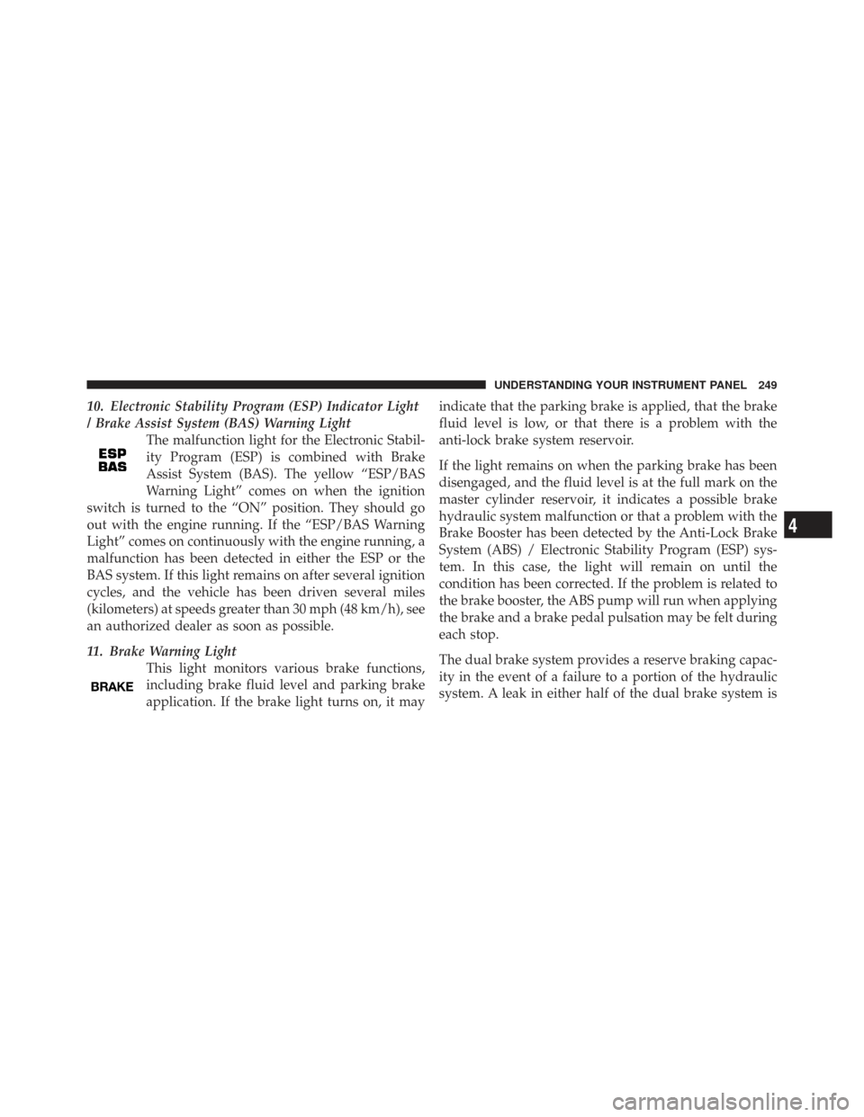
10. Electronic Stability Program (ESP) Indicator Light
/ Brake Assist System (BAS) Warning LightThe malfunction light for the Electronic Stabil-
ity Program (ESP) is combined with Brake
Assist System (BAS). The yellow “ESP/BAS
Warning Light” comes on when the ignition
switch is turned to the “ON” position. They should go
out with the engine running. If the “ESP/BAS Warning
Light” comes on continuously with the engine running, a
malfunction has been detected in either the ESP or the
BAS system. If this light remains on after several ignition
cycles, and the vehicle has been driven several miles
(kilometers) at speeds greater than 30 mph (48 km/h), see
an authorized dealer as soon as possible.
11. Brake Warning Light This light monitors various brake functions,
including brake fluid level and parking brake
application. If the brake light turns on, it may indicate that the parking brake is applied, that the brake
fluid level is low, or that there is a problem with the
anti-lock brake system reservoir.
If the light remains on when the parking brake has been
disengaged, and the fluid level is at the full mark on the
master cylinder reservoir, it indicates a possible brake
hydraulic system malfunction or that a problem with the
Brake Booster has been detected by the Anti-Lock Brake
System (ABS) / Electronic Stability Program (ESP) sys-
tem. In this case, the light will remain on until the
condition has been corrected. If the problem is related to
the brake booster, the ABS pump will run when applying
the brake and a brake pedal pulsation may be felt during
each stop.
The dual brake system provides a reserve braking capac-
ity in the event of a failure to a portion of the hydraulic
system. A leak in either half of the dual brake system is
4
UNDERSTANDING YOUR INSTRUMENT PANEL 249
Page 252 of 543
indicated by the Brake Warning Light, which will turn on
when the brake fluid level in the master cylinder has
dropped below a specified level.
The light will remain on until the cause is corrected.
NOTE:The light may flash momentarily during sharp
cornering maneuvers, which change fluid level condi-
tions. The vehicle should have service performed, and
the brake fluid level checked.
If brake failure is indicated, immediate repair is neces-
sary.
WARNING!
Driving a vehicle with the red brake light on is
dangerous. Part of the brake system may have failed.
It will take longer to stop the vehicle. You could have
an accident. Have the vehicle checked immediately. Vehicles equipped with the Anti-Lock Brake System
(ABS), are also equipped with Electronic Brake Force
Distribution (EBD). In the event of an EBD failure, the
Brake Warning Light will turn on along with the ABS
Light. Immediate repair to the ABS system is required.
Operation of the Brake Warning Light can be checked by
turning the ignition switch from the OFF position to the
ON position. The light should illuminate for approxi-
mately two seconds. The light should then turn off unless
the parking brake is applied or a brake fault is detected.
If the light does not illuminate, have the light inspected
by an authorized dealer.
The light also will turn on when the parking brake is
applied with the ignition switch in the ON position.
NOTE:
This light shows only that the parking brake is
applied. It does not show the degree of brake application.
250 UNDERSTANDING YOUR INSTRUMENT PANEL