2009 CHRYSLER TOWN AND COUNTRY engine
[x] Cancel search: enginePage 185 of 543
The headlight delay time is programmable on vehicles
equipped with an EVIC. Refer to “Delay Turning Head-
lights Off,” under “Personal Settings (Customer-
Programmable Features)” under “Electronic Vehicle In-
formation Center (EVIC)” in Section 4.
If the headlights are turned off before the ignition, they
will turn off in the normal manner.
NOTE:The headlights must be turned off within 45 sec-
onds of turning the ignition OFF to activate this feature.
Lights-On Reminder
If the headlights or the parking lights are left on, or if the
dimmer control is in the extreme top position after the
ignition switch is turned OFF, a chime will sound when
the driver’s door is opened.
Daytime Running Lights (Canada/Fleet Vehicles
Only)
The headlights on your vehicle will illuminate when the
engine is started and the transmission is in any gear
except PARK. This provides a constant lights on condi-
tion until the ignition is turned OFF. The lights illuminate
at less than 50% of normal intensity. If the parking brake
is applied, the Daytime Running Lights (DRL) will turn
off. Also, if a turn signal is activated, the DRL lamp on the
same side of the vehicle will turn off for the duration of
the turn signal activation. Once the turn signal is no
longer active, the DRL lamp will illuminate.
Front Fog Lights — If Equipped
To activate the front fog lights, turn on the parking
lights or the low beam headlights and push in the
headlight switch control knob. Pressing the head-
light switch control knob in a second time will turn the
front fog lights off.
3
UNDERSTANDING THE FEATURES OF YOUR VEHICLE 183
Page 219 of 543
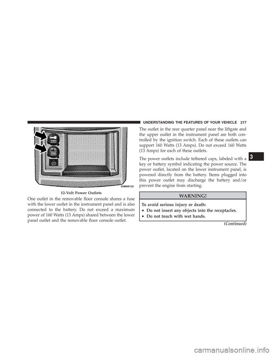
One outlet in the removable floor console shares a fuse
with the lower outlet in the instrument panel and is also
connected to the battery. Do not exceed a maximum
power of 160 Watts (13 Amps) shared between the lower
panel outlet and the removable floor console outlet.The outlet in the rear quarter panel near the liftgate and
the upper outlet in the instrument panel are both con-
trolled by the ignition switch. Each of these outlets can
support 160 Watts (13 Amps). Do not exceed 160 Watts
(13 Amps) for each of these outlets.
The power outlets include tethered caps, labeled with a
key or battery symbol indicating the power source. The
power outlet, located on the lower instrument panel, is
powered directly from the battery. Items plugged into
this power outlet may discharge the battery and/or
prevent the engine from starting.WARNING!
To avoid serious injury or death:
•Do not insert any objects into the receptacles.
•Do not touch with wet hands.
(Continued)
12-Volt Power Outlets
3
UNDERSTANDING THE FEATURES OF YOUR VEHICLE 217
Page 220 of 543
WARNING! (Continued)
•Close the lid when not in use and while driving
the vehicle.
•If this outlet is mishandled, it may cause an
electric shock and failure.
CAUTION!
•Many accessories that can be plugged in draw
power from the vehicle’s battery, even when not in
use (i.e., cellular phones, etc.). Eventually, if
plugged in long enough, the vehicle’s battery will
discharge sufficiently to degrade battery life
and/or prevent the engine from starting.(Continued)
CAUTION! (Continued)
•Accessories that draw higher power (i.e., coolers,
vacuum cleaners, lights, etc.), will degrade the
battery even more quickly. Only use these inter-
mittently and with greater caution.
•After the use of high power draw accessories, or
long periods of the vehicle not being started (with
accessories still plugged in), the vehicle must be
driven a sufficient length of time to allow the
alternator to recharge the vehicle’s battery.
•Power outlets are designed for accessory plugs
only. Do not hang any type of accessory or acces-
sory bracket from the plug. Improper use of the
power outlet can cause damage.
218 UNDERSTANDING THE FEATURES OF YOUR VEHICLE
Page 236 of 543
NOTE:
•You can turn off the heated mirror feature at anytime
by pressing the rear window defroster switch a second
time.
•To prevent excessive battery drain, use the rear win-
dow defroster only when the engine is operating.
CAUTION!
Failure to follow these cautions can cause damage to
the heating elements:
•Use care when washing the inside of the rear
window. Do not use abrasive window cleaners on
the interior surface of the window. Use a soft cloth
and a mild washing solution, wiping parallel to
the heating elements. Labels can be peeled off
after soaking with warm water.(Continued)
CAUTION! (Continued)
•Do not use scrapers, sharp instruments, or abra-
sive window cleaners on the interior surface of the
window.
•Keep all objects a safe distance from the window.
LOAD-LEVELING SYSTEM
The automatic load-leveling system will provide a level
riding vehicle under most passenger and cargo loading
conditions.
A hydraulic pump contained within the shock absorbers
raises the rear of the vehicle to the correct height. It takes
approximately 1 mile (1.6 km) of driving for the leveling
to complete depending on road surface conditions.
If the leveled vehicle is not moved for approximately
15 hours, the leveling system will bleed itself down. The
vehicle must be driven to reset the system.
234 UNDERSTANDING THE FEATURES OF YOUR VEHICLE
Page 247 of 543
INSTRUMENT CLUSTER DESCRIPTIONS
1. Fuel Gauge
The pointer shows the level of fuel in the fuel tank when
the ignition switch is in the ON position.
2. Low Fuel LightWhen the fuel level reaches approximately 2.0 gal
(7.8 L) this light will turn on, and remain on until
fuel is added.
3. Electronic Throttle Control (ETC) Light This light informs you of a problem with the
Electronic Throttle Control (ETC) system. The
light will come on when the ignition is first
turned ON and remain on briefly as a bulb
check. If the light does not come on during starting, have
the system checked by an authorized dealer.
If a problem is detected, the light will come on while the
engine is running. Cycle the ignition key when the vehicle has completely stopped and the shift lever is
placed in the PARK position, the light should turn off.
If the light remains lit with the engine running, your
vehicle will usually be drivable; however, see an autho-
rized dealer for service as soon as possible. If the light is
flashing when the engine is running, immediate service is
required and you may experience reduced performance,
an elevated/rough idle or engine stall and your vehicle
may require towing.
4. Charging System Light
This light shows the status of the electrical charg-
ing system. The light should come on when the
ignition switch is first turned ON and remain on briefly
as a bulb check. If the light stays on or comes on while
driving, turn off some of the vehicle’s non-essential
electrical devices or increase engine speed (if at idle). If
the charging system light remains on, it means that the
4
UNDERSTANDING YOUR INSTRUMENT PANEL 245
Page 249 of 543

illuminated. This sequence will continue upon subse-
quent vehicle start-ups as long as the malfunction exists.
When the malfunction indicator is illuminated, the sys-
tem may not be able to detect or signal low tire pressure
as intended. TPMS malfunctions may occur for a variety
of reasons, including the installation of replacement or
alternate tires or wheels on the vehicle that prevent the
TPMS from functioning properly. Always check the
TPMS malfunction telltale after replacing one or more
tires or wheels on your vehicle, to ensure that the
replacement or alternate tires and wheels allow the TPMS
to continue to function properly.CAUTION!
The TPMS has been optimized for the original
equipment tires and wheels. TPMS pressures and
warning have been established for the tire size
equipped on your vehicle. Undesirable system opera-
tion or sensor damage may result when using re-
placement equipment that is not of the same size,
type, and/or style. Aftermarket wheels can cause
sensor damage. Do not use tire sealant from a can, or
balance beads if your vehicle is equipped with a
TPMS, as damage to the sensors may result.
6. Oil Pressure Warning Light This light indicates low engine oil pressure. The
light should turn on momentarily when the engine
is started. If the light turns on while driving, stop the
4
UNDERSTANDING YOUR INSTRUMENT PANEL 247
Page 250 of 543
vehicle and shut off the engine as soon as possible. A
chime will sound for four minutes when this light turns
on.
Do not operate the vehicle until the cause is corrected.
This light does not indicate how much oil is in the engine.
The engine oil level must be checked under the hood.
7. Engine Temperature Warning LightThis light warns of an overheated engine condi-
tion. As temperatures rise and the gauge ap-
proaches H, this indicator will illuminate and a
single chime will sound after reaching a set threshold.
Further overheating will cause the temperature gauge to
pass H, the indicator will continuously flash and a
continuous chime will occur until the engine is allowed
to cool.
If the light turns on while driving, safely pull over and
stop the vehicle. If the A/C system is on, turn it off. Also, shift the transmission into NEUTRAL and idle the ve-
hicle. If the temperature reading does not return to
normal, turn the engine off immediately and call for
service. Refer to “If Your Engine Overheats” in Section 6
for more information.
8. Speedometer
Indicates vehicle speed.
9. Turn Signal Indicators
The arrow will flash with the exterior turn signal
when the turn signal lever is operated.
If the vehicle electronics sense that the vehicle has
traveled about 1 mile (1.6 km) with the turn signals on, a
continuous chime will sound to alert you to turn the
signals off. If either indicator flashes at a rapid rate, check
for a defective outside light bulb.
248 UNDERSTANDING YOUR INSTRUMENT PANEL
Page 251 of 543
10. Electronic Stability Program (ESP) Indicator Light
/ Brake Assist System (BAS) Warning LightThe malfunction light for the Electronic Stabil-
ity Program (ESP) is combined with Brake
Assist System (BAS). The yellow “ESP/BAS
Warning Light” comes on when the ignition
switch is turned to the “ON” position. They should go
out with the engine running. If the “ESP/BAS Warning
Light” comes on continuously with the engine running, a
malfunction has been detected in either the ESP or the
BAS system. If this light remains on after several ignition
cycles, and the vehicle has been driven several miles
(kilometers) at speeds greater than 30 mph (48 km/h), see
an authorized dealer as soon as possible.
11. Brake Warning Light This light monitors various brake functions,
including brake fluid level and parking brake
application. If the brake light turns on, it may indicate that the parking brake is applied, that the brake
fluid level is low, or that there is a problem with the
anti-lock brake system reservoir.
If the light remains on when the parking brake has been
disengaged, and the fluid level is at the full mark on the
master cylinder reservoir, it indicates a possible brake
hydraulic system malfunction or that a problem with the
Brake Booster has been detected by the Anti-Lock Brake
System (ABS) / Electronic Stability Program (ESP) sys-
tem. In this case, the light will remain on until the
condition has been corrected. If the problem is related to
the brake booster, the ABS pump will run when applying
the brake and a brake pedal pulsation may be felt during
each stop.
The dual brake system provides a reserve braking capac-
ity in the event of a failure to a portion of the hydraulic
system. A leak in either half of the dual brake system is
4
UNDERSTANDING YOUR INSTRUMENT PANEL 249