Page 311 of 543
REMOTE SOUND SYSTEM CONTROLS — IF
EQUIPPED
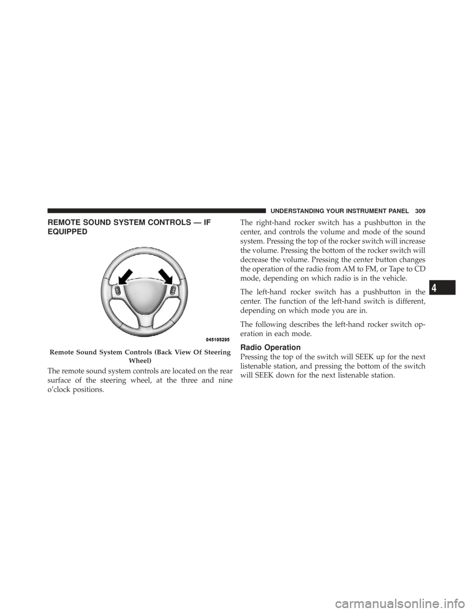
The remote sound system controls are located on the rear
surface of the steering wheel, at the three and nine
o’clock positions.The right-hand rocker switch has a pushbutton in the
center, and controls the volume and mode of the sound
system. Pressing the top of the rocker switch will increase
the volume. Pressing the bottom of the rocker switch will
decrease the volume. Pressing the center button changes
the operation of the radio from AM to FM, or Tape to CD
mode, depending on which radio is in the vehicle.
The left-hand rocker switch has a pushbutton in the
center. The function of the left-hand switch is different,
depending on which mode you are in.
The following describes the left-hand rocker switch op-
eration in each mode.
Radio Operation
Pressing the top of the switch will SEEK up for the next
listenable station, and pressing the bottom of the switch
will SEEK down for the next listenable station.Remote Sound System Controls (Back View Of Steering
Wheel)
4
UNDERSTANDING YOUR INSTRUMENT PANEL 309
Page 314 of 543
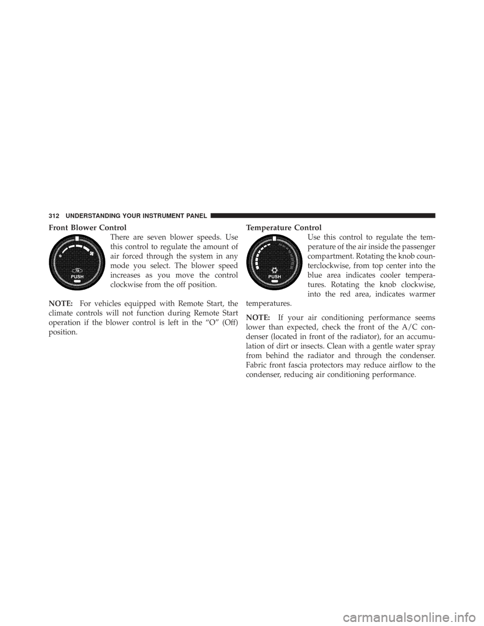
Front Blower Control
There are seven blower speeds. Use
this control to regulate the amount of
air forced through the system in any
mode you select. The blower speed
increases as you move the control
clockwise from the off position.
NOTE: For vehicles equipped with Remote Start, the
climate controls will not function during Remote Start
operation if the blower control is left in the “O” (Off)
position.
Temperature Control
Use this control to regulate the tem-
perature of the air inside the passenger
compartment. Rotating the knob coun-
terclockwise, from top center into the
blue area indicates cooler tempera-
tures. Rotating the knob clockwise,
into the red area, indicates warmer
temperatures.
NOTE: If your air conditioning performance seems
lower than expected, check the front of the A/C con-
denser (located in front of the radiator), for an accumu-
lation of dirt or insects. Clean with a gentle water spray
from behind the radiator and through the condenser.
Fabric front fascia protectors may reduce airflow to the
condenser, reducing air conditioning performance.
312 UNDERSTANDING YOUR INSTRUMENT PANEL
Page 320 of 543
Only when the front control for the rear blower is in the
RRposition do the second row seat occupants have
control of the rear blower speed.
The rear blower control, located in the rear overhead
console, has an off position and a range of blower speeds.
This allows the second row seat occupants to control the
volume of air circulated in the rear of the vehicle.
CAUTION!
Interior air enters the Rear Manual Climate Control
system through an intake grille, located in the pas-
senger side trim panel behind the third row seats.
The heater outlets are located in the passenger side
trim panel, just behind the sliding door. Do not block
or place objects directly in front of the inlet grille or
heater outlets. The electrical system could overload,
causing damage to the blower motor.
Rear Temperature Control
When the blower knob on the front climate control unit is
set to any position other than the rear temperature
settings will be controlled by the rear temperature control
knob on the front climate control unit. The rear mode
selection RR,allows the settings to be controlled by the
rear mode control knob.
To change the temperature in the rear of the vehicle,
rotate the temperature control knob counterclockwise for
cold air, and clockwise for heated air.
When rear controls are locked by the front system, the
lock symbol on the temperature knob is illuminated, and
the rear overhead adjustments are inoperable.
The rear airflow modes will mirror the front unit opera-
tion. Rear PANEL mode is automatically selected when
the front control is in the PANEL mode. When the front
unit is in BI-LEVEL mode, airflow will be emitted from
both the upper and lower rear outlets. When the front
318 UNDERSTANDING YOUR INSTRUMENT PANEL
Page 328 of 543
1. Press the REAR LOCK button on the front lower ATC
panel. This turns off the REAR LOCK icon in the rear
temperature knob.
2. Rotate the Rear Blower, Rear Temperature and the
Rear Mode Control knobs to suit your comfort needs.
3. ATC is selected by adjusting the rear blower knob
counterclockwise to AUTO.
Once the desired temperature is displayed, the ATC
System will automatically achieve and maintain that
comfort level. When the system is set up for your comfort
level, it is not necessary to change the settings. You will
experience the greatest efficiency by simply allowing the
system to function automatically.NOTE:
•It is not necessary to move the temperature settings for
cold or hot vehicles. The system automatically adjusts
the temperature, mode and fan speed to provide
comfort as quickly as possible.
•The temperature can be displayed in English or Metric
units by selecting the “Display Units of Measure in”
customer-programmable feature. Refer to the “Elec-
tronic Vehicle Information Center (EVIC) — Customer-
Programmable Features” in this Section.
Rear Blower Control
The rear blower control knob can be manually set to off,
or any fixed blower speed, by rotating the knob from low
to high. This allows the rear seat occupants to control the
volume of air circulated in the rear of the vehicle.
326 UNDERSTANDING YOUR INSTRUMENT PANEL
Page 329 of 543
CAUTION!
Interior air enters the Rear Automatic Temperature
Control System through an intake grille, located in
the passenger side trim panel behind the third row
seats. The heater outlets are located in the passenger
side trim panel, just behind the sliding door. Do not
block or place objects directly in front of the inlet
grille or heater outlets. The electrical system could
overload causing damage to the blower motor.
Rear Temperature Control
To change the temperature in the rear of the vehicle,
rotate the temperature knob counterclockwise to lower
the temperature, and clockwise to increase the tempera-
ture. The REAR temperature settings are displayed in the
front upper ATC panel.When rear controls are locked by the front system, the
LOCK symbol on the temperature knob is illuminated
and any rear overhead adjustments are ignored.
Rear Mode Control
Auto Mode
The rear system automatically maintains the correct
mode and comfort level desired by the rear seat occu-
pants.
Headliner Mode
Air comes from the outlets in the headliner. Each of
these outlets can be individually adjusted to direct
the flow of air. Moving the air vanes of the outlets to one
side will shut off the airflow.
Bi-Level Mode Air comes from both the headliner outlets and the
floor outlets.
4
UNDERSTANDING YOUR INSTRUMENT PANEL 327
Page 479 of 543
FUSES/TIPM
Cavity Cartridge
Fuse Mini-
Fuse Description
M10 — 15 Amp BlueIgnition Off Draw
— Vehicle Enter-
tainment System
(IOD-VES), Satellite
Digital Audio Re-
ceiver (SDARS),
DVD, Hands-Free
Module (HFM),
Universal Garage
Door Opener
(UGDO), Vanity
Lamp (VANITY
LP), Streaming
Video Module
M11 — 10 Amp Red(Ignition Off Draw)
IOD-HVAC/ATCFUSES/TIPM
Cavity Cartridge
Fuse Mini-
Fuse Description
M12 — 30 Amp GreenAmplifier (AMP)/
Radio
M13 — 20 Amp YellowIgnition Off
Draw— Cabin
Compartment Node
(IOD-CCN), SIREN,
Clock Module
(CLK MOD), Multi-
Function Control
Switch (MULTI-
FCTN SW)/ITM
M14 — 20 Amp YellowSpare Fuse
7
MAINTAINING YOUR VEHICLE 477
Page 487 of 543
3. Push the new bulb into the socket and reinstall the
socket by twisting until locked into the headlamp
housing.
Front Side Marker Lamp
1. Raise the hood to access the rear of the headlamp
housing.
NOTE:Access is somewhat limited. You may have to
remove the inner fender well or remove the headlamp
housing for bulb replacement.
2. Twist the socket and remove from the headlamp
housing, then pull the bulb out.
3. Push the new bulb into the socket and reinstall the
socket by twisting until locked into the headlamp
housing.
Fog Lamp
NOTE: Access to the fog lamp bulb is from the rear of
the fascia. On the left rear side of the fascia, remove the
push pin and lower the hinged access door on the air
dam.
1. From behind the bumper fascia, or the access panel on
the air dam, twist the bulb counterclockwise, and remove
bulb.
CAUTION!
Do not touch the new bulb with your fingers. Oil
contamination will severely shorten bulb life. If the
bulb comes in contact with an oily surface, clean the
bulb with rubbing alcohol.
2. Disconnect wire harness from the bulb.
7
MAINTAINING YOUR VEHICLE 485
Page 488 of 543
3. Reconnect the wiring harness to the new bulb and
reinstall the bulb by twisting clockwise.
Rear Tail, Stop, Turn Signal, Side Marker and
Backup Lamp
1. Raise the liftgate.
2. Remove the tail lamp assembly by removing the two
screws from the inboard side. Use a fiber stick or similar
tool to gently pry the light on the outboard side to
disengage the two ball studs.NOTE:
•If a screwdriver is used, make sure a soft material is
placed between the vehicle body and tool so not to
scratch the paint.
•The PRY location is best closest to the studs while
dislodging them separately.
Tail Lamp Housing Fastener Removal
486 MAINTAINING YOUR VEHICLE