Page 313 of 543
oversized, or have protection encoding. Try a known
good disc before considering disc player service.
RADIO OPERATION AND CELLULAR PHONES
Under certain conditions, the cellular phone being on in
your vehicle can cause erratic or noisy performance from
your radio. This condition may be lessened or eliminated
by relocating the cellular phone antenna. This condition
is not harmful to the radio. If your radio performance
does not satisfactorily “clear” by the repositioning of the
antenna, it is recommended that the radio volume be
turned down or off during cellular phone operation.
CLIMATE CONTROLS
The Climate Control System allows you to regulate the
temperature, amount, and direction of air circulating
throughout the vehicle. The controls are located on the
instrument panel, below the radio.
Manual Heating and Air Conditioning System
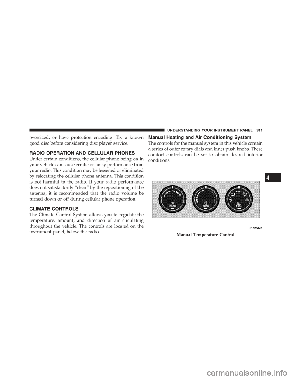
The controls for the manual system in this vehicle contain
a series of outer rotary dials and inner push knobs. These
comfort controls can be set to obtain desired interior
conditions.
Manual Temperature Control
4
UNDERSTANDING YOUR INSTRUMENT PANEL 311
Page 353 of 543
You may experience the following when the brake system
goes into anti-lock:
•The ABS motor running (it may continue to run for a
short time after the stop)
•A clicking sound of solenoid valves
•Brake pedal pulsations
•A slight drop or fall away of the brake pedal at the end
of the stop
WARNING!
•The Anti-Lock Brake System contains sophisti-
cated electronic equipment that may be suscep-
tible to interference caused by improperly in-
stalled, or high output radio transmitting
equipment. This interference can cause possible
loss of anti-lock braking capability. Installation of
such equipment should be performed by qualified
professionals.
•Pumping of the anti-lock brakes will diminish
their effectiveness and may lead to an accident.
Pumping makes the stopping distance longer. Just
press firmly on your brake pedal when you need
to slow down or stop.(Continued)
5
STARTING AND OPERATING 351
Page 381 of 543
The Basic TPMS consists of the following components:
•Receiver Module
•Four Tire Pressure Monitoring Sensors
•TPMS Telltale Warning Light
Tire Pressure Monitoring Low Tire Pressure
Warnings
The “TPMS Telltale Warning Light” will illu-
minate in the instrument cluster, and an au-
dible chime will be activated when one or more
of the four active road tire pressures are low.
Should this occur, you should stop as soon as possible,
check the inflation pressure of each tire on your vehicle,
and inflate each tire to the vehicle’s recommended cold
tire pressure value (located on the placard on the
driver’s-side B-Pillar). The system will automatically
update and the “TPMS Warning Lamp” will extinguish
once the updated tire pressures have been received. NOTE:
The vehicle may need to be driven for up to
20 minutes above 15 mph (25 km/h) to receive this
information.
The “TPMS Warning Lamp” will flash on and off for
75 seconds, and remain on solid when a system fault is
detected. The system fault will also sound a chime. If the
ignition key is cycled, this sequence will repeat, provid-
ing the system fault still exists. The “TPMS Warning
Lamp” will turn off when the fault condition no longer
exists. A system fault can occur with any of the following
scenarios:
1. Jamming due to electronic devices or driving next to
facilities emitting the same radio frequencies as the TPMS
sensors.
2. Installing some form of aftermarket window tinting
that affects radio wave signals.
5
STARTING AND OPERATING 379
Page 385 of 543
will not be present, and a pressure value will be dis-
played instead of dashes. A system fault can occur by any
of the following scenarios:
1. Jamming due to electronic devices or driving next to
facilities emitting the same radio frequencies as the TPMS
sensors.
2. Installing some form of aftermarket window tinting
that affects radio wave signals.
3. Accumulation of excessive snow and/or ice around
the wheels or wheel housings.
4. Using tire chains on the vehicle.
5. Using wheels/tires not equipped with TPMS sensors.
Vehicles with Compact Spare
1. The compact spare tire (if equipped) does not have a
TPMS. Therefore, the TPMS will not monitor the pressure
in the compact spare tire.2. If you install the compact spare tire in place of a road
tire that has a pressure below the low-pressure warning
limit, upon the next ignition key cycle, the “TPMS Telltale
Warning Light” will remain on, a chime will sound, and
the EVIC will still display a flashing pressure value in the
graphic display.
3. After driving the vehicle for up to 20 minutes above
15 mph (25 km/h), the “TPMS Telltale Warning Light”
will flash on and off for 75 seconds and then remain on
solid. In addition, the EVIC will display a CHECK TPM
SYSTEM message for three seconds and then display
dashes (- -) in place of the pressure value.
4. For each subsequent ignition key cycle, a chime will
sound, the “TPMS Telltale Warning Light” will flash on
and off for 75 seconds and then remain on solid, and the
EVIC will display a CHECK TPM SYSTEM message for
three seconds and then display dashes (- -) in place of the
pressure value.
5
STARTING AND OPERATING 383
Page 418 of 543
HAZARD WARNING FLASHER
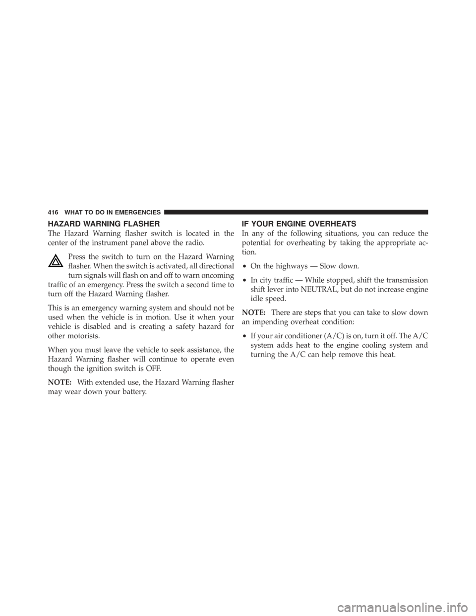
The Hazard Warning flasher switch is located in the
center of the instrument panel above the radio.Press the switch to turn on the Hazard Warning
flasher. When the switch is activated, all directional
turn signals will flash on and off to warn oncoming
traffic of an emergency. Press the switch a second time to
turn off the Hazard Warning flasher.
This is an emergency warning system and should not be
used when the vehicle is in motion. Use it when your
vehicle is disabled and is creating a safety hazard for
other motorists.
When you must leave the vehicle to seek assistance, the
Hazard Warning flasher will continue to operate even
though the ignition switch is OFF.
NOTE: With extended use, the Hazard Warning flasher
may wear down your battery.
IF YOUR ENGINE OVERHEATS
In any of the following situations, you can reduce the
potential for overheating by taking the appropriate ac-
tion.
•On the highways — Slow down.
•In city traffic — While stopped, shift the transmission
shift lever into NEUTRAL, but do not increase engine
idle speed.
NOTE: There are steps that you can take to slow down
an impending overheat condition:
•If your air conditioner (A/C) is on, turn it off. The A/C
system adds heat to the engine cooling system and
turning the A/C can help remove this heat.
416 WHAT TO DO IN EMERGENCIES
Page 433 of 543
WARNING! (Continued)
•Take special care to avoid the radiator cooling fan
whenever the hood is raised. The cooling fan is
electrically operated and can start anytime the
ignition switch is ON. You can be hurt by the fan.
•During cold weather when temperatures are be-
low the freezing point, electrolyte in a discharged
battery may freeze. Do not attempt jump-starting
because the battery could rupture or explode. The
battery temperature must be brought up above the
freezing point before attempting a jump-start.
When jump-starting, proceed as follows:
1. Wear eye protection and remove any metal jewelry,
such as watch bands or bracelets, that might make an
inadvertent electrical contact.
2. When a boost is provided by a battery in another
vehicle, park that vehicle within booster cable reach and do not let the vehicles touch. Set the parking brake, place
the automatic transmission shift lever into PARK and
turn the ignition switch to the OFF position for both
vehicles.
3. Turn off the heater, radio and all unnecessary electrical
loads.
4. Connect one end of a jumper cable to the positive
terminal of the discharged battery. Connect the other end
of the same cable to the positive terminal of the booster
battery.
WARNING!
Do not permit vehicles to touch each other, as this
could establish a ground connection and personal
injury could result.
6
WHAT TO DO IN EMERGENCIES 431
Page 474 of 543
Cleaning Headlights
Your vehicle has plastic headlights that are lightweight
and less susceptible to stone breakage than glass head-
lights.
Plastic is not as scratch resistant as glass and therefore
different lens cleaning procedures must be followed.
To minimize the possibility of scratching the lenses and
reducing light output, avoid wiping with a dry cloth. To
remove road dirt, wash with a mild soap solution fol-
lowed by rinsing.
Do not use abrasive cleaning components, solvents, steel
wool or other aggressive material to clean the lenses.
Glass Surfaces
All glass surfaces should be cleaned on a regular basis
with MOPAR�Glass Cleaner or any commercial
household-type glass cleaner. Never use an abrasive type cleaner. Use caution when cleaning the inside rear win-
dow equipped with electric defrosters or the right rear
quarter window equipped with the radio antenna. Do
not use scrapers or other sharp instruments that may
scratch the elements.
When cleaning the rearview mirror, spray cleaner on the
towel or rag that you are using. Do not spray cleaner
directly on the mirror.
Cleaning Plastic Instrument Cluster Lenses
The lenses in front of the instruments in this vehicle are
molded in clear plastic. When cleaning the lenses, care
must be taken to avoid scratching the plastic.
1. Clean with a wet soft rag. A mild soap solution may be
used, but do not use high alcohol content or abrasive
cleaners. If soap is used, wipe clean with a clean damp
rag.
2. Dry with a soft tissue.
472 MAINTAINING YOUR VEHICLE
Page 479 of 543
FUSES/TIPM
Cavity Cartridge
Fuse Mini-
Fuse Description
M10 — 15 Amp BlueIgnition Off Draw
— Vehicle Enter-
tainment System
(IOD-VES), Satellite
Digital Audio Re-
ceiver (SDARS),
DVD, Hands-Free
Module (HFM),
Universal Garage
Door Opener
(UGDO), Vanity
Lamp (VANITY
LP), Streaming
Video Module
M11 — 10 Amp Red(Ignition Off Draw)
IOD-HVAC/ATCFUSES/TIPM
Cavity Cartridge
Fuse Mini-
Fuse Description
M12 — 30 Amp GreenAmplifier (AMP)/
Radio
M13 — 20 Amp YellowIgnition Off
Draw— Cabin
Compartment Node
(IOD-CCN), SIREN,
Clock Module
(CLK MOD), Multi-
Function Control
Switch (MULTI-
FCTN SW)/ITM
M14 — 20 Amp YellowSpare Fuse
7
MAINTAINING YOUR VEHICLE 477