Page 131 of 410
If either light remains on and does not flash, or there is a
very fast flash rate, check for a defective outside light
bulb. If an indicator fails to light when the lever is
moved, it would suggest that the fuse or indicator bulb is
defective.
High Beam/Low Beam Select Switch
Push the multifunction lever away from the steering
wheel to switch the headlights to high beam. Pull the
lever toward the steering wheel to switch the headlights
back to low beam.
Turn Signal Control
High Beam, Low Beam, and Passing Lights
3
UNDERSTANDING THE FEATURES OF YOUR VEHICLE 129
Page 132 of 410
Flash-to-Pass
You can signal another vehicle with your headlights by
lightly pulling the multifunction lever toward the steer-
ing wheel. This will turn on the high beam headlights
until the lever is released.
NOTE:If the multifunction lever is held in the flash-to-
pass position for more than 15 seconds, the high beams
will shut off. If this occurs, wait 30 seconds for the next
flash-to-pass operation.
WINDSHIELD WIPERS AND WASHERS
The wipers and washers are operated by a switch
on the control lever. The lever is located on the
right side of the steering column. Rotate the
control to select the desired wiper speed.
Windshield Wiper Operation
Rotate the control to the second detent for low-speed
wiper operation, or to the third detent for high-speed
operation.
Wiper/Washer Switch
130 UNDERSTANDING THE FEATURES OF YOUR VEHICLE
Page 134 of 410

Windshield Washers
To use the washer, pull the control lever toward you and
hold while spray is desired. If the lever is pulled while in
the delay range, the wiper will operate in low-speed for
two wipe cycles after the lever is released, and then
resume the intermittent interval previously selected.
If the lever is pulled while in the off position, the wipers
will operate for two wipe cycles, then turn off.
Mist Feature
Push down on the wiper control lever to activate a single
wipe to clear the windshield of road mist or spray from
a passing vehicle. As long as the lever is held down, the
wipers will continue to operate.
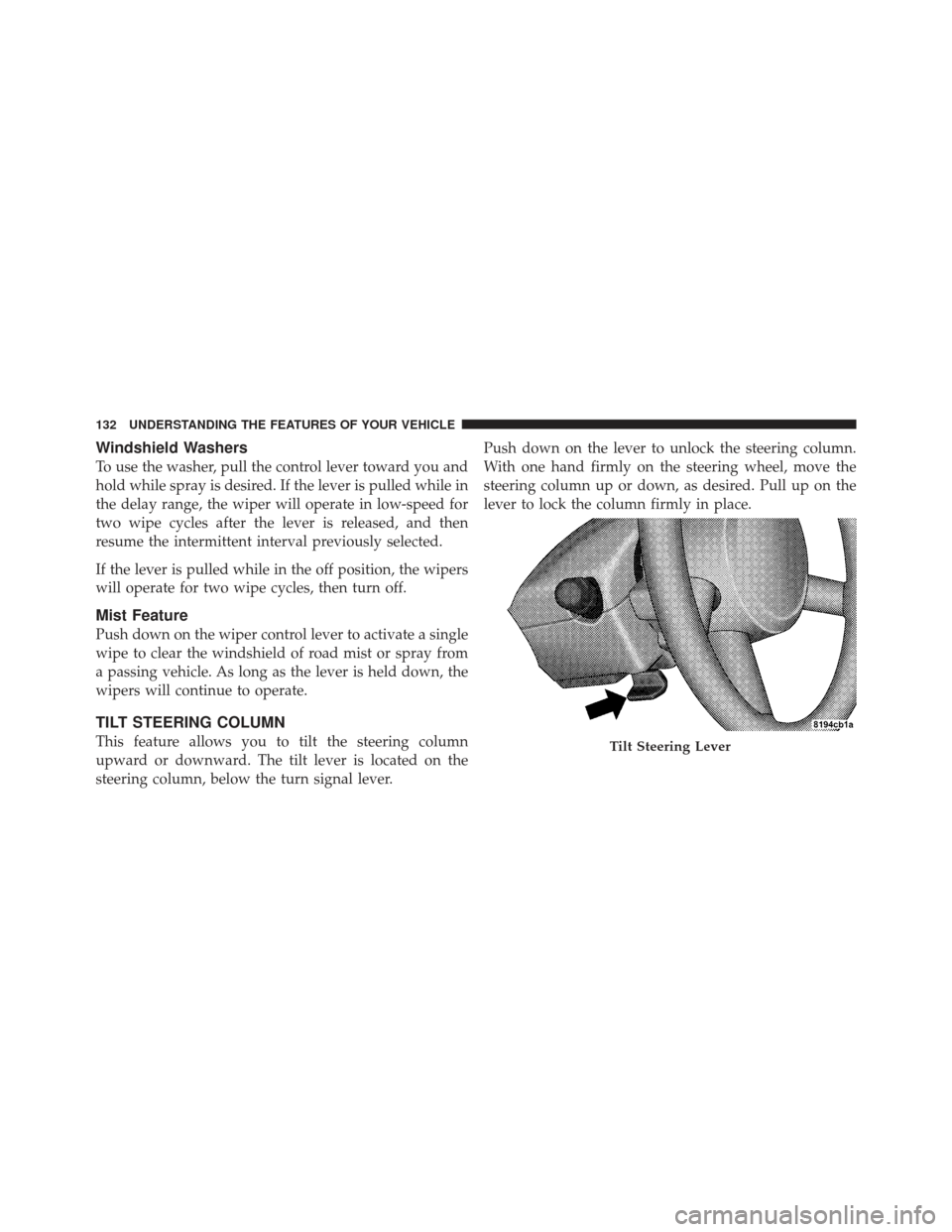
TILT STEERING COLUMN
This feature allows you to tilt the steering column
upward or downward. The tilt lever is located on the
steering column, below the turn signal lever.Push down on the lever to unlock the steering column.
With one hand firmly on the steering wheel, move the
steering column up or down, as desired. Pull up on the
lever to lock the column firmly in place.Tilt Steering Lever
132 UNDERSTANDING THE FEATURES OF YOUR VEHICLE
Page 136 of 410

To Activate
Push the ON/OFF button. The CRUISE indicator in the
instrument cluster will illuminate. To turn the system off,
push the ON/OFF button a second time. The CRUISE
indicator will turn off. The system should be turned off
when not in use.
WARNING!
Leaving the Electronic Speed Control system on
when not in use is dangerous. You could accidentally
set the system or cause it to go faster than you want.
You could lose control and have an accident. Always
leave the system off when you are not using it.
To Set a Desired Speed
When the vehicle has reached the desired speed, pull
down on the lever and release. Release the accelerator
and the vehicle will operate at the selected speed.NOTE:
The vehicle should be traveling at a steady
speed and on level ground before pressing the SET lever.
While in the AutoStick� mode, Electronic Speed Control
will only operate in 3rd and 4th gear.
To Deactivate
A soft tap on the brake pedal, pulling the Electronic
Speed Control lever toward CANCEL, or normal brake
or clutch pressure while slowing the vehicle will deacti-
vate Electronic Speed Control without erasing the set
speed memory. Pressing the ON/OFF button or turning
off the ignition switch erases the set speed memory.
To Resume Speed
To resume a previously set speed, pull the RESUME
ACCEL lever up and release. Resume can be used at any
speed above 20 mph (32 km/h).
134 UNDERSTANDING THE FEATURES OF YOUR VEHICLE
Page 166 of 410

INSTRUMENT CLUSTER DESCRIPTIONS
1. Fuel Gauge
When the ignition switch is in the ON position, the
pointer will show the level of fuel remaining in the fuel
tank.
2. Fuel Door Reminder
This is a reminder that the Fuel Filler Door is located on
the front passenger’s (right) side of the vehicle.
3. Temperature Gauge
The temperature gauge shows engine coolant tempera-
ture. Any reading within the normal range indicates that
the engine cooling system is operating satisfactorily.The gauge pointer will likely indicate a higher tempera-
ture when driving in hot weather, up mountain grades,
or when towing a trailer. It should not be allowed to
exceed the upper limits of the normal operating range.
CAUTION!
Driving with a hot engine cooling system could
damage your vehicle. If temperature gauge reads “H”
pull over and stop the vehicle. Idle the vehicle with
the air conditioner turned off until the pointer drops
back into the normal range. If the pointer remains on
the “H” and you hear continuous chimes, turn the
engine off immediately, and call an authorized deal-
ership for service.
164 UNDERSTANDING YOUR INSTRUMENT PANEL
Page 170 of 410

GASCAP
If the vehicle diagnostic system detects a leak or change
in the evaporative system, or the fuel filler cap is loose,
improperly installed, or damaged, the words “GASCAP”
will display in the odometer. If this occurs, tighten the
fuel filler cap properly and press the odometer reset
button to turn off the “GASCAP” message. (Refer to
“Onboard Diagnostic System — OBDII” in Section 7 of
this manual for more information). If the problem con-
tinues, the message will appear the next time the vehicle
is started. See your authorized dealer service center as
soon as possible.
9. Cruise Indicator — If EquippedThis indicator shows that the Electronic Speed
Control system is ON.
NOTE: The word “SET” will notilluminate when the
Electronic Speed Control System is on. 10. Malfunction Indicator Light (MIL)
The Malfunction Indicator Light (MIL) is part of
an onboard diagnostic system, called OBD, that
monitors engine and automatic transmission con-
trol systems. The light will illuminate when the key is in
the ON position, before engine start. If the bulb does not
come on when turning the key from OFF to ON, have the
condition checked promptly.
Certain conditions such as a loose or missing gas cap,
poor fuel quality, etc., may illuminate the MIL after
engine start. The vehicle should be serviced if the light
stays on through several of your typical driving cycles. In
most situations, the vehicle will drive normally and will
not require towing.
If the MIL flashes when the engine is running, serious
conditions may exist that could lead to immediate loss of
power or severe catalytic converter damage. The vehicle
should be serviced as soon as possible if this occurs.
168 UNDERSTANDING YOUR INSTRUMENT PANEL
Page 175 of 410

22. Oil Pressure Warning LightThis light indicates low engine oil pressure. The
light should turn on momentarily when the engine
is started. If the light turns on while driving, stop the
vehicle and shut off the engine as soon as possible. A
chime will sound for four minutes when this light turns
on.
Do not operate the vehicle until the cause is corrected.
This light does not indicate how much oil is in the engine.
The engine oil level must be checked under the hood.
23. Airbag Warning Light This light turns on and remains on for seven
seconds as a bulb check when the ignition
switch is first turned ON. If the light is not on
during starting, stays on, or turns on while
driving, have the system inspected by an authorized
dealer as soon as possible. 24. High Beam Indicator
This indicator shows that the high beam head-
lights are on. Push the multifunction lever forward
to switch the headlights to high beam, and pull toward
yourself (normal position) to return to low beam.
25. Compass Mini-Trip Computer (CMTC) or Electronic
Vehicle Information Center (EVIC) Button—If Equipped
Pushing this button will switch between the different
EVIC functions.
Press the CMTC reset button to scroll through sub-menus
(i.e., Trip Functions: AVG Fuel Economy, DTE Elapsed
Time, and Units).
26. Compass Mini-Trip Computer (CMTC) or Electronic
Vehicle Information Center (EVIC) Display — If
Equipped
On vehicles equipped with Electronic Vehicle Informa-
tion Center (EVIC), when the appropriate conditions
4
UNDERSTANDING YOUR INSTRUMENT PANEL 173
Page 218 of 410

CAUTION!
If the Defroster is not working the windshield and
windows may become fogged, and your visibility
will be greatly diminished. See your authorized
dealer as soon as possible.
Air Outlets
The airflow from each of the instrument panel outlets can
be adjusted for direction and turned on or off to control
airflow.
NOTE:For maximum airflow to the rear seat passen-
gers, the center instrument panel outlets can be aimed, so
that the left center outlet is directed toward the right rear
passenger and the right center outlet is directed toward
the left rear passenger.
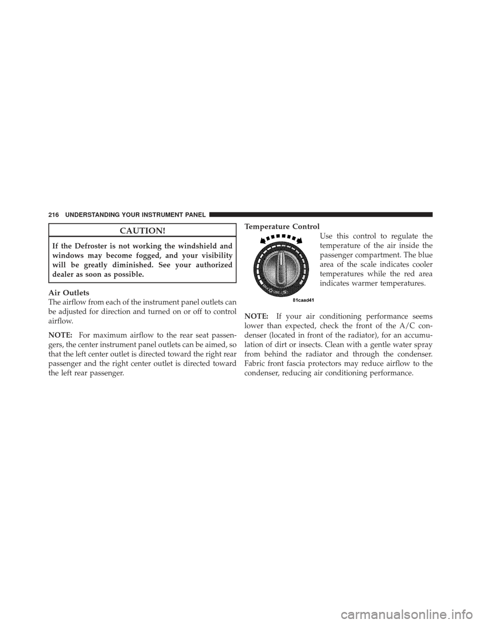
Temperature Control
Use this control to regulate the
temperature of the air inside the
passenger compartment. The blue
area of the scale indicates cooler
temperatures while the red area
indicates warmer temperatures.
NOTE: If your air conditioning performance seems
lower than expected, check the front of the A/C con-
denser (located in front of the radiator), for an accumu-
lation of dirt or insects. Clean with a gentle water spray
from behind the radiator and through the condenser.
Fabric front fascia protectors may reduce airflow to the
condenser, reducing air conditioning performance.
216 UNDERSTANDING YOUR INSTRUMENT PANEL