2009 CHEVROLET SILVERADO ESP
[x] Cancel search: ESPPage 399 of 600
The ITBC system is a factory installed item.
Out-of-factory installation of this system should not be
attempted. GM is not responsible for warranty or
performance of the system resulting from out-of-factory
installation.
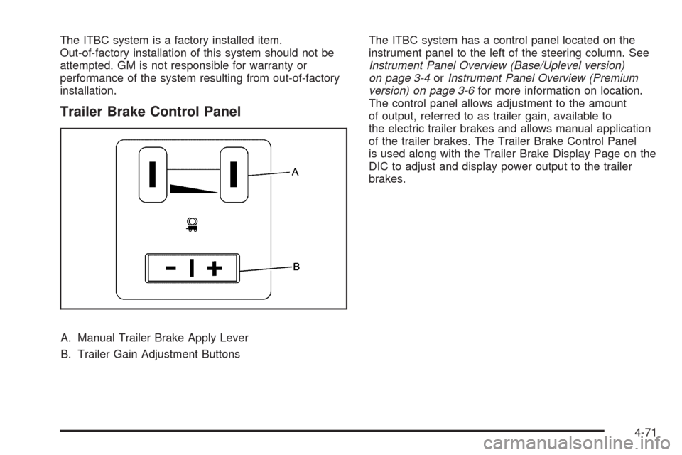
Trailer Brake Control Panel
A. Manual Trailer Brake Apply Lever
B. Trailer Gain Adjustment ButtonsThe ITBC system has a control panel located on the
instrument panel to the left of the steering column. See
Instrument Panel Overview (Base/Uplevel version)
on page 3-4orInstrument Panel Overview (Premium
version) on page 3-6for more information on location.
The control panel allows adjustment to the amount
of output, referred to as trailer gain, available to
the electric trailer brakes and allows manual application
of the trailer brakes. The Trailer Brake Control Panel
is used along with the Trailer Brake Display Page on the
DIC to adjust and display power output to the trailer
brakes.
4-71
Page 405 of 600
Towing a trailer requires a certain amount of experience.
Get to know the rig before setting out for the open
road. Get acquainted with the feel of handling and
braking with the added weight of the trailer. And always
keep in mind that the vehicle you are driving is now
longer and not as responsive as the vehicle is by itself.
Before starting, check all trailer hitch parts and
attachments, safety chains, electrical connectors, lamps,
tires and mirror adjustments. If the trailer has electric
brakes, start the vehicle and trailer moving and
then apply the trailer brake controller by hand to be sure
the brakes are working. This checks the electrical
connection at the same time.
During the trip, check occasionally to be sure that the
load is secure, and that the lamps and any trailer brakes
are still working.
While towing a trailer or when exposed to long periods
of sunshine, the �oor of the truck bed may become
very warm. Avoid putting items in the truck bed
that might be affected by high ambient temperatures.
Following Distance
Stay at least twice as far behind the vehicle ahead as
you would when driving the vehicle without a trailer. This
can help to avoid situations that require heavy braking
and sudden turns.
Passing
More passing distance is needed when towing a trailer.
Because the rig is longer, it is necessary to go much
farther beyond the passed vehicle before returning to
the lane.
Backing Up
Hold the bottom of the steering wheel with one hand.
Then, to move the trailer to the left, move that hand
to the left. To move the trailer to the right, move your
hand to the right. Always back up slowly and, if possible,
have someone guide you.
Making Turns
Notice:Making very sharp turns while trailering
could cause the trailer to come in contact with the
vehicle. The vehicle could be damaged. Avoid
making very sharp turns while trailering.
When turning with a trailer, make wider turns than
normal. Do this so the trailer will not strike soft
shoulders, curbs, road signs, trees or other objects.
Avoid jerky or sudden maneuvers. Signal well in
advance.
4-77
Page 408 of 600
Leaving After Parking on a Hill
1. Apply and hold the brake pedal while you:
Start the engine
Shift into a gear
Release the parking brake
2. Let up on the brake pedal.
3. Drive slowly until the trailer is clear of the chocks.
4. Stop and have someone pick up and store the
chocks.
Maintenance When Trailer Towing
The vehicle needs service more often when pulling a
trailer. See this manual’s Maintenance Schedule
or Index for more information. Things that are especially
important in trailer operation are automatic transmission
�uid, engine oil, axle lubricant, belts, cooling system
and brake system. It is a good idea to inspect
these before and during the trip.
Check periodically to see that all hitch nuts and bolts
are tight.
Trailer Wiring Harness
The vehicle is equipped with one of the following wiring
harnesses for towing a trailer or hauling a slide-in
camper.
Basic Trailer Wiring
All regular, extended cab and crew cab pickups have a
seven-wire trailer towing harness.
For vehicles not equipped with heavy duty trailering, the
harness is secured to the vehicle’s frame behind the
spare tire mount. The harness requires the installation of
a trailer connector, which is available through your
dealer/retailer.
If towing a light-duty trailer with a standard four-way
round pin connector, an adapter is available from your
dealer/retailer.
4-80
Page 434 of 600
How to Check Automatic Transmission
Fluid
Because this operation can be a little difficult, you may
choose to have this done at the dealer/retailer service
department.
If you do it yourself, be sure to follow all the instructions
here or you could get a false reading on the dipstick.
Notice:Too much or too little �uid can damage your
transmission. Too much can mean that some of the
�uid could come out and fall on hot engine parts or
exhaust system parts, starting a �re. Too little �uid
could cause the transmission to overheat. Be sure
to get an accurate reading if you check your
transmission �uid.
Wait at least 30 minutes before checking the
transmission �uid level if you have been driving:
When outside temperatures are above 90°F (32°C).
At high speed for quite a while.
In heavy traffic — especially in hot weather.
While pulling a trailer.
To get the right reading, the �uid should be at normal
operating temperature, which is 180°F to 200°F
(82°C to 93°C).Get the vehicle warmed up by driving about 15 miles
(24 km) when outside temperatures are above 50°F
(10°C). If it is colder than 50°F (10°C), drive the vehicle
in 3 (Third) until the engine temperature gage moves
and then remains steady for 10 minutes.
A cold �uid check can be made after the vehicle has
been sitting for eight hours or more with the engine off,
but this is used only as a reference. Let the engine
run at idle for �ve minutes if outside temperatures are
50°F (10°C) or more. If it is colder than 50°F (10°C), you
may have to idle the engine longer. Should the �uid
level be low during this cold check, you must check the
�uid hot before adding �uid. Checking the �uid hot
will give you a more accurate reading of the �uid level.
Checking the Fluid Level
Prepare the vehicle as follows:
1. Park the vehicle on a level place. Keep the engine
running.
2. With the parking brake applied, place the shift lever
in P (Park).
3. With your foot on the brake pedal, move the shift
lever through each gear range, pausing for about
three seconds in each range. Then, position
the shift lever in P (Park).
4. Let the engine run at idle for three minutes or more.
5-22
Page 457 of 600
Notice:If the other vehicle’s system is not a 12-volt
system with a negative ground, both vehicles can
be damaged. Only use vehicles with 12-volt systems
with negative grounds to jump start your vehicle.
2. If you have a vehicle with a diesel engine with
two batteries, you should know before you begin
that, especially in cold weather, you may not be
able to get enough power from a single battery
in another vehicle to start your diesel engine. If your
vehicle has more than one battery, use the battery
that is closer to the starter -- this will reduce
electrical resistance. This is located on the
passenger side, in the rear of the engine
compartment.
3. Get the vehicles close enough so the jumper cables
can reach, but be sure the vehicles are not touching
each other. If they are, it could cause an unwanted
ground connection. You would not be able to start
your vehicle, and the bad grounding could damage
the electrical systems.
To avoid the possibility of the vehicles rolling, set the
parking brake �rmly on both vehicles involved in the
jump start procedure. Put the automatic transmission
in P (Park) or a manual transmission in Neutral
before setting the parking brake. If you have a
four-wheel-drive vehicle, be sure the transfer
case is in a drive gear, not in Neutral.Notice:If you leave the radio or other accessories
on during the jump starting procedure, they could be
damaged. The repairs would not be covered by the
warranty. Always turn off the radio and other
accessories when jump starting the vehicle.
4. Turn off the ignition on both vehicles. Unplug
unnecessary accessories plugged into the cigarette
lighter or the accessory power outlets. Turn off the
radio and all the lamps that are not needed. This will
avoid sparks and help save both batteries. And it
could save the radio!
5. Open the hood on the other vehicle and locate the
positive (+) and negative (−) terminal locations on
that vehicle.
The positive (+) terminal, is located under a red
plastic cover at the positive battery post. To uncover
the positive (+) terminal, open the red plastic cover.
5-45
Page 483 of 600
Cold Tire Pressure:The amount of air pressure in
a tire, measured in pounds per square inch (psi) or
kilopascals (kPa) before a tire has built up heat
from driving. SeeInflation - Tire Pressure on
page 5-73.
Curb Weight
:The weight of a motor vehicle with
standard and optional equipment including the
maximum capacity of fuel, oil, and coolant,
but without passengers and cargo.
DOT Markings
:A code molded into the sidewall
of a tire signifying that the tire is in compliance
with the U.S. Department of Transportation (DOT)
motor vehicle safety standards. The DOT code
includes the Tire Identi�cation Number (TIN),
an alphanumeric designator which can also identify
the tire manufacturer, production plant, brand,
and date of production.
GVWR
:Gross Vehicle Weight Rating. See
Loading the Vehicle on page 4-32.
GAWR FRT
:Gross Axle Weight Rating for the
front axle. SeeLoading the Vehicle on page 4-32.
GAWR RR
:Gross Axle Weight Rating for the
rear axle. SeeLoading the Vehicle on page 4-32.
Intended Outboard Sidewall
:The side of an
asymmetrical tire, that must always face outward
when mounted on a vehicle.Kilopascal (kPa)
:The metric unit for air pressure.
Light Truck (LT-Metric) Tire
:A tire used on
light duty trucks and some multipurpose passenger
vehicles.
Load Index
:An assigned number ranging from
1 to 279 that corresponds to the load carrying
capacity of a tire.
Maximum In�ation Pressure
:The maximum air
pressure to which a cold tire can be in�ated.
The maximum air pressure is molded onto the
sidewall.
Maximum Load Rating
:The load rating for a tire
at the maximum permissible in�ation pressure
for that tire.
Maximum Loaded Vehicle Weight
:The sum of
curb weight, accessory weight, vehicle capacity
weight, and production options weight.
Normal Occupant Weight
:The number of
occupants a vehicle is designed to seat multiplied
by 150 lbs (68 kg). SeeLoading the Vehicle on
page 4-32.
Occupant Distribution
:Designated seating
positions.
5-71
Page 485 of 600
Vehicle Maximum Load on the Tire:Load on
an individual tire due to curb weight, accessory
weight, occupant weight, and cargo weight.
Vehicle Placard
:A label permanently attached
to a vehicle showing the vehicle’s capacity
weight and the original equipment tire size
and recommended in�ation pressure. See
“Tire and Loading Information Label” under
Loading the Vehicle on page 4-32.
In�ation - Tire Pressure
Tires need the correct amount of air pressure to
operate effectively.
Notice:Do not let anyone tell you that
under-in�ation or over-in�ation is all right. It is
not. If your tires do not have enough air
(under-in�ation), you can get the following:
Too much �exing
Too much heat
Tire overloading
Premature or irregular wear
Poor handling
Reduced fuel economyIf your tires have too much air (over-in�ation),
you can get the following:
Unusual wear
Poor handling
Rough ride
Needless damage from road hazards
A vehicle speci�c Tire and Loading Information
label is attached to your vehicle. This label shows
your vehicle’s original equipment tires and the
correct in�ation pressures for your tires when they
are cold. The recommended cold tire in�ation
pressure, shown on the label, is the minimum
amount of air pressure needed to support
your vehicle’s maximum load carrying capacity.
For additional information regarding how much
weight your vehicle can carry, and an example of
the Tire and Loading Information label, seeLoading
the Vehicle on page 4-32. How you load your
vehicle affects vehicle handling and ride comfort.
Never load your vehicle with more weight than it
was designed to carry.
When to Check
Check your tires once a month or more.
Do not forget to check the pressure of the spare
tire, if your vehicle has one. SeeSpare Tire
on page 5-114for additional information.
5-73
Page 488 of 600
Tire Pressure Monitor System
The Tire Pressure Monitor System (TPMS) uses radio
and sensor technology to check tire pressure levels.
The TPMS sensors monitor the air pressure in your
vehicle’s tires and transmit tire pressure readings to
a receiver located in the vehicle.
Each tire, including the spare (if provided), should be
checked monthly when cold and in�ated to the in�ation
pressure recommended by the vehicle manufacturer
on the vehicle placard or tire in�ation pressure label.
(If your vehicle has tires of a different size than the
size indicated on the vehicle placard or tire in�ation
pressure label, you should determine the proper
tire in�ation pressure for those tires.)
As an added safety feature, your vehicle has been
equipped with a tire pressure monitoring system (TPMS)
that illuminates a low tire pressure telltale when one
or more of your tires is signi�cantly under-in�ated.
Accordingly, when the low tire pressure telltale
illuminates, you should stop and check your tires
as soon as possible, and in�ate them to the proper
pressure. Driving on a signi�cantly under-in�ated
tire causes the tire to overheat and can lead to tire
failure. Under-in�ation also reduces fuel efficiency and
tire tread life, and may affect the vehicle’s handling
and stopping ability.Please note that the TPMS is not a substitute for proper
tire maintenance, and it is the driver’s responsibility to
maintain correct tire pressure, even if under-in�ation has
not reached the level to trigger illumination of the
TPMS low tire pressure telltale.
Your vehicle has also been equipped with a TPMS
malfunction indicator to indicate when the system is
not operating properly. The TPMS malfunction indicator
is combined with the low tire pressure telltale. When
the system detects a malfunction, the telltale will
�ash for approximately one minute and then remain
continuously illuminated. This sequence will continue
upon subsequent vehicle start-ups as long as the
malfunction exists.
When the malfunction indicator is illuminated, the system
may not be able to detect or signal low tire pressure as
intended. TPMS malfunctions may occur for a variety
of reasons, including the installation of replacement or
alternate tires or wheels on the vehicle that prevent the
TPMS from functioning properly. Always check the TPMS
malfunction telltale after replacing one or more tires or
wheels on your vehicle to ensure that the replacement or
alternate tires and wheels allow the TPMS to continue to
function properly.
SeeTire Pressure Monitor Operation on page 5-77for
additional information.
5-76