Page 315 of 408

When It Is Time for New Tires
Various factors, such as maintenance, temperatures,
driving speeds, vehicle loading, and road conditions,
influence when you need new tires.
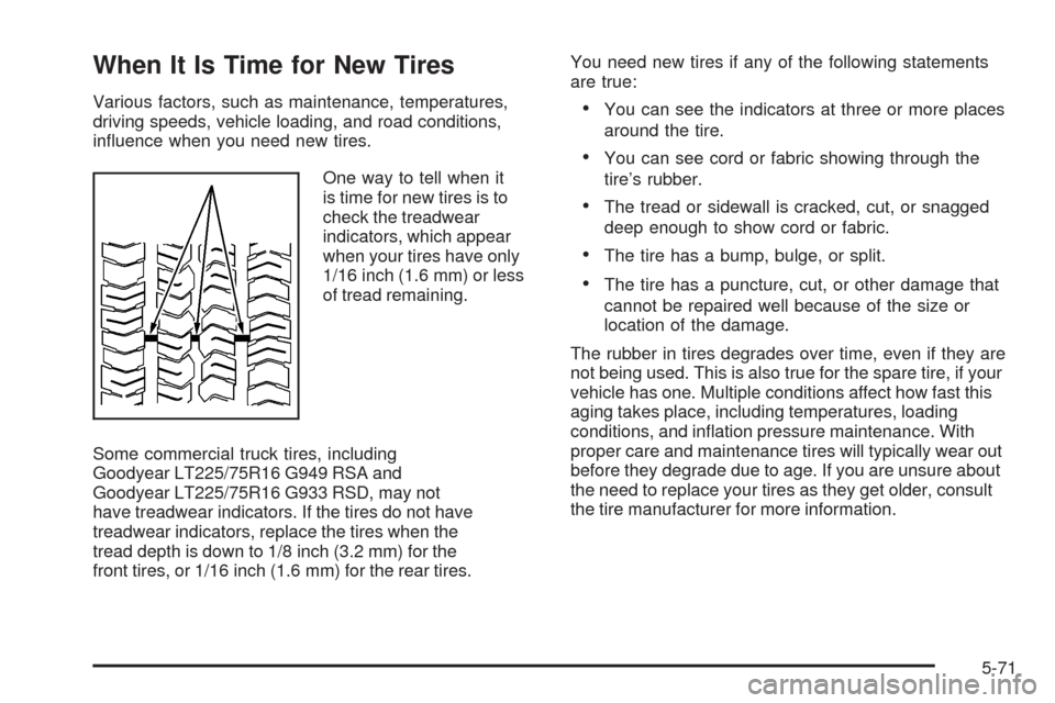
One way to tell when it
is time for new tires is to
check the treadwear
indicators, which appear
when your tires have only
1/16 inch (1.6 mm) or less
of tread remaining.
Some commercial truck tires, including
Goodyear LT225/75R16 G949 RSA and
Goodyear LT225/75R16 G933 RSD, may not
have treadwear indicators. If the tires do not have
treadwear indicators, replace the tires when the
tread depth is down to 1/8 inch (3.2 mm) for the
front tires, or 1/16 inch (1.6 mm) for the rear tires.You need new tires if any of the following statements
are true:•You can see the indicators at three or more places
around the tire.
•You can see cord or fabric showing through the
tire’s rubber.
•The tread or sidewall is cracked, cut, or snagged
deep enough to show cord or fabric.
•The tire has a bump, bulge, or split.
•The tire has a puncture, cut, or other damage that
cannot be repaired well because of the size or
location of the damage.
The rubber in tires degrades over time, even if they are
not being used. This is also true for the spare tire, if your
vehicle has one. Multiple conditions affect how fast this
aging takes place, including temperatures, loading
conditions, and inflation pressure maintenance. With
proper care and maintenance tires will typically wear out
before they degrade due to age. If you are unsure about
the need to replace your tires as they get older, consult
the tire manufacturer for more information.
5-71
Page 318 of 408

Uniform Tire Quality Grading
Quality grades can be found where applicable
on the tire sidewall between tread shoulder
and maximum section width. For example:
Treadwear 200 Traction AA
Temperature A
The following information relates to the system
developed by the United States National Highway
Traffic Safety Administration (NHTSA), which
grades tires by treadwear, traction, and
temperature performance. This applies only to
vehicles sold in the United States. The grades are
molded on the sidewalls of most passenger car
tires. The Uniform Tire Quality Grading (UTQG)
system does not apply to deep tread, winter-type
snow tires, space-saver, or temporary use
spare tires, tires with nominal rim diameters
of 10 to 12 inches (25 to 30 cm), or to some
limited-production tires.While the tires available on General Motors
passenger cars and light trucks may vary with
respect to these grades, they must also conform
to federal safety requirements and additional
General Motors Tire Performance Criteria (TPC)
standards.
Treadwear
The treadwear grade is a comparative rating
based on the wear rate of the tire when tested
under controlled conditions on a specified
government test course. For example, a tire
graded 150 would wear one and a half (1.5) times
as well on the government course as a tire
graded 100. The relative performance of tires
depends upon the actual conditions of their use,
however, and may depart significantly from the
norm due to variations in driving habits, service
practices, and differences in road characteristics
and climate.
5-74
Page 325 of 408
When the vehicle has a flat tire (B), use the following
example as a guide to assist you in the placement
of wheel blocks (A).
A. Wheel Block
B. Flat Tire
The following information explains how to use the jack
and change a tire.Removing the Spare Tire and Tools
If you have a cargo van or a passenger van, the
equipment you will need is located in the passenger
side rear corner of the vehicle.
Remove the retaining wing bolt and lift it off of the
mounting bracket.
If you have a van with the 15-passenger seating
arrangement, the equipment you will need is secured
on the rear floor of the passenger side of the vehicle.
5-81
Page 326 of 408
To access the equipment, remove the retaining wing
bolt and lift it out of the mounting bracket.The tools you will be using include the jack (A),
jack handle (B), hoist extension (C), jack handle
extension (D), and the wheel wrench (E).
The spare tire is mounted in the rear underbody of the
vehicle.
You will use the hoist extension, the jack handle
extensions and the wheel wrench to remove the
underbody-mounted spare tire.
5-82
Page 327 of 408
To lower the spare tire from the vehicle:
A. Spare Tire
B. Tire/Wheel Retainer
C. Hoist Cable
D. Hoist AssemblyE. Hoist Shaft
F. Jack Handle and
Hoist Extensions
G. Wheel Wrench1. Assemble the wheel wrench (G) to one or two of
the jack handle extensions and the hoist extension.
Insert the hoist extension end through the hole
in the rear bumper.
2. Be sure the hoist extension end connects to the
hoist shaft (E). The chiseled end of the extension
is used to lower the spare tire.
3. Turn the wheel wrench counterclockwise to lower
the spare tire to the ground. Continue to turn the
wheel wrench until the spare tire can be pulled out
from under the vehicle.
If the spare tire does not lower to the ground,
the secondary latch is engaged causing the tire
not to lower. SeeSecondary Latch System
on page 5-92.
5-83
Page 328 of 408
4. When the tire has been lowered, pull the tire toward
you so you can reach the tire retainer and pull it up
through the wheel opening.
If you have a vehicle which was completed from a
cab and chassis, refer to the information from
body supplier/installer.
The spare tire is a full-size tire, like the other tires
on the vehicle.
5. Put the spare tire near the flat tire.
Removing the Flat Tire and
Installing the Spare Tire
If your vehicle has plastic wheel nut caps, loosen
them by turning the wheel wrench counterclockwise.
The wheel nut caps are designed to remain with
the center cap. Remove the center cap.
If the wheel has a smooth center piece, place the chisel
end of the wheel wrench in the slot on the wheel and
gently pry it out.
1. Do a safety check before proceeding. SeeChanging
a Flat Tire on page 5-80for more information.
2. Loosen all the wheel nuts with the wheel wrench.
Do not remove them yet.
5-84
Page 331 of 408

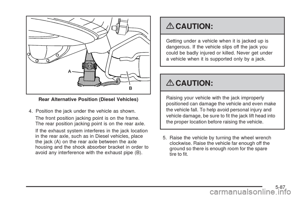
4. Position the jack under the vehicle as shown.
The front position jacking point is on the frame.
The rear position jacking point is on the rear axle.
If the exhaust system interferes in the jack location
in the rear axle, such as in Diesel vehicles, place
the jack (A) on the rear axle between the axle
housing and the shock absorber bracket in order to
avoid any interference with the exhaust pipe (B).
{CAUTION:
Getting under a vehicle when it is jacked up is
dangerous. If the vehicle slips off the jack you
could be badly injured or killed. Never get under
a vehicle when it is supported only by a jack.
{CAUTION:
Raising your vehicle with the jack improperly
positioned can damage the vehicle and even make
the vehicle fall. To help avoid personal injury and
vehicle damage, be sure to fit the jack lift head into
the proper location before raising the vehicle.
5. Raise the vehicle by turning the wheel wrench
clockwise. Raise the vehicle far enough off the
ground so there is enough room for the spare
tire to fit. Rear Alternative Position (Diesel Vehicles)
5-87
Page 336 of 408

Secondary Latch System
Your vehicle has an underbody-mounted tire hoist
assembly equipped with a secondary latch system.
It is designed to stop the spare tire from suddenly falling
off the vehicle if the cable holding the spare tire is
damaged. For the secondary latch to work, the tire
must be stowed with the valve stem pointing down.
SeeStoring a Flat or Spare Tire and Tools on page 5-95
for instructions on storing the spare tire correctly.
{CAUTION:
Before beginning this procedure read all the
instructions. Failure to read and follow the
instructions could damage the hoist assembly
and you and others could get hurt. Read and
follow the instructions listed next.To release the spare tire from the secondary latch:
{CAUTION:
Someone standing too close during the procedure
could be injured by the jack. If the spare tire does
not slide off the jack completely, make sure no
one is behind you or on either side of you as you
pull the jack out from the under spare.
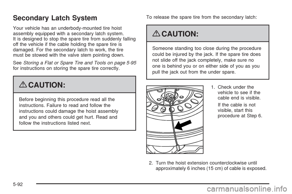
1. Check under the
vehicle to see if the
cable end is visible.
If the cable is not
visible, start this
procedure at Step 6.
2. Turn the hoist extension counterclockwise until
approximately 6 inches (15 cm) of cable is exposed.
5-92