Page 826 of 1903

Downloaded from www.Manualslib.com manuals search engine Crankshaft Position (CKP) Sensor
Description
The Crankshaft Position (CKP) sensor is located on the flywheel shell facing the gear teeth of the signal plate. It
detects the fluctuation of the engine revolution. The sensor consists of a permanent magnet and Induction coil.
Operation
When the engine is running, the high and low parts of the teeth cause the gap with the sensor to change. The
changing gap cause the magnetic field near the sensor to change. Due to the changing magnetic field, the voltage
from the sensor changes. The Engine Control Module (ECM) receives the voltage signal and detects the fluctuation
of the engine revolution.
Removal & Installation
1. Disconnect the negative battery cable.
2. Disconnect the crankshaft position sensor electricalconnector from the crankshaft position sensor.
3. Remove the accessory drive belt (See Accessory Drive Belt Removal & Installation in Section 02
Engine).
4. Remove the crankshaft pulley (See Crankshaft Pul- ley Removal & Installation in Section 02 Engine).
5. Remove the timing belt lower cover (See Timing Belt Lower Cover Removal & Installation in Section
02 Engine).
6. Remove the crankshaft position sensor retaining bolts (1).
(Tighten: Crankshaft position sensor retaining bolt
to 20 N·m)
7. Installation is in the order of removal.
ON-VEHICLE SERVICE
LTSM030012
03–542Chery Automobile Co., Ltd.
Page 1262 of 1903
Downloaded from www.Manualslib.com manuals search engine CLUTCH ASSEMBLY SERVICE
Clutch and Pressure Plate
Removal & Installation
1. Remove the transaxle assembly (See Transaxle Assembly Removal & Installation in Section 08 Transaxle).
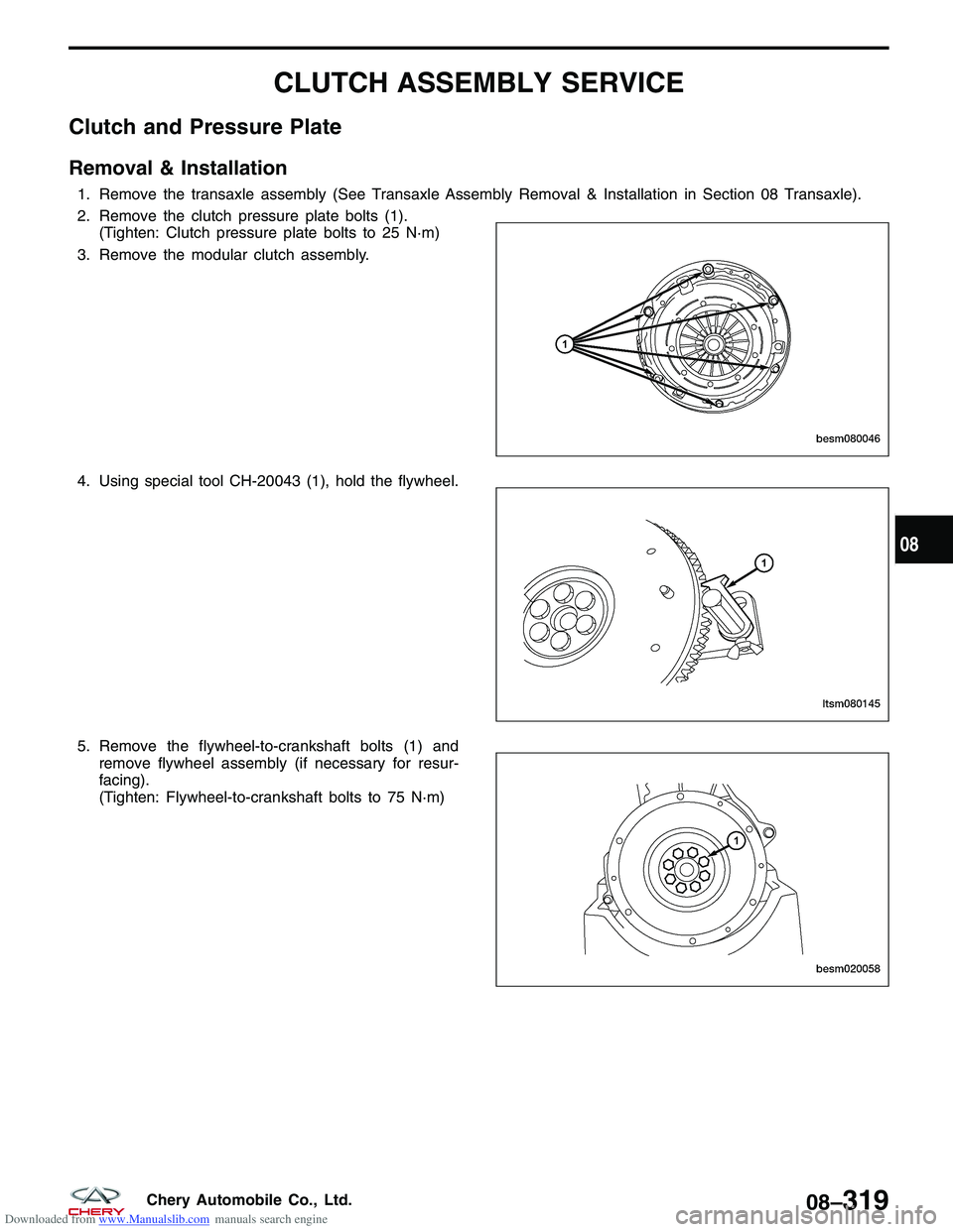
2. Remove the clutch pressure plate bolts (1).(Tighten: Clutch pressure plate bolts to 25 N·m)
3. Remove the modular clutch assembly.
4. Using special tool CH-20043 (1), hold the flywheel.
5. Remove the flywheel-to-crankshaft bolts (1) and remove flywheel assembly (if necessary for resur-
facing).
(Tighten: Flywheel-to-crankshaft bolts to 75 N·m)
BESM080046
LTSM080145
BESM020058
08
08–319Chery Automobile Co., Ltd.
Page 1263 of 1903
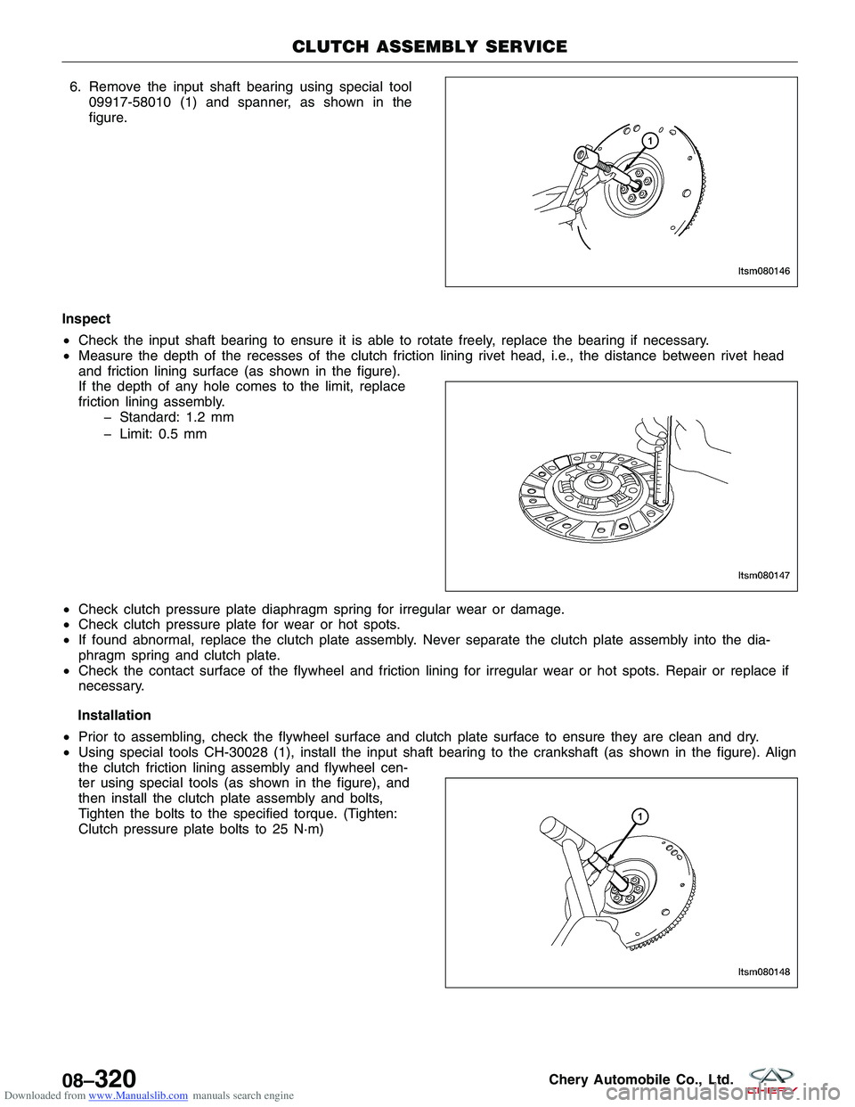
Downloaded from www.Manualslib.com manuals search engine 6. Remove the input shaft bearing using special tool09917-58010 (1) and spanner, as shown in the
figure.
Inspect
• Check the input shaft bearing to ensure it is able to rotate freely, replace the bearing if necessary.
• Measure the depth of the recesses of the clutch friction lining rivet head, i.e., the distance between rivet head
and friction lining surface (as shown in the figure).
If the depth of any hole comes to the limit, replace
friction lining assembly.
Standard: 1.2 mm
Limit: 0.5 mm
• Check clutch pressure plate diaphragm spring for irregular wear or damage.
• Check clutch pressure plate for wear or hot spots.
• If found abnormal, replace the clutch plate assembly. Never separate the clutch plate assembly into the dia-
phragm spring and clutch plate.
• Check the contact surface of the flywheel and friction lining for irregular wear or hot spots. Repair or replace if
necessary.
Installation
• Prior to assembling, check the flywheel surface and clutch plate surface to ensure they are clean and dry.
• Using special tools CH-30028 (1), install the input shaft bearing to the crankshaft (as shown in the figure). Align
the clutch friction lining assembly and flywheel cen-
ter using special tools (as shown in the figure), and
then install the clutch plate assembly and bolts,
Tighten the bolts to the specified torque. (Tighten:
Clutch pressure plate bolts to 25 N·m)
CLUTCH ASSEMBLY SERVICE
LTSM080146
LTSM080147
LTSM080148
08–320Chery Automobile Co., Ltd.
Page 1277 of 1903
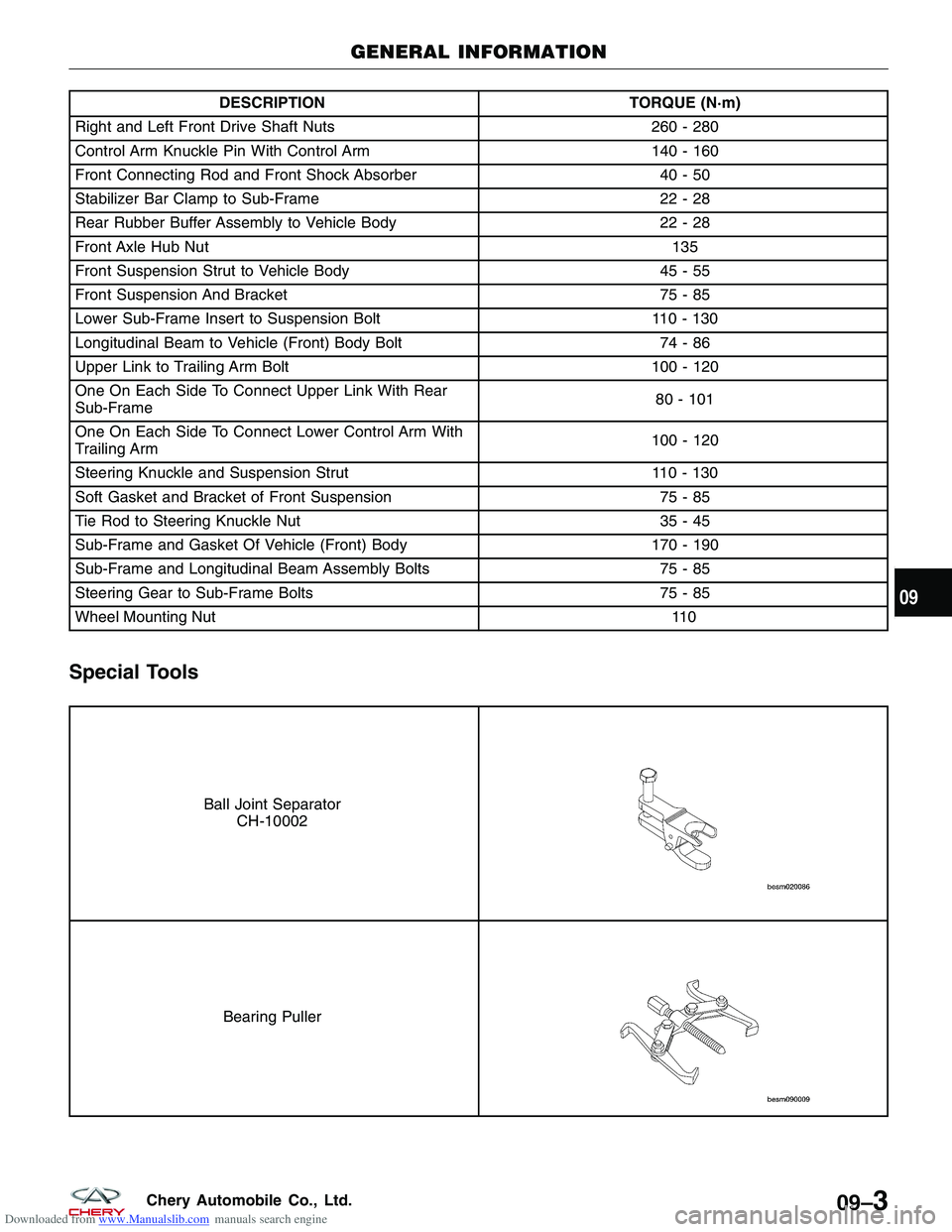
Downloaded from www.Manualslib.com manuals search engine DESCRIPTIONTORQUE (N·m)
Right and Left Front Drive Shaft Nuts 260 - 280
Control Arm Knuckle Pin With Control Arm 140 - 160
Front Connecting Rod and Front Shock Absorber 40 - 50
Stabilizer Bar Clamp to Sub-Frame 22 - 28
Rear Rubber Buffer Assembly to Vehicle Body 22 - 28
Front Axle Hub Nut 135
Front Suspension Strut to Vehicle Body 45 - 55
Front Suspension And Bracket 75 - 85
Lower Sub-Frame Insert to Suspension Bolt 110 - 130
Longitudinal Beam to Vehicle (Front) Body Bolt 74 - 86
Upper Link to Trailing Arm Bolt 100 - 120
One On Each Side To Connect Upper Link With Rear
Sub-Frame 80 - 101
One On Each Side To Connect Lower Control Arm With
Trailing Arm 100 - 120
Steering Knuckle and Suspension Strut 110 - 130
Soft Gasket and Bracket of Front Suspension 75 - 85
Tie Rod to Steering Knuckle Nut 35 - 45
Sub-Frame and Gasket Of Vehicle (Front) Body 170 - 190
Sub-Frame and Longitudinal Beam Assembly Bolts 75 - 85
Steering Gear to Sub-Frame Bolts 75 - 85
Wheel Mounting Nut \
\
11 0
Special Tools
Ball Joint Separator CH-10002
Bearing Puller
GENERAL INFORMATION
09
09–3Chery Automobile Co., Ltd.
Page 1280 of 1903
Downloaded from www.Manualslib.com manuals search engine Front Axle Shaft
Removal & Installation
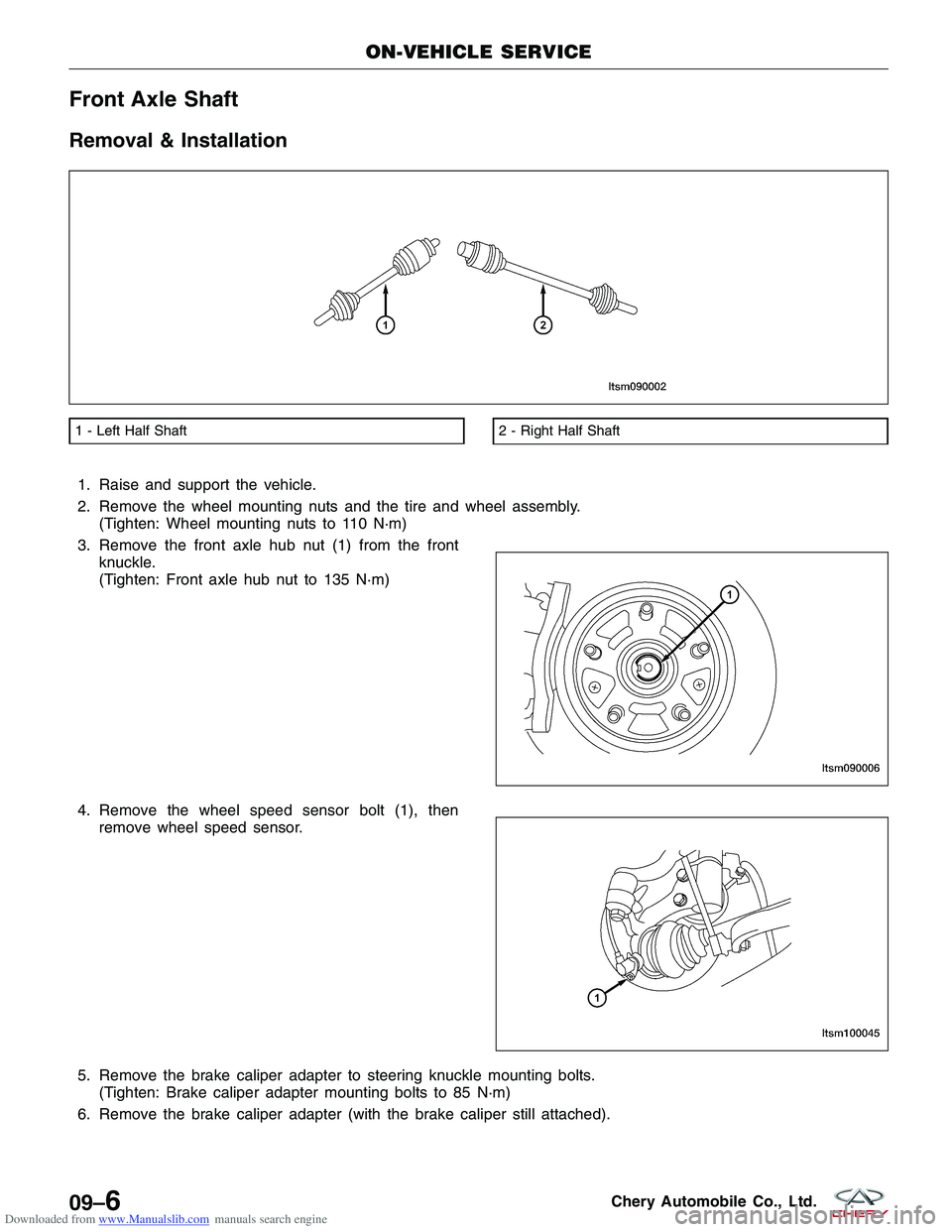
1. Raise and support the vehicle.
2. Remove the wheel mounting nuts and the tire and wheel assembly.(Tighten: Wheel mounting nuts to 110 N·m)
3. Remove the front axle hub nut (1) from the front knuckle.
(Tighten: Front axle hub nut to 135 N·m)
4. Remove the wheel speed sensor bolt (1), then remove wheel speed sensor.
5. Remove the brake caliper adapter to steering knuckle mounting bolts. (Tighten: Brake caliper adapter mounting bolts to 85 N·m)
6. Remove the brake caliper adapter (with the brake caliper still attached).
1 - Left Half Shaft2 - Right Half Shaft
ON-VEHICLE SERVICE
LTSM090002
LTSM090006
LTSM100045
09–6Chery Automobile Co., Ltd.
Page 1284 of 1903
Downloaded from www.Manualslib.com manuals search engine Specifications
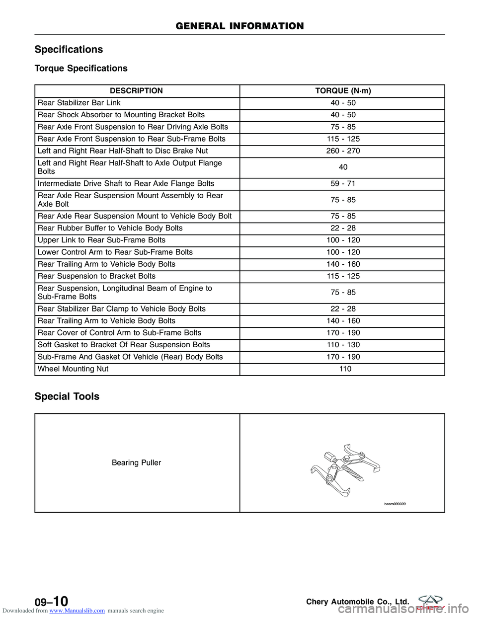
Torque Specifications
DESCRIPTIONTORQUE (N·m)
Rear Stabilizer Bar Link 40 - 50
Rear Shock Absorber to Mounting Bracket Bolts 40 - 50
Rear Axle Front Suspension to Rear Driving Axle Bolts 75 - 85
Rear Axle Front Suspension to Rear Sub-Frame Bolts 115 - 125
Left and Right Rear Half-Shaft to Disc Brake Nut 260 - 270
Left and Right Rear Half-Shaft to Axle Output Flange
Bolts 40
Intermediate Drive Shaft to Rear Axle Flange Bolts 59 - 71
Rear Axle Rear Suspension Mount Assembly to Rear
Axle Bolt 75-85
Rear Axle Rear Suspension Mount to Vehicle Body Bolt 75 - 85
Rear Rubber Buffer to Vehicle Body Bolts 22 - 28
Upper Link to Rear Sub-Frame Bolts 100 - 120
Lower Control Arm to Rear Sub-Frame Bolts 100 - 120
Rear Trailing Arm to Vehicle Body Bolts 140 - 160
Rear Suspension to Bracket Bolts 115 - 125
Rear Suspension, Longitudinal Beam of Engine to
Sub-Frame Bolts 75-85
Rear Stabilizer Bar Clamp to Vehicle Body Bolts 22 - 28
Rear Trailing Arm to Vehicle Body Bolts 140 - 160
Rear Cover of Control Arm to Sub-Frame Bolts 170 - 190
Soft Gasket to Bracket Of Rear Suspension Bolts 110 - 130
Sub-Frame And Gasket Of Vehicle (Rear) Body Bolts 170 - 190
Wheel Mounting Nut \
\
11 0
Special Tools
Bearing Puller
GENERAL INFORMATION
09–10Chery Automobile Co., Ltd.
Page 1285 of 1903
Downloaded from www.Manualslib.com manuals search engine DIAGNOSIS & TESTING
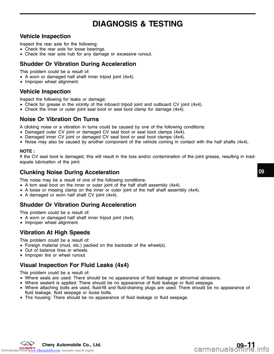
Vehicle Inspection
Inspect the rear axle for the following:
•Check the rear axle for loose bearings.
• Check the rear axle hub for any damage or excessive runout.
Shudder Or Vibration During Acceleration
This problem could be a result of:
•A worn or damaged half shaft inner tripod joint (4x4).
• Improper wheel alignment.
Vehicle Inspection
Inspect the following for leaks or damage:
•Check for grease in the vicinity of the inboard tripod joint and outboard CV joint (4x4).
• Check the inner or outer joint seal boot or seal boot clamp for damage (4x4).
Noise Or Vibration On Turns
A clicking noise or a vibration in turns could be caused by one of the following conditions:
•Damaged outer CV joint or damaged CV seal boot or seal boot clamps (4x4).
• Damaged inner CV joint or damaged CV seal boot or seal boot clamps (4x4).
• Noise may also be caused by another component of the vehicle coming in contact with the half shafts (4x4).
NOTE :
If the CV seal boot is damaged, this will result in the loss and/or contamination of the joint grease, resulting in inad-
equate lubrication of the joint.
Clunking Noise During Acceleration
This noise may be a result of one of the following conditions:
• A torn seal boot on the inner or outer joint of the half shaft assembly (4x4).
• A loose or missing clamp on the inner or outer joint of the half shaft assembly (4x4).
• A damaged or worn half shaft CV joint (4x4).
Shudder Or Vibration During Acceleration
This problem could be a result of:
•A worn or damaged half shaft inner tripod joint (4x4).
• Improper wheel alignment.
Vibration At High Speeds
This problem could be a result of:
•Foreign material (mud, etc.) packed on the backside of the wheel(s).
• Out of balance tires or wheels.
• Improper tire or wheel runout.
Visual Inspection For Fluid Leaks (4x4)
This problem could be a result of:
•Where seals are used: There should be no appearance of fluid leakage or abnormal abrasions.
• Where sealant is applied: There should be no appearance of fluid leakage or fluid seepage.
• Where attaching bolts are used, fluid-fill and fluid-draining plugs are used: There should be no appearance of
fluid leakage, fluid seepage or loose bolts.
• The housing: There should be no appearance of fluid leakage or fluid seepage.
09
09–11Chery Automobile Co., Ltd.
Page 1293 of 1903
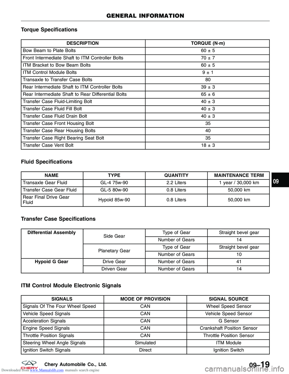
Downloaded from www.Manualslib.com manuals search engine Torque Specifications
DESCRIPTIONTORQUE (N·m)
Bow Beam to Plate Bolts 60 ± 5
Front Intermediate Shaft to ITM Controller Bolts 70 ± 7
ITM Bracket to Bow Beam Bolts 60 ± 5
ITM Control Module Bolts 9 ± 1
Transaxle to Transfer Case Bolts 80
Rear Intermediate Shaft to ITM Controller Bolts 39 ± 3
Rear Intermediate Shaft to Rear Differential Bolts 65 ± 6
Transfer Case Fluid-Limiting Bolt 40 ± 3
Transfer Case Fluid Fill Bolt 40 ± 3
Transfer Case Fluid Drain Bolt 40 ± 3
Transfer Case Front Housing Bolt 35
Transfer Case Rear Housing Bolts 40
Transfer Case Right Bearing Seat Bolt 35
Transfer Case Vent Bolt 18 ± 3
Fluid Specifications
NAMETYPEQUANTITYMAINTENANCE TERM
Transaxle Gear Fluid GL-4 75w-902.2 Liters1 year / 30,000 km
Transfer Case Gear Fluid GL-5 80w-900.8 Liters50,000 km
Rear Final Drive Gear
Fluid Hypoid 85w-90
0.8 Liters50,000 km
Transfer Case Specifications
Differential Assembly
Side GearType of Gear Straight bevel gear
Number of Gears 14
Planetary Gear Type of Gear
Straight bevel gear
Number of Gears 10
Hypoid G Gear Drive GearNumber of Gears 41
Driven Gear Number of Gears 14
ITM Control Module Electronic Signals
SIGNALSMODE OF PROVISION SIGNAL SOURCE
Signals Of The Four Wheel Speed CANWheel Speed Sensor
Vehicle Speed Signals CANVehicle Speed Sensor
Acceleration Signals CANG Sensor
Engine Speed Signals CANCrankshaft Position Sensor
Throttle Position Signals CANThrottle Position Sensor
Steering Wheel Angle Signals SimulatedITM Module
Ignition Switch Signals DirectIgnition Switch
GENERAL INFORMATION
09
09–19Chery Automobile Co., Ltd.