Page 1622 of 1903

Downloaded from www.Manualslib.com manuals search engine BODY CONTROL MODULE - BCM
Description
The Body Control Module (BCM) is located behind the glove box. The BCM controls many electrical components and
systems for the vehicle electrical system. The BCM is the primary hub that controls functions such as internal and
external lighting, power windows and power door locks.
Operation
The Body Control Module (BCM) uses hard wired inputs from various sensors and switches. The sensors and
switches are located throughout the vehicle.
The following components are inputs to the BCM:
•Key switch
• Rear defroster switch
• Hazard lamp switch
• Power window switches
• Power door lock switches
• Seat belt switch
• Vehicle speed
• Door ajar switches
• Turn signal switch
The following components are outputs from the BCM:
• Key lamp
• Stop lamp relay
• Rear defroster grid
• Courtesy lamps
• Power window motor
• Power door lock motor
• Turn signal lamps
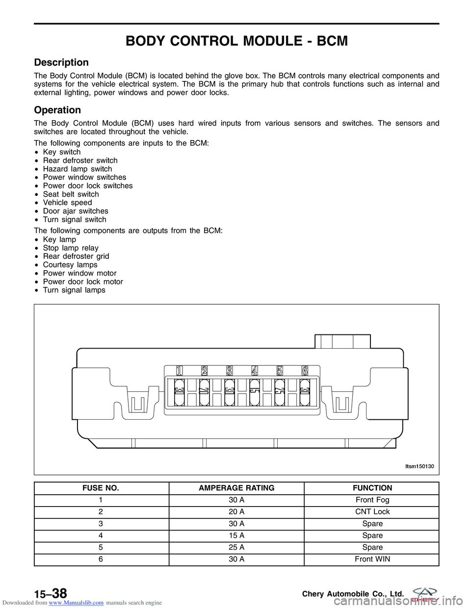
FUSE NO. AMPERAGE RATING FUNCTION
1 30 AFront Fog
2 20 ACNT Lock
3 30 A Spare
4 15 A Spare
5 25 A Spare
6 30 AFront WIN
LTSM150130
15–38Chery Automobile Co., Ltd.
Page 1628 of 1903
Downloaded from www.Manualslib.com manuals search engine ON-VEHICLE SERVICE
Body Control Module (BCM)
Removal & Installation
1. Disconnect the negative battery cable.
2. Remove the glove box mounting bolts (1).
3. Remove the BCM and ECM mounting bracket retaining bolts.
4. Remove the BCM mounting bolts (1).(Tighten: BCM mounting bolts to 5 N·m)
5. Disconnect the BCM electrical connector (2).
6. Remove the BCM.
7. Installation is in the reverse order of removal.
LTSM150086
LTSM150109
15–44Chery Automobile Co., Ltd.
Page 1630 of 1903
Downloaded from www.Manualslib.com manuals search engine 7. Remove the glove box retaining bolts (1).
8. Remove the bolts (1) under the glove box.
INSTRUMENT PANEL
LTSM150086
LTSM150087
15–46Chery Automobile Co., Ltd.
Page 1633 of 1903
Downloaded from www.Manualslib.com manuals search engine 15. Remove two instrument panel mounting nuts (1)and bolts (2) in the glove box.
16. Remove the A-pillar trim panel (See A-Pillar Removal & Installation in Section 15 Body & Accessories).
17. Remove the lower console (See Lower Console Removal & Installation in Section 15 Body & Accessories).
18. Carefully remove the instrument panel.
19. Installation is in the reverse order of removal.
INSTRUMENT PANEL
LTSM150092
15
15–49Chery Automobile Co., Ltd.