Page 1177 of 1903
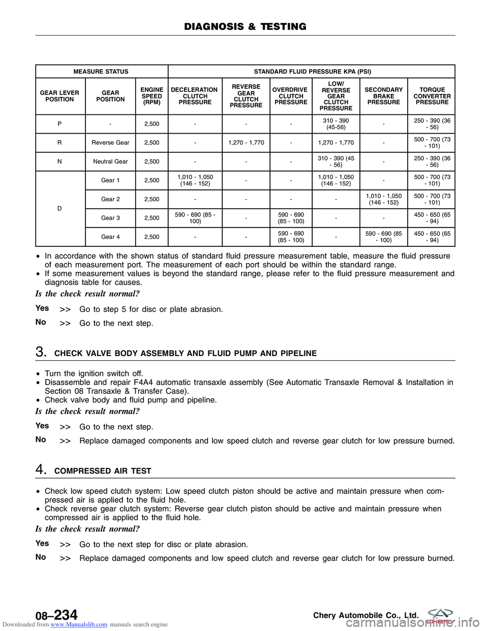
Downloaded from www.Manualslib.com manuals search engine MEASURE STATUSSTANDARD FLUID PRESSURE KPA (PSI)
GEAR LEVER POSITION GEAR
POSITION ENGINE
SPEED (RPM) DECELERATION
CLUTCH
PRESSURE REVERSE
GEAR
CLUTCH
PRESSURE OVERDRIVE
CLUTCH
PRESSURE LOW/
REVERSE GEAR
CLUTCH
PRESSURE SECONDARY
BRAKE
PRESSURE TORQUE
CONVERTER PRESSURE
P -2,500 - --310 - 390
(45-56) -250 - 390 (36
- 56)
R Reverse Gear 2,500 -1,270 - 1,770 - 1,270 - 1,770 - 500 - 700 (73
- 101)
N Neutral Gear 2,500 ---310 - 390 (45
- 56) -250 - 390 (36
- 56)
D Gear 1 2,500
1,010 - 1,050
(146 - 152) -- 1,010 - 1,050
(146 - 152) -500 - 700 (73
- 101)
Gear 2 2,500 ----1,010 - 1,050
(146 - 152) 500 - 700 (73
- 101)
Gear 3 2,500 590 - 690 (85 -
100) -590 - 690
(85 - 100) -- 450 - 650 (65
- 94)
Gear 4 2,500 --590 - 690
(85 - 100) -590 - 690 (85
- 100) 450 - 650 (65
- 94)
•In accordance with the shown status of standard fluid pressure measurement table, measure the fluid pressure
of each measurement port. The measurement of each port should be within the standard range.
• If some measurement values is beyond the standard range, please refer to the fluid pressure measurement and
diagnosis table for causes.
Is the check result normal?
Ye s>>Go to step 5 for disc or plate abrasion.
No
>>Go to the next step.
3.CHECK VALVE BODY ASSEMBLY AND FLUID PUMP AND PIPELINE
• Turn the ignition switch off.
• Disassemble and repair F4A4 automatic transaxle assembly (See Automatic Transaxle Removal & Installation in
Section 08 Transaxle & Transfer Case).
• Check valve body and fluid pump and pipeline.
Is the check result normal?
Ye s>>Go to the next step.
No
>>Replace damaged components and low speed clutch and reverse gear clutch for low pressure burned.
4.COMPRESSED AIR TEST
• Check low speed clutch system: Low speed clutch piston should be active and maintain pressure when com-
pressed air is applied to the fluid hole.
• Check reverse gear clutch system: Reverse gear clutch piston should be active and maintain pressure when
compressed air is applied to the fluid hole.
Is the check result normal?
Ye s>>Go to the next step for disc or plate abrasion.
No
>>Replace damaged components and low speed clutch and reverse gear clutch for low pressure burned.
DIAGNOSIS & TESTING
08–234Chery Automobile Co., Ltd.
Page 1178 of 1903
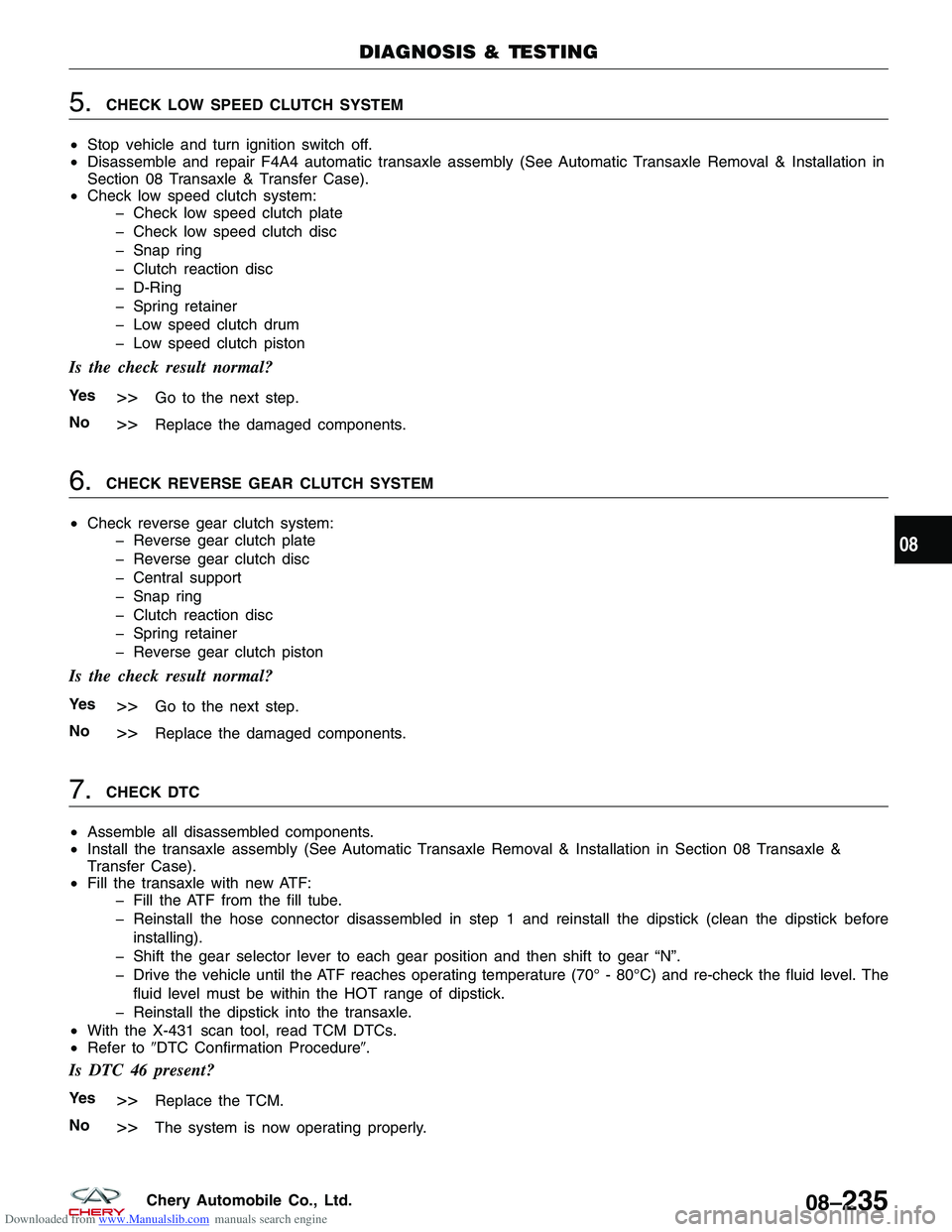
Downloaded from www.Manualslib.com manuals search engine 5.CHECK LOW SPEED CLUTCH SYSTEM
• Stop vehicle and turn ignition switch off.
• Disassemble and repair F4A4 automatic transaxle assembly (See Automatic Transaxle Removal & Installation in
Section 08 Transaxle & Transfer Case).
• Check low speed clutch system:
� Check low speed clutch plate
� Check low speed clutch disc
� Snap ring
� Clutch reaction disc
� D-Ring
� Spring retainer
� Low speed clutch drum
� Low speed clutch piston
Is the check result normal?
Ye s>>Go to the next step.
No
>>Replace the damaged components.
6.CHECK REVERSE GEAR CLUTCH SYSTEM
• Check reverse gear clutch system:
� Reverse gear clutch plate
� Reverse gear clutch disc
� Central support
� Snap ring
� Clutch reaction disc
� Spring retainer
� Reverse gear clutch piston
Is the check result normal?
Ye s>>Go to the next step.
No
>>Replace the damaged components.
7.CHECK DTC
• Assemble all disassembled components.
• Install the transaxle assembly (See Automatic Transaxle Removal & Installation in Section 08 Transaxle &
Transfer Case).
• Fill the transaxle with new ATF:
� Fill the ATF from the fill tube.
� Reinstall the hose connector disassembled in step 1 and reinstall the dipstick (clean the dipstick before
installing).
� Shift the gear selector lever to each gear position and then shift to gear “N”.
� Drive the vehicle until the ATF reaches operating temperature (70° - 80°C) and re-check the fluid level. The fluid level must be within the HOT range of dipstick.
� Reinstall the dipstick into the transaxle.
• With the X-431 scan tool, read TCM DTCs.
• Refer to �DTC Confirmation Procedure�.
Is DTC 46 present?
Ye s>>Replace the TCM.
No
>>The system is now operating properly.
DIAGNOSIS & TESTING
08
08–235Chery Automobile Co., Ltd.
Page 1179 of 1903
Downloaded from www.Manualslib.com manuals search engine 54 - Electrical Relay Open Circuit
DIAGNOSIS & TESTING
LTSMW080003T
08–236Chery Automobile Co., Ltd.
Page 1180 of 1903
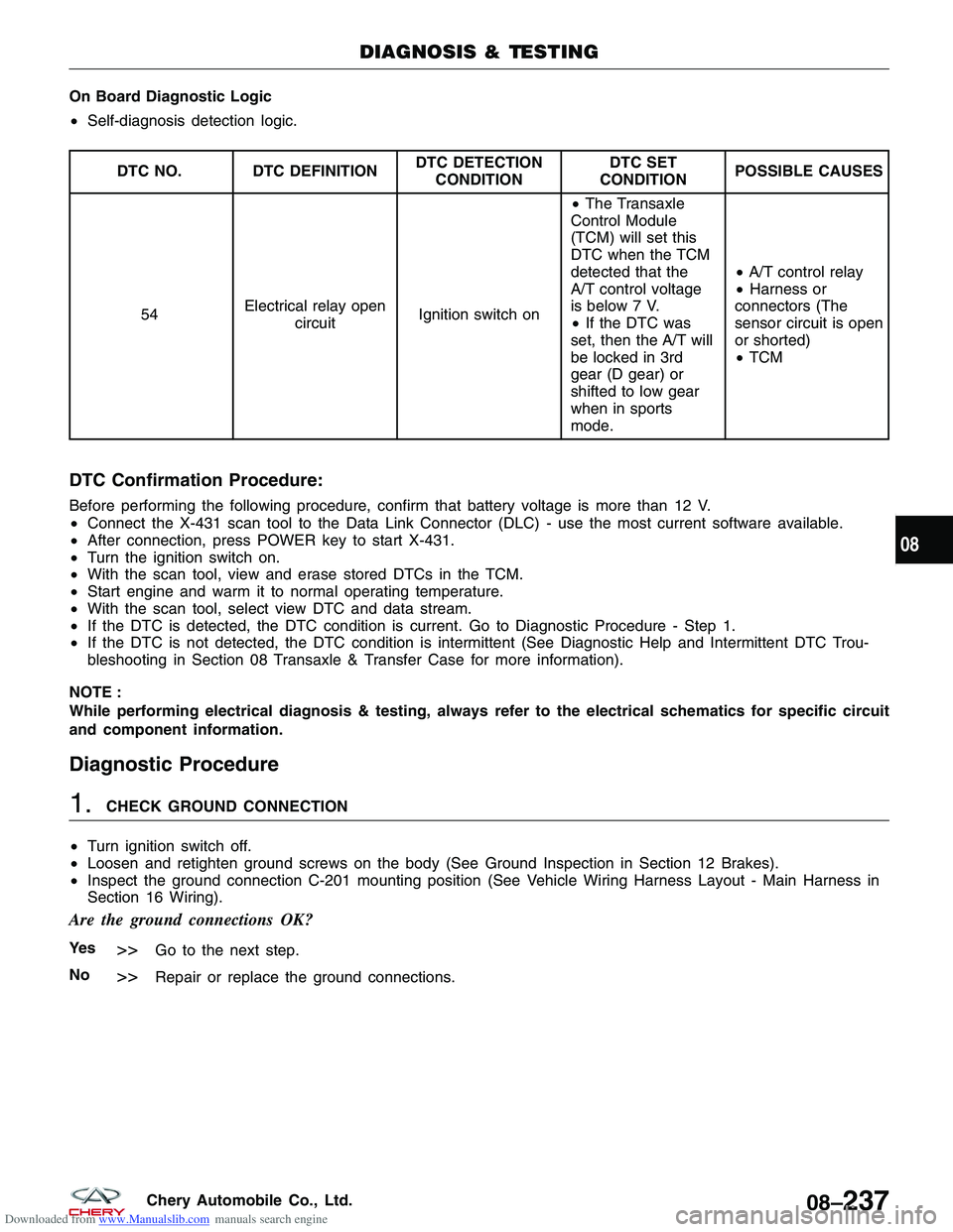
Downloaded from www.Manualslib.com manuals search engine On Board Diagnostic Logic
•Self-diagnosis detection logic.
DTC NO. DTC DEFINITION DTC DETECTION
CONDITION DTC SET
CONDITION POSSIBLE CAUSES
54 Electrical relay open
circuit Ignition switch on •
The Transaxle
Control Module
(TCM) will set this
DTC when the TCM
detected that the
A/T control voltage
is below 7 V.
• If the DTC was
set, then the A/T will
be locked in 3rd
gear (D gear) or
shifted to low gear
when in sports
mode. •
A/T control relay
• Harness or
connectors (The
sensor circuit is open
or shorted)
• TCM
DTC Confirmation Procedure:
Before performing the following procedure, confirm that battery voltage is more than 12 V.
• Connect the X-431 scan tool to the Data Link Connector (DLC) - use the most current software available.
• After connection, press POWER key to start X-431.
• Turn the ignition switch on.
• With the scan tool, view and erase stored DTCs in the TCM.
• Start engine and warm it to normal operating temperature.
• With the scan tool, select view DTC and data stream.
• If the DTC is detected, the DTC condition is current. Go to Diagnostic Procedure - Step 1.
• If the DTC is not detected, the DTC condition is intermittent (See Diagnostic Help and Intermittent DTC Trou-
bleshooting in Section 08 Transaxle & Transfer Case for more information).
NOTE :
While performing electrical diagnosis & testing, always refer to the electrical schematics for specific circuit
and component information.
Diagnostic Procedure
1.CHECK GROUND CONNECTION
• Turn ignition switch off.
• Loosen and retighten ground screws on the body (See Ground Inspection in Section 12 Brakes).
• Inspect the ground connection C-201 mounting position (See Vehicle Wiring Harness Layout - Main Harness in
Section 16 Wiring).
Are the ground connections OK?
Ye s>>Go to the next step.
No
>>Repair or replace the ground connections.
DIAGNOSIS & TESTING
08
08–237Chery Automobile Co., Ltd.
Page 1181 of 1903
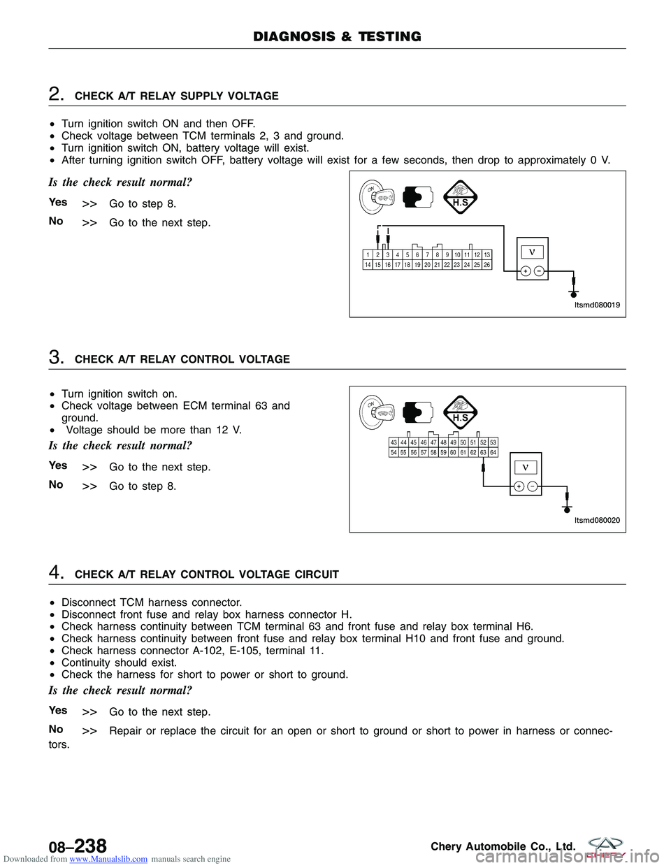
Downloaded from www.Manualslib.com manuals search engine 2.CHECK A/T RELAY SUPPLY VOLTAGE
• Turn ignition switch ON and then OFF.
• Check voltage between TCM terminals 2, 3 and ground.
• Turn ignition switch ON, battery voltage will exist.
• After turning ignition switch OFF, battery voltage will exist for a few seconds, then drop to approximately 0 V.
Is the check result normal?
Ye s>>Go to step 8.
No
>>Go to the next step.
3.CHECK A/T RELAY CONTROL VOLTAGE
• Turn ignition switch on.
• Check voltage between ECM terminal 63 and
ground.
• Voltage should be more than 12 V.
Is the check result normal?
Ye s>>Go to the next step.
No
>>Go to step 8.
4.CHECK A/T RELAY CONTROL VOLTAGE CIRCUIT
• Disconnect TCM harness connector.
• Disconnect front fuse and relay box harness connector H.
• Check harness continuity between TCM terminal 63 and front fuse and relay box terminal H6.
• Check harness continuity between front fuse and relay box terminal H10 and front fuse and ground.
• Check harness connector A-102, E-105, terminal 11.
• Continuity should exist.
• Check the harness for short to power or short to ground.
Is the check result normal?
Ye s>>Go to the next step.
No
>>Repair or replace the circuit for an open or short to ground or short to power in harness or connec-
tors.
DIAGNOSIS & TESTING
LTSMD080019
LTSMD080020
08–238Chery Automobile Co., Ltd.
Page 1182 of 1903
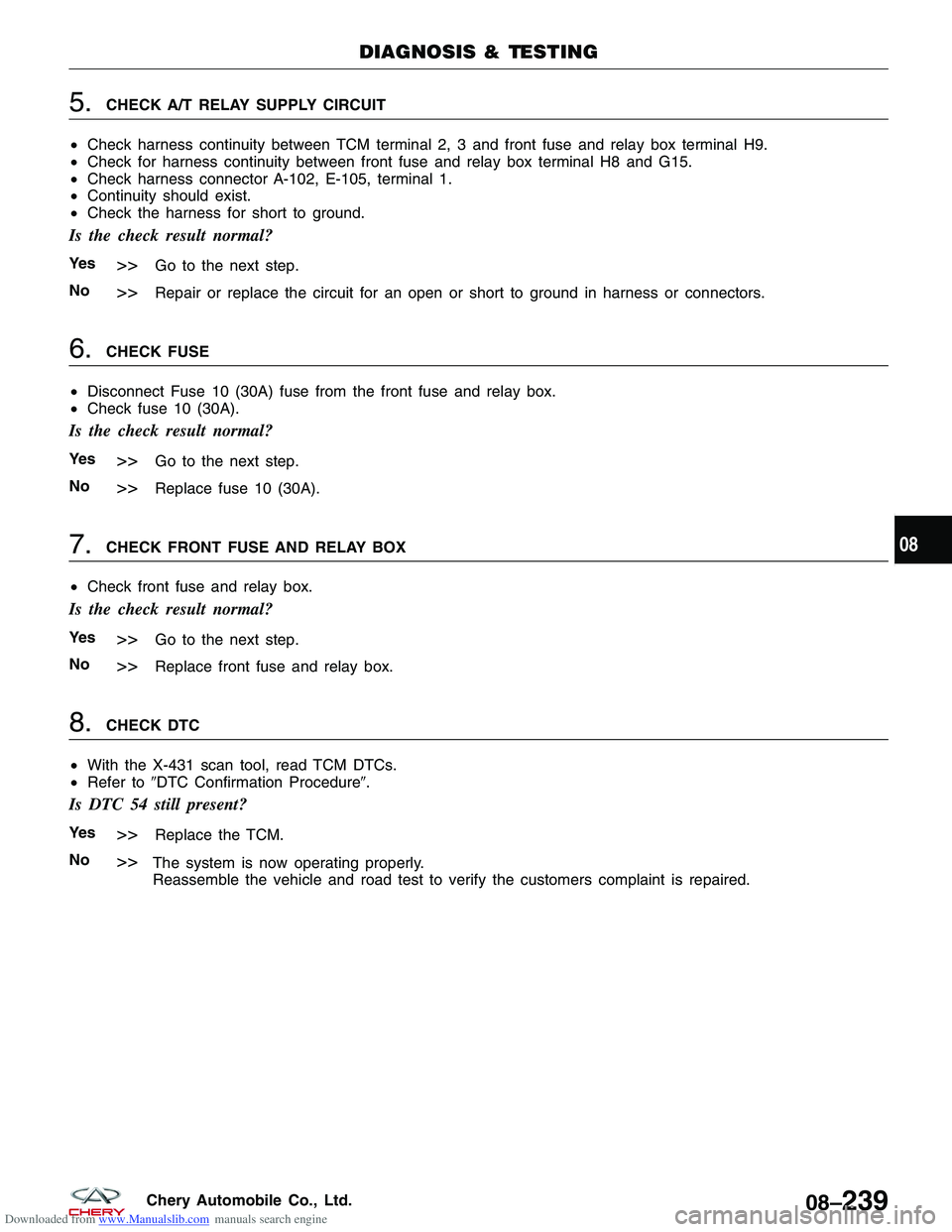
Downloaded from www.Manualslib.com manuals search engine 5.CHECK A/T RELAY SUPPLY CIRCUIT
• Check harness continuity between TCM terminal 2, 3 and front fuse and relay box terminal H9.
• Check for harness continuity between front fuse and relay box terminal H8 and G15.
• Check harness connector A-102, E-105, terminal 1.
• Continuity should exist.
• Check the harness for short to ground.
Is the check result normal?
Ye s>>Go to the next step.
No
>>Repair or replace the circuit for an open or short to ground in harness or connectors.
6.CHECK FUSE
• Disconnect Fuse 10 (30A) fuse from the front fuse and relay box.
• Check fuse 10 (30A).
Is the check result normal?
Ye s>>Go to the next step.
No
>>Replace fuse 10 (30A).
7.CHECK FRONT FUSE AND RELAY BOX
• Check front fuse and relay box.
Is the check result normal?
Ye s>>Go to the next step.
No
>>Replace front fuse and relay box.
8.CHECK DTC
• With the X-431 scan tool, read TCM DTCs.
• Refer to �DTC Confirmation Procedure�.
Is DTC 54 still present?
Ye s>>Replace the TCM.
No
>>The system is now operating properly.
Reassemble the vehicle and road test to verify the customers complaint is repaired.
DIAGNOSIS & TESTING
08
08–239Chery Automobile Co., Ltd.
Page 1183 of 1903
Downloaded from www.Manualslib.com manuals search engine ON-VEHICLE SERVICE
F4A4 Automatic Transaxle Assembly
Removal & Installation
1. Raise and support the vehicle.
2. Disconnect the negative battery cable.
3. Remove the battery and battery tray (See Battery Removal & Installation in Section 05 Starting & Charging).
4. Remove the air cleaner and air duct assembly.
5. Drain the cooling system (See Cooling System Draining Procedure in Section 06 Cooling System).
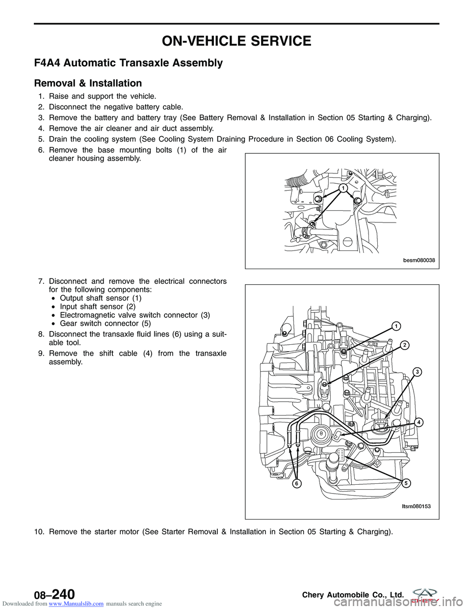
6. Remove the base mounting bolts (1) of the aircleaner housing assembly.
7. Disconnect and remove the electrical connectors for the following components:• Output shaft sensor (1)
• Input shaft sensor (2)
• Electromagnetic valve switch connector (3)
• Gear switch connector (5)
8. Disconnect the transaxle fluid lines (6) using a suit- able tool.
9. Remove the shift cable (4) from the transaxle assembly.
10. Remove the starter motor (See Starter Removal & Installation in Section 05 Starting & Charging).
BESM080038
LTSM080153
08–240Chery Automobile Co., Ltd.
Page 1184 of 1903
Downloaded from www.Manualslib.com manuals search engine 11. Remove the bolts (1) attaching the drive plate tothe torque converter.
(Tighten: Drive plate bolts to 75 N·m)
12. Support the engine using an engine support fixture or suitable jack.
13. Remove the engine to transaxle upper bolts and remove the bracket. (Tighten: Engine to transaxle upper bolts to 80 N·m)
14. Remove transaxle mount nuts (2) and the transaxle mount bracket bolts (1).
(Tighten: Transaxle mount nuts to 120 N·m)
15. Raise the vehicle.
16. Remove the drain plug (1) and drain the transaxle fluid.
ON-VEHICLE SERVICE
BESM080058
LTSM020156
LTSM080190
08
08–241Chery Automobile Co., Ltd.