2009 CHERY TIGGO coolant
[x] Cancel search: coolantPage 1079 of 1903
Downloaded from www.Manualslib.com manuals search engine ON-VEHICLE SERVICE
DPO Automatic Transaxle Assembly
Removal & Installation
1. Raise and support the vehicle.
2. Remove the engine cover.
3. Remove the battery and battery tray (See Battery Removal & Installation in Section 05 Starting & Charging).
4. Remove the air cleaner and air duct assembly.
5. Drain the cooling system (See Cooling System Draining Procedure in Section 06 Cooling System).
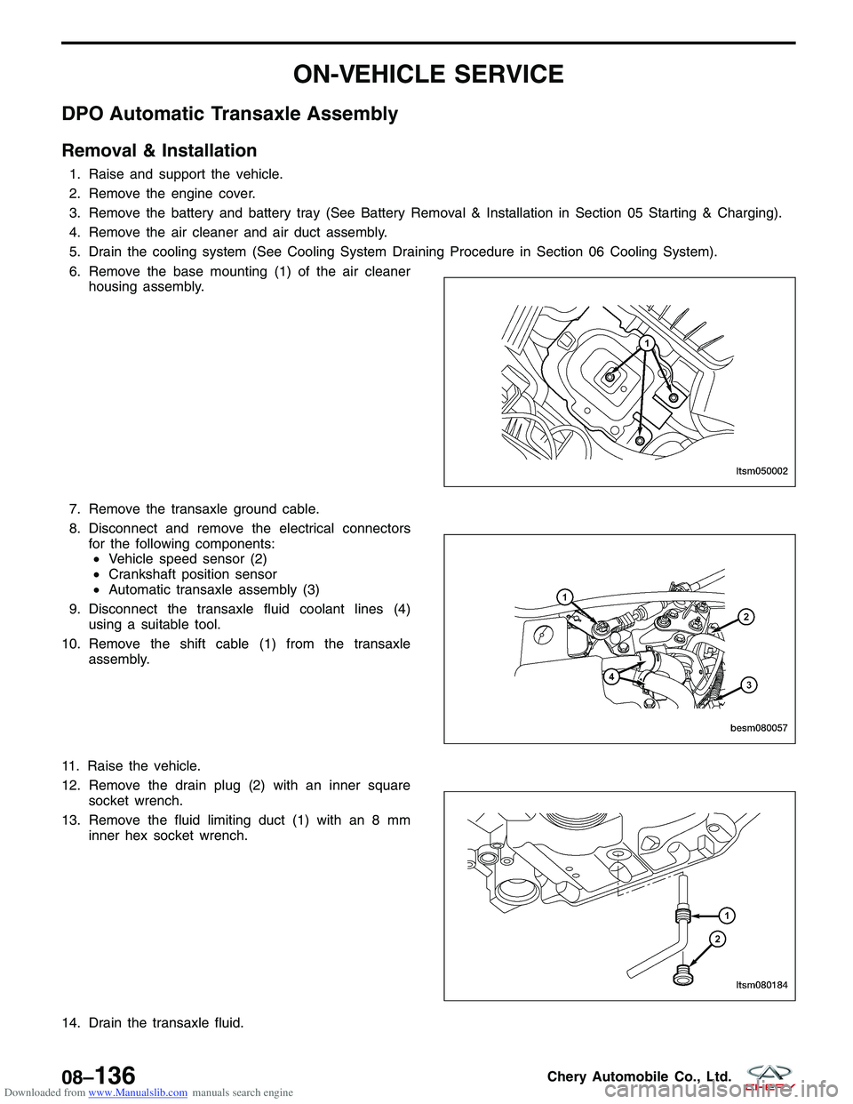
6. Remove the base mounting (1) of the air cleanerhousing assembly.
7. Remove the transaxle ground cable.
8. Disconnect and remove the electrical connectors for the following components:• Vehicle speed sensor (2)
• Crankshaft position sensor
• Automatic transaxle assembly (3)
9. Disconnect the transaxle fluid coolant lines (4) using a suitable tool.
10. Remove the shift cable (1) from the transaxle assembly.
11. Raise the vehicle.
12. Remove the drain plug (2) with an inner square socket wrench.
13. Remove the fluid limiting duct (1) with an 8 mm inner hex socket wrench.
14. Drain the transaxle fluid.
LTSM050002
BESM080057 LTSM080184
08–136Chery Automobile Co., Ltd.
Page 1496 of 1903
Downloaded from www.Manualslib.com manuals search engine Heater Performance
Engine coolant is delivered to the heater core through heater hoses. With the engine idling at normal operating tem-
perature, set the temperature control knob in the full hot position, the mode control switch knob in the floor heat
position, and the blower motor switch knob in the highest speed position. Using a test thermometer, check the tem-
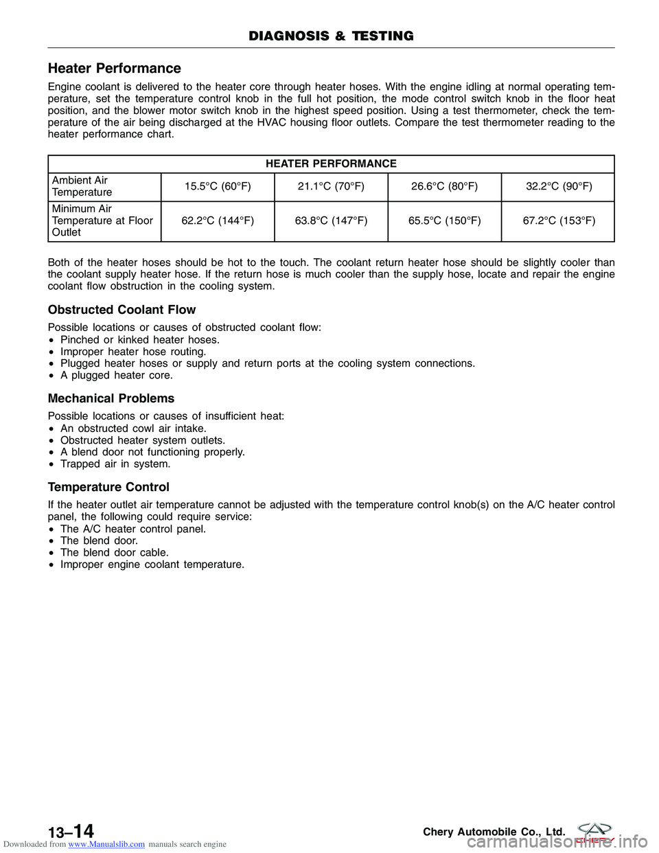
perature of the air being discharged at the HVAC housing floor outlets. Compare the test thermometer reading to the
heater performance chart.
HEATER PERFORMANCE
Ambient Air
Temperature 15.5°C (60°F) 21.1°C (70°F) 26.6°C (80°F) 32.2°C (90°F)
Minimum Air
Temperature at Floor
Outlet 62.2°C (144°F) 63.8°C (147°F) 65.5°C (150°F) 67.2°C (153°F)
Both of the heater hoses should be hot to the touch. The coolant return heater hose should be slightly cooler than
the coolant supply heater hose. If the return hose is much cooler than the supply hose, locate and repair the engine
coolant flow obstruction in the cooling system.
Obstructed Coolant Flow
Possible locations or causes of obstructed coolant flow:
• Pinched or kinked heater hoses.
• Improper heater hose routing.
• Plugged heater hoses or supply and return ports at the cooling system connections.
• A plugged heater core.
Mechanical Problems
Possible locations or causes of insufficient heat:
•An obstructed cowl air intake.
• Obstructed heater system outlets.
• A blend door not functioning properly.
• Trapped air in system.
Temperature Control
If the heater outlet air temperature cannot be adjusted with the temperature control knob(s) on the A/C heater control
panel, the following could require service:
•The A/C heater control panel.
• The blend door.
• The blend door cable.
• Improper engine coolant temperature.
DIAGNOSIS & TESTING
13–14Chery Automobile Co., Ltd.
Page 1517 of 1903
Downloaded from www.Manualslib.com manuals search engine DIAGNOSIS & TESTING
Mechanical Problems
Possible locations or causes of insufficient heat:
•An obstructed cowl air intake.
• Obstructed heater system outlets.
• A blend door not functioning properly.
• Trapped air in system.
Temperature Control
If the heater outlet air temperature cannot be adjusted with the temperature control knob(s) on the A/C heater control
panel, the following could require service:
•The A/C heater control.
• The blend door actuator(s).
• The wire harness circuits for the A/C heater control or the blend door actuator(s).
• The blend door(s).
• Improper engine coolant temperature.
A/C Compressor Noise Testing
When investigating an A/C system related noise, you must first know the conditions under which the noise occurs.
These conditions include: weather, vehicle speed, transaxle in gear or neutral, engine speed, engine temperature,
and any other special conditions. Noises that develop during A/C operation can often be misleading. For example:
what sounds like a failed bearing, may be caused by loose bolts, nuts, mounting brackets or a loose compressor
assembly.
NOTE :
The A/C compressor must be replaced if any unusual noise is heard from the compressor itself.
NOTE :
Drive belts are speed sensitive. At different engine speeds and depending upon drive belt tension, drive belts can
develop noises that are mistaken for an A/C compressor noise. Improper drive belt tension can cause a misleading
noise when the compressor is operating at maximum displacement, which may not occur when the compressor is at
minimum displacement.
1. Select a quiet area for testing.
2. Duplicate the complaint conditions as much as possible.
3. Turn the A/C system On and Off several times to clearly identify any compressor noise.
4. Listen to the A/C compressor while it is operating at maximum and minimum displacement.
5. Probe the A/C compressor with an engine stethoscope or a long screwdriver with the handle held to your ear to better localize the source of the noise.
6. To duplicate high-ambient temperature conditions (high head pressure), restrict the air flow through the A/C con- denser. Install a manifold gauge set or a scan tool to ensure that the discharge pressure does not exceed 2600
kPa.
7. Check the condition of the accessory drive belt. NOTE: The A/C compressor must be replaced if the drive hub is broken or if the compressor shaft does not
rotate smoothly.
8. Check the compressor hub and pulley and bearing assembly. Ensure that the hub and pulley are properly aligned and that the pulley bearing is mounted securely to the A/C compressor.
9. Check the refrigerant system plumbing for incorrect routing, rubbing or interference, which can cause unusual noises. Also check the refrigerant lines and hoses for kinks or sharp bends that will restrict refrigerant flow, which
can cause noises.
10. Loosen all of the compressor mounting hardware and retighten. CAUTION: Do not run the engine with a vacuum pump in operation or with a vacuum present within the
A/C system. Failure to follow this caution will result in serious A/C compressor damage.
11. If the noise is from opening and closing the high pressure relief valve, recover, evacuate and recharge the refrig- erant system. If the high pressure relief valve still does not seat properly, replace the A/C compressor.
13
13–35Chery Automobile Co., Ltd.
Page 1529 of 1903
Downloaded from www.Manualslib.com manuals search engine Heater Core
Description
The heater core is located in the HVAC housing. The heater core is a heat exchanger made of rows of tubes with
fins and is positioned within the air distribution housing so that only the selected amount of air entering the housing
passes through the heater core before it is distributed through the heating-A/C system ducts and outlets. One end of
the heater core is fitted with a tank that includes the fittings for the heater core tubes. The heater core can only be
serviced by removing the HVAC housing from the vehicle.
Operation
Engine coolant is circulated through the heater hoses to the heater core at all times. As the coolant flows through the
heater core, heat is removed from the engine and is transferred to the heater core tubes and fins. Air directed
through the heater core picks up the heat from the heater core fins. The blend-air door allows control of the heater
output air temperature by regulating the amount of air flowing through the heater core. The blower motor speed con-
trols the volume of air flowing through the HVAC housing.
Removal & Installation
1. Drain the cooling system (See Cooling System Draining Procedure in Section 06 Cooling System).
2. Evacuate the A/C system (See A/C System Evacuation and Recharge in Section 13 Heating & Air Conditioning).
3. Remove the HVAC housing assembly and place it on a workbench (See HVAC Housing Removal & Installationin Section 13 Heating & Air Conditioning).
4. Remove the retaining bolts and clamps.
5. Remove the heater core.
6. Installation is in the reverse order of removal.
Installation Notes:
• Verify the cooling system is filled to proper specifications.
ON-VEHICLE SERVICE
13
13–47Chery Automobile Co., Ltd.
Page 1636 of 1903
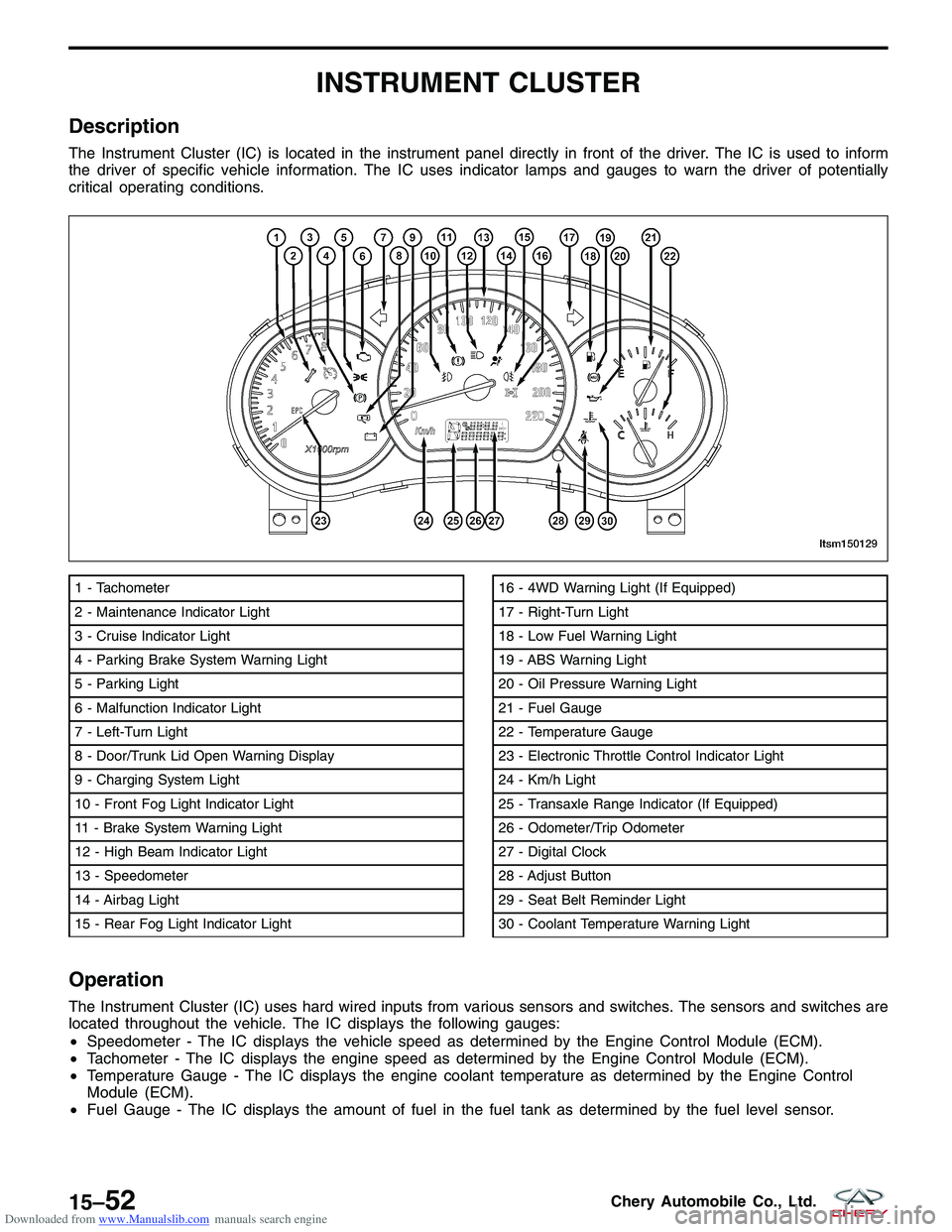
Downloaded from www.Manualslib.com manuals search engine INSTRUMENT CLUSTER
Description
The Instrument Cluster (IC) is located in the instrument panel directly in front of the driver. The IC is used to inform
the driver of specific vehicle information. The IC uses indicator lamps and gauges to warn the driver of potentially
critical operating conditions.
Operation
The Instrument Cluster (IC) uses hard wired inputs from various sensors and switches. The sensors and switches are
located throughout the vehicle. The IC displays the following gauges:
•Speedometer - The IC displays the vehicle speed as determined by the Engine Control Module (ECM).
• Tachometer - The IC displays the engine speed as determined by the Engine Control Module (ECM).
• Temperature Gauge - The IC displays the engine coolant temperature as determined by the Engine Control
Module (ECM).
• Fuel Gauge - The IC displays the amount of fuel in the fuel tank as determined by the fuel level sensor.
1 - Tachometer
2 - Maintenance Indicator Light
3 - Cruise Indicator Light
4 - Parking Brake System Warning Light
5 - Parking Light
6 - Malfunction Indicator Light
7 - Left-Turn Light
8 - Door/Trunk Lid Open Warning Display
9 - Charging System Light
10 - Front Fog Light Indicator Light
11 - Brake System Warning Light
12 - High Beam Indicator Light
13 - Speedometer
14 - Airbag Light
15 - Rear Fog Light Indicator Light16 - 4WD Warning Light (If Equipped)
17 - Right-Turn Light
18 - Low Fuel Warning Light
19 - ABS Warning Light
20 - Oil Pressure Warning Light
21 - Fuel Gauge
22 - Temperature Gauge
23 - Electronic Throttle Control Indicator Light
24 - Km/h Light
25 - Transaxle Range Indicator (If Equipped)
26 - Odometer/Trip Odometer
27 - Digital Clock
28 - Adjust Button
29 - Seat Belt Reminder Light
30 - Coolant Temperature Warning Light
LTSM150129
15–52Chery Automobile Co., Ltd.
Page 1646 of 1903
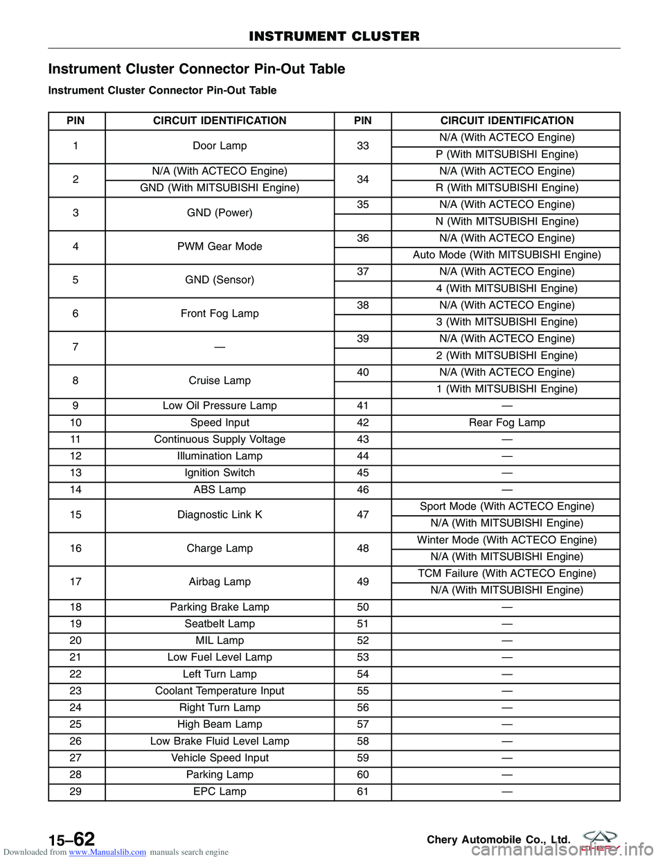
Downloaded from www.Manualslib.com manuals search engine Instrument Cluster Connector Pin-Out Table
Instrument Cluster Connector Pin-Out Table
PINCIRCUIT IDENTIFICATION PINCIRCUIT IDENTIFICATION
1 Door Lamp 33N/A (With ACTECO Engine)
P (With MITSUBISHI Engine)
2 N/A (With ACTECO Engine)
34N/A (With ACTECO Engine)
GND (With MITSUBISHI Engine) R (With MITSUBISHI Engine)
3 GND (Power) 35
N/A (With ACTECO Engine)
N (With MITSUBISHI Engine)
4 PWM Gear Mode 36
N/A (With ACTECO Engine)
Auto Mode (With MITSUBISHI Engine)
5 GND (Sensor) 37
N/A (With ACTECO Engine)
4 (With MITSUBISHI Engine)
6 Front Fog Lamp 38
N/A (With ACTECO Engine)
3 (With MITSUBISHI Engine)
7— 39
N/A (With ACTECO Engine)
2 (With MITSUBISHI Engine)
8 Cruise Lamp 40
N/A (With ACTECO Engine)
1 (With MITSUBISHI Engine)
9 Low Oil Pressure Lamp 41—
10 Speed Input 42Rear Fog Lamp
11 Continuous Supply Voltage 43—
12 Illumination Lamp 44—
13 Ignition Switch 45—
14 ABS Lamp 46—
15 Diagnostic Link K 47Sport Mode (With ACTECO Engine)
N/A (With MITSUBISHI Engine)
16 Charge Lamp 48Winter Mode (With ACTECO Engine)
N/A (With MITSUBISHI Engine)
17 Airbag Lamp 49TCM Failure (With ACTECO Engine)
N/A (With MITSUBISHI Engine)
18 Parking Brake Lamp 50—
19 Seatbelt Lamp 51—
20 MIL Lamp 52—
21 Low Fuel Level Lamp 53—
22 Left Turn Lamp 54—
23 Coolant Temperature Input 55—
24 Right Turn Lamp 56—
25 High Beam Lamp 57—
26 Low Brake Fluid Level Lamp 58—
27 Vehicle Speed Input 59—
28 Parking Lamp 60—
29 EPC Lamp 61—
INSTRUMENT CLUSTER
15–62Chery Automobile Co., Ltd.
Page 1657 of 1903
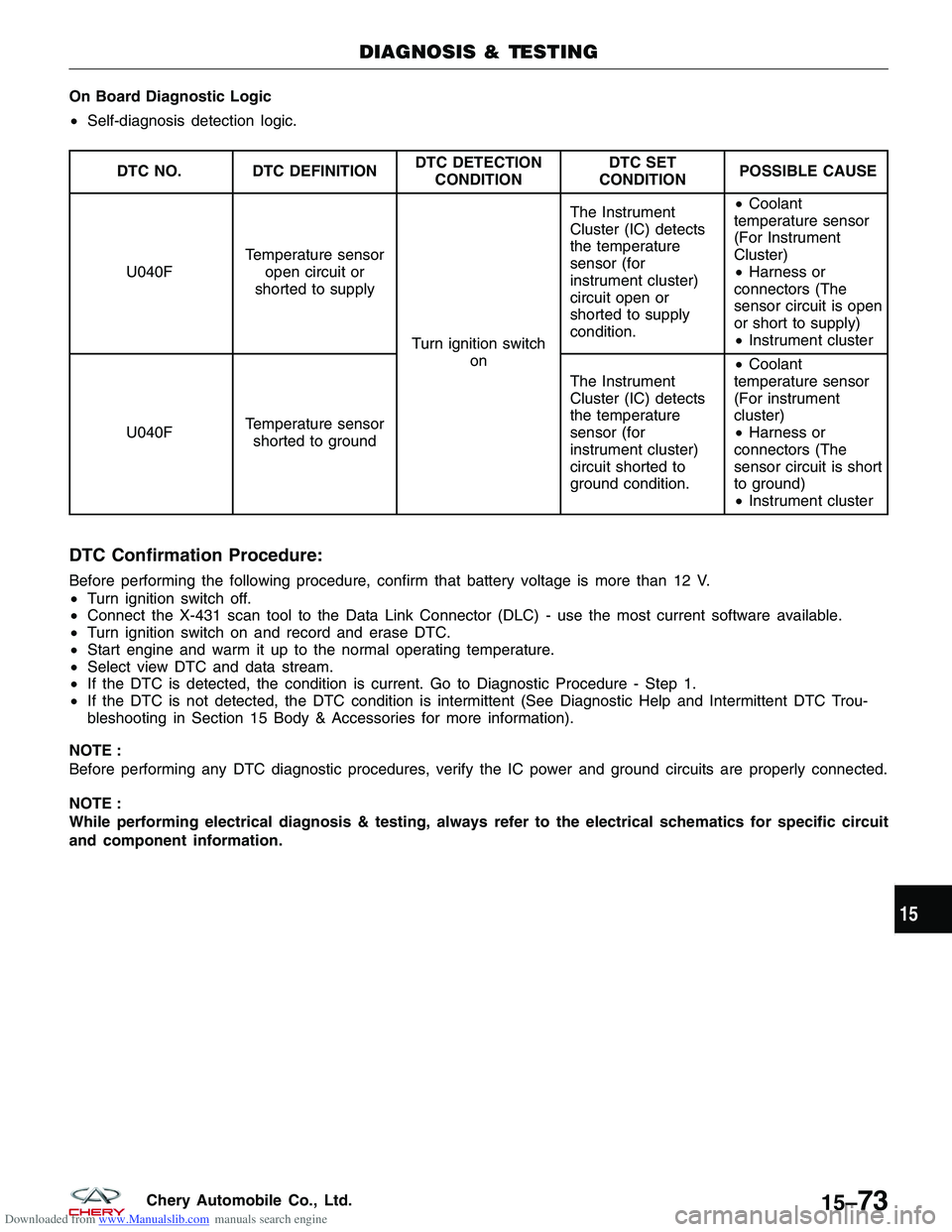
Downloaded from www.Manualslib.com manuals search engine On Board Diagnostic Logic
•Self-diagnosis detection logic.
DTC NO. DTC DEFINITION DTC DETECTION
CONDITION DTC SET
CONDITION POSSIBLE CAUSE
U040F Temperature sensor
open circuit or
shorted to supply
Turn ignition switchon The Instrument
Cluster (IC) detects
the temperature
sensor (for
instrument cluster)
circuit open or
shorted to supply
condition.
•
Coolant
temperature sensor
(For Instrument
Cluster)
• Harness or
connectors (The
sensor circuit is open
or short to supply)
• Instrument cluster
U040F Temperature sensor
shorted to ground The Instrument
Cluster (IC) detects
the temperature
sensor (for
instrument cluster)
circuit shorted to
ground condition.•
Coolant
temperature sensor
(For instrument
cluster)
• Harness or
connectors (The
sensor circuit is short
to ground)
• Instrument cluster
DTC Confirmation Procedure:
Before performing the following procedure, confirm that battery voltage is more than 12 V.
• Turn ignition switch off.
• Connect the X-431 scan tool to the Data Link Connector (DLC) - use the most current software available.
• Turn ignition switch on and record and erase DTC.
• Start engine and warm it up to the normal operating temperature.
• Select view DTC and data stream.
• If the DTC is detected, the condition is current. Go to Diagnostic Procedure - Step 1.
• If the DTC is not detected, the DTC condition is intermittent (See Diagnostic Help and Intermittent DTC Trou-
bleshooting in Section 15 Body & Accessories for more information).
NOTE :
Before performing any DTC diagnostic procedures, verify the IC power and ground circuits are properly connected.
NOTE :
While performing electrical diagnosis & testing, always refer to the electrical schematics for specific circuit
and component information.
DIAGNOSIS & TESTING
15
15–73Chery Automobile Co., Ltd.
Page 1658 of 1903
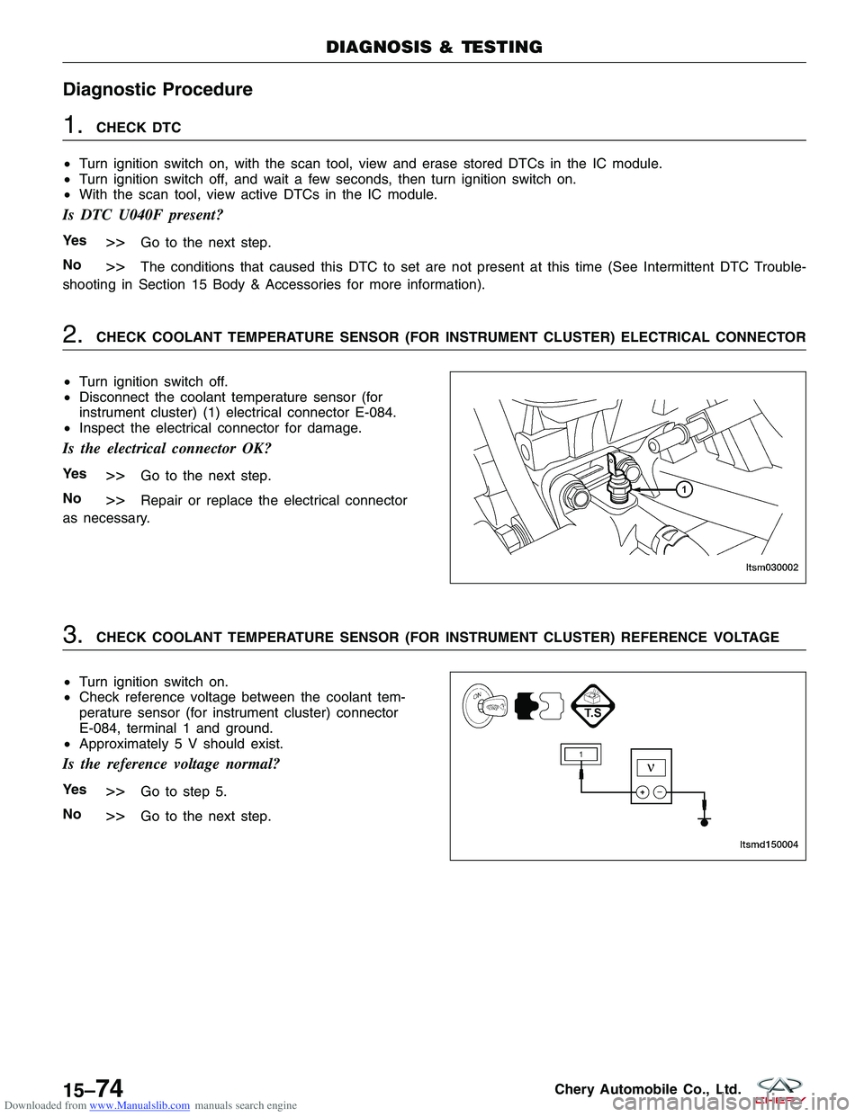
Downloaded from www.Manualslib.com manuals search engine Diagnostic Procedure
1.CHECK DTC
• Turn ignition switch on, with the scan tool, view and erase stored DTCs in the IC module.
• Turn ignition switch off, and wait a few seconds, then turn ignition switch on.
• With the scan tool, view active DTCs in the IC module.
Is DTC U040F present?
Ye s>>Go to the next step.
No
>>The conditions that caused this DTC to set are not present at this time (See Intermittent DTC Trouble-
shooting in Section 15 Body & Accessories for more information).
2.CHECK COOLANT TEMPERATURE SENSOR (FOR INSTRUMENT CLUSTER) ELECTRICAL CONNECTOR
• Turn ignition switch off.
• Disconnect the coolant temperature sensor (for
instrument cluster) (1) electrical connector E-084.
• Inspect the electrical connector for damage.
Is the electrical connector OK?
Ye s>>Go to the next step.
No
>>Repair or replace the electrical connector
as necessary.
3.CHECK COOLANT TEMPERATURE SENSOR (FOR INSTRUMENT CLUSTER) REFERENCE VOLTAGE
• Turn ignition switch on.
• Check reference voltage between the coolant tem-
perature sensor (for instrument cluster) connector
E-084, terminal 1 and ground.
• Approximately 5 V should exist.
Is the reference voltage normal?
Ye s>>Go to step 5.
No
>>Go to the next step.
DIAGNOSIS & TESTING
LTSM030002
LTSMD150004
15–74Chery Automobile Co., Ltd.