2009 BMW Z4 SDRIVE30I navigation system
[x] Cancel search: navigation systemPage 77 of 248

Controls
75Reference
At a glance
Driving tips
Communications
Navigation
Entertainment
Mobility
3."Limit:"
4. Turn the controller until the desired limit is
displayed.
5. Press the controller.
The speed limit is stored.
Applying your current speed as
the limit
1. "Settings"
2. "Limit"
3. "Select current speed"
4. Press the controller.
The system adopts your current speed as the
limit.
Activating/deactivating the limit
1. "Settings"
2. "Limit"
3. "Limit warning"
4. Press the controller.
The limit warning is switched on.
Settings on the Control
Display
Language on the Control Display
Setting the language
iDrive, for operating pr inciple refer to page16.
1. "Settings"
2. "Language/Units"
3. "Language:"
4. Select the desired language.
The setting is stored for the remote control cur-
rently in use.
Setting the voice dialog
Switch between a standard dialog and a short
dialog.
1. "Settings"
2. "Language/Units"
3. "Speech mode:"
4. Select the desired dialog.
The setting is stored for the remote control cur-
rently in use.
Page 79 of 248
Controls
77Reference
At a glance
Driving tips
Communications
Navigation
Entertainment
Mobility
Technology for driving comfort and safety
Park Distance Control PDC*
The concept
The PDC assists you with maneuvering in tight
parking spaces. Acoustic signals and a visual
indicator
warn you of the presence of an object
in front of
* or behind your ve hicle. To measure
the distance, there are four ultrasonic sensors
in either bumper.
These sensors have a range of approx. 6.5 ft/
2 m. However, an acoustic warning does not
sound until an object is approx. 24 in/60 cm
from the corner sensors, or approx. 5 ft/1.50 m
from the center sensors.
PDC is a parking aid that can indicate
objects when they are approached
slowly, as is usually th e case when parking.
Avoid approaching an obje ct a t h i g h s p e e d , o t h -
erwise physical circumstances may lead to the
system warning being issued too late. <
Switching on automatically
With the engine running or the ignition switched
on, the system is activated after approx. 1 sec-
ond when you engage reverse gear or move the
automatic transmission selector lever to
position R. Wait this short period before driving.
Switching off automatically
After approx. 165 ft/50 m of driving or above
approx. 20 mph or 30 km/h, the system
switches off and the LED goes out.
Signal tones
When nearing an object, its position is indicated
correspondingly by an in terval tone. As the dis-
tance between vehicle and object decreases,
the intervals between the tones become
shorter. If the distance to the nearest object
falls to below roughly 1 f t/30 cm, then a contin-
uous tone sounds.
An interval tone is interrupted after approx.
3seconds >
if you remain in front of an object that has
been detected by only one of the corner
sensors
> if you are driving parallel to a wall.
Malfunction
The indicator lamp in the instrument
cluster comes on. PDC is malfunc-
tioning. A message appears on the
Control Display. Have the system checked.
To avoid this problem, keep the sensors clean
and free of ice or snow in order to ensure that
they will continue to operate effectively. When
using a high-pressure cleaner, do not spray the
sensors for extended periods of time and only
from a distance of at least 4 in/10 cm.
PDC with visual warning
The approach of the vehicle to an object is
shown on the Control Display. Objects that are
farther away are displayed on the Control Dis-
play before a signal to ne sounds. The display
appears on the Control Display as soon as PDC
is activated.
System limitations
Even with PDC, final responsibility for
estimating the distance between the
vehicle and any obstructions always remains
with the driver. Even when sensors are pro-
vided, there is a blind spot in which objects can
no longer be detected. The system is also sub-
ject to the physical limit s that apply to all forms
of ultrasonic measurement, such as those
encountered with trailer towbars and hitches,
thin or wedge-shaped objects, etc. Low objects
that have already been displayed, e.g. curbs,
can disappear again from the detection area of
the sensors before or af ter a continuous tone
sounds. Higher, protruding objects, e.g. ledges,
cannot be detected. Therefore, always drive
cautiously, otherwise there is a risk of personal
injury or property damage.
Page 81 of 248
Controls
79Reference
At a glance
Driving tips
Communications
Navigation
Entertainment
Mobility
Dynamic Driving Control
The concept
Dynamic Driving Control can be used to adjust
the driving dynamics of the vehicle.
Several programs are available for this purpose;
they can be activated using the two Dynamic
Driving Control buttons.
The following characteristics are adapted,
depending on which program was selected:
> Engine response.
> Shift times of the automatic transmission
*.
> Power steering support
*.
> Changes in the suspension characteristics
through damping control
*.
> Vehicle stabilization through DSC Dynamic
Stability Control.
Operating the programs
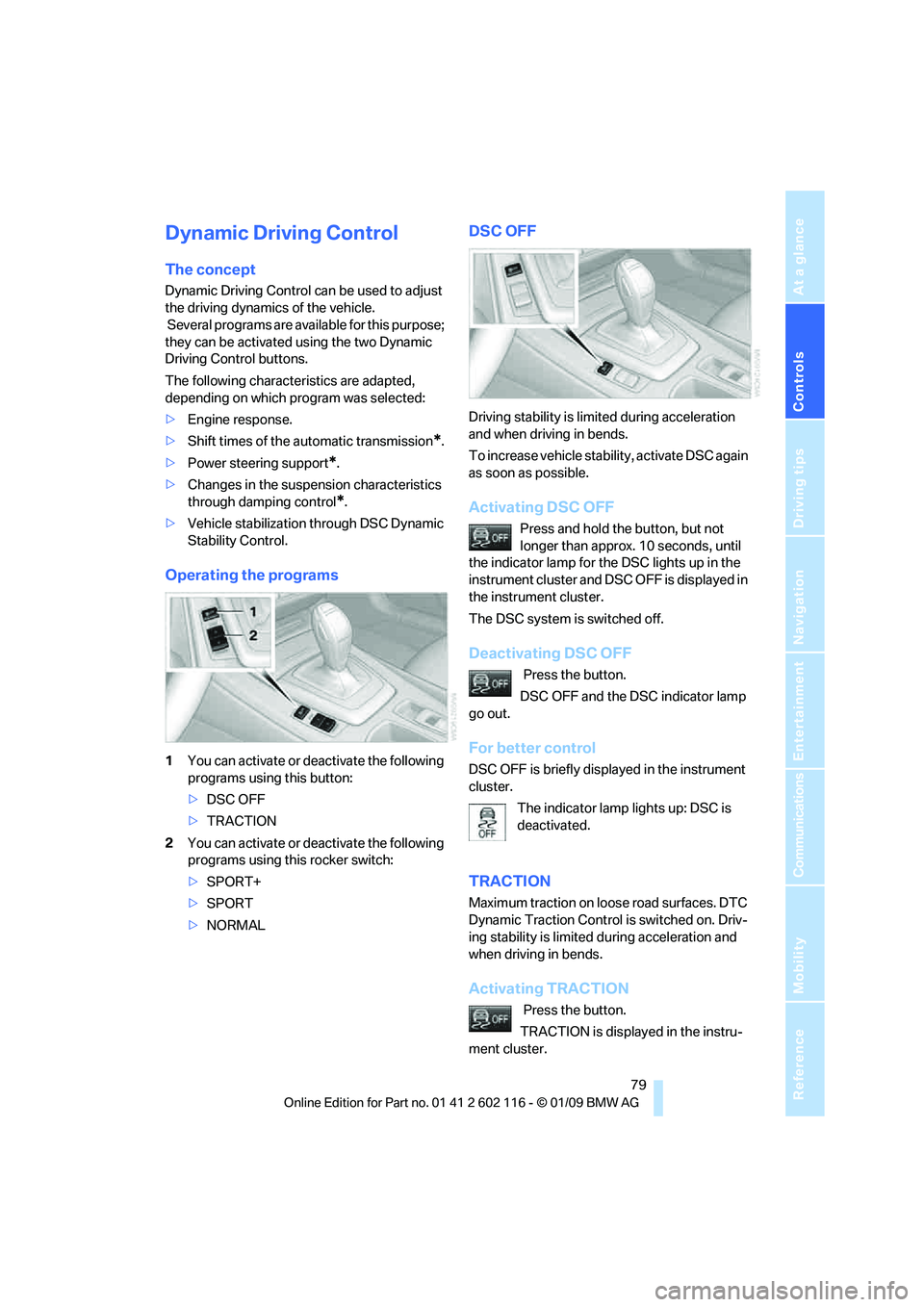
1You can activate or de activate the following
programs using this button:
> DSC OFF
> TRACTION
2 You can activate or de activate the following
programs using this rocker switch:
> SPORT+
> SPORT
> NORMAL
DSC OFF
Driving stability is limited during acceleration
and when driving in bends.
To increase vehicle stability, activate DSC again
as soon as possible.
Activating DSC OFF
Press and hold the button, but not
longer than approx. 10 seconds, until
the indicator lamp for the DSC lights up in the
instrument cluster and DSC OFF is displayed in
the instrument cluster.
The DSC system is switched off.
Deactivating DSC OFF
Press the button.
DSC OFF and the DSC indicator lamp
go out.
For better control
DSC OFF is briefly displayed in the instrument
cluster.
The indicator lamp lights up: DSC is
deactivated.
TRACTION
Maximum traction on loose road surfaces. DTC
Dynamic Traction Control is switched on. Driv-
ing stability is limited during acceleration and
when driving in bends.
Activating TRACTION
Press the button.
TRACTION is displayed in the instru-
ment cluster.
Page 83 of 248
Controls
81Reference
At a glance
Driving tips
Communications
Navigation
Entertainment
Mobility
Flat Tire Monitor FTM*
The concept
The Flat Tire Monitor detects pressure loss in a
tire by comparing the rotating speeds of the
individual tires while moving.
In the event of pressure loss, the rolling circum-
ference changes and, thus, the rotating speed
of the affected wheel. This change is detected
and is reported as a flat tire.
Functional requirement
In order to assure the reliable reporting of a flat
tire, the system must be initialized for the cor-
rect tire inflation pressure.The system must be reinitialized each
time a tire inflation pressure has been cor-
rected or a wheel or tire has been changed. <
System limitations
The Flat Tire Monitor is unable to warn
the driver of sudden, severe tire damage
caused by external factors, nor can it identify
the gradual loss of pressure that will inevitably
occur in all four tires over a lengthy period
of time. <
In the following situations, the system could be
delayed or malfunction:
> System has not been initialized
> Driving on snowy or slippery road surface
> Performance-oriented style of driving: slip
in the drive wheels, hi gh lateral acceleration
> Snow chains are attached
Initializing the system
The initialization is completed during driv-
ing, which can be interrupted at any time.
When driving resumes, the initialization is con-
tinued automatically.
Do not initialize the syst em while snow chains
are attached. <
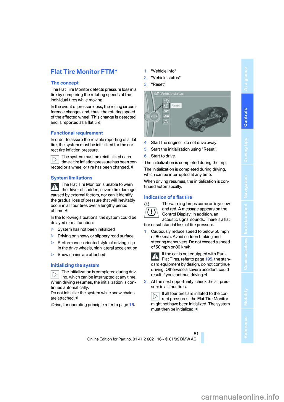
iDrive, for operating principle refer to page 16.1.
"Vehicle Info"
2. "Vehicle status"
3. "Reset"
4. Start the engine - do not drive away.
5. Start the initializat ion using "Reset".
6. Start to drive.
The initialization is completed during the trip.
The initialization is comp leted during driving,
which can be interrupted at any time.
When driving resumes, the initialization is con-
tinued automatically.
Indication of a flat tire
The warning lamps come on in yellow
and red. A message appears on the
Control Display. In addition, an
acoustic signal sounds. There is a flat
tire or substantial loss of tire pressure.
1. Cautiously reduce speed to below 50 mph
or 80 km/h. Avoid sudden braking and
steering maneuvers. Do not exceed a speed
of 50 mph or 80 km/h.
If the car is not equipped with Run-
Flat Tires, refer to page 195, the stan-
dard equipment by design, do not continue
driving. Otherwise a severe accident could
result if you continue driving. <
2. At the next opportunity, check the air pres-
sure in all four tires.
If all four tires are inflated to the cor-
rect pressures, the Flat Tire Monitor
might not have been initialized. The system
must then be initialized. <
Page 85 of 248
Controls
83Reference
At a glance
Driving tips
Communications
Navigation
Entertainment
Mobility
Green
The tire inflation pressure corresponds to the
established target value.
"TPM active" appears on the Control Display.
One wheel yellow
There is a flat tire or substantial loss of tire pres-
sure in the indicated tire. A message appears on
the Control Display.
All wheels yellow
There is a flat tire or su bstantial loss of tire pres-
sure in several tires. A message appears on the
Control Display.
Gray
The system cannot detect a puncture.
Possible reasons for this:
> TPM is being reset
> Temporary malfunction caused by systems
or devices using the same radio frequency
> Malfunction
Resetting the system
Each time a tire inflation pressure has
been corrected or a wheel or tire has been
changed, reset the system. <
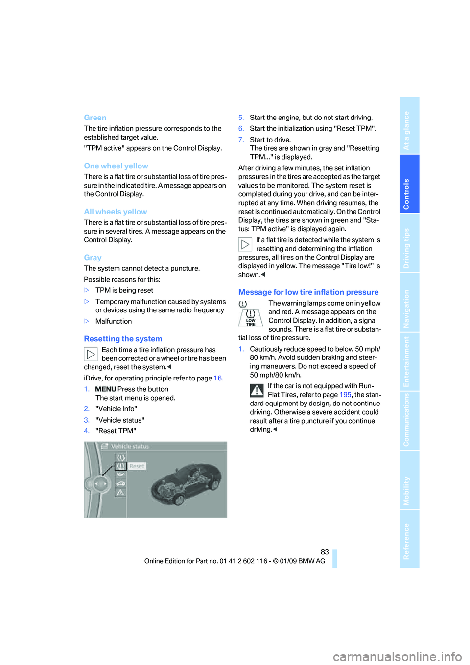
iDrive, for operating principle refer to page 16.
1. Press the button
The start menu is opened.
2. "Vehicle Info"
3. "Vehicle status"
4. "Reset TPM" 5.
Start the engine, but do not start driving.
6. Start the initializatio n using "Reset TPM".
7. Start to drive.
The tires are shown in gray and "Resetting
TPM..." is displayed.
After driving a few minutes, the set inflation
pressures in the tires are accepted as the target
values to be monitored. The system reset is
completed during your drive, and can be inter-
rupted at any time. When driving resumes, the
reset is continued automatically. On the Control
Display, the tires are shown in green and "Sta-
tus: TPM active" is displayed again. If a flat tire is detected while the system is
resetting and determining the inflation
pressures, all tires on the Control Display are
displayed in yellow. The message "Tire low!" is
shown. <
Message for low tire inflation pressure
The warning lamps come on in yellow
and red. A message appears on the
Control Display. In addition, a signal
sounds. There is a flat tire or substan-
tial loss of tire pressure.
1. Cautiously reduce speed to below 50 mph/
80 km/h. Avoid sudden braking and steer-
ing maneuvers. Do not exceed a speed of
50 mph/80 km/h.
If the car is not equipped with Run-
Flat Tires, refer to page 195, the stan-
dard equipment by design, do not continue
driving. Otherwise a severe accident could
result after a tire punc ture if you continue
driving. <
Page 87 of 248
Controls
85Reference
At a glance
Driving tips
Communications
Navigation
Entertainment
Mobility
The TPMS malfunction indicator is combined
with the low tire pressure telltale. When the sys-
tem detects a malfunction, the telltale will flash
for approximately one minute and then remain
continuously lit. This sequence will continue
upon subsequent vehicle startups as long as
the malfunction exists. When the malfunction
indicator is illuminated, the system may not be
able to detect or signal low tire pressure as
intended. TPMS malfunctions may occur for a
variety of reasons, including the installation of
replacement or alternate tires or wheels on the
vehicle that prevent the TPMS from functioning
properly. Always check the TPMS malfunction
telltale after replacing one or more tires or
wheels on your vehicle to ensure that the
replacement or alternate tires and wheels allow
the TPMS to continue to function properly.
Servotronic*
The concept
The Servotronic varies the steering force
required to turn the wh eels depending on the
speed at which you are driving. When you are
driving at low speeds, power steering provides
more support, i. e. little effort is needed to turn
the wheels. Power steering support lessens as
your speed increases.
The system works automatically.
Malfunction
Malfunctions are displayed via Check Control
Airbags
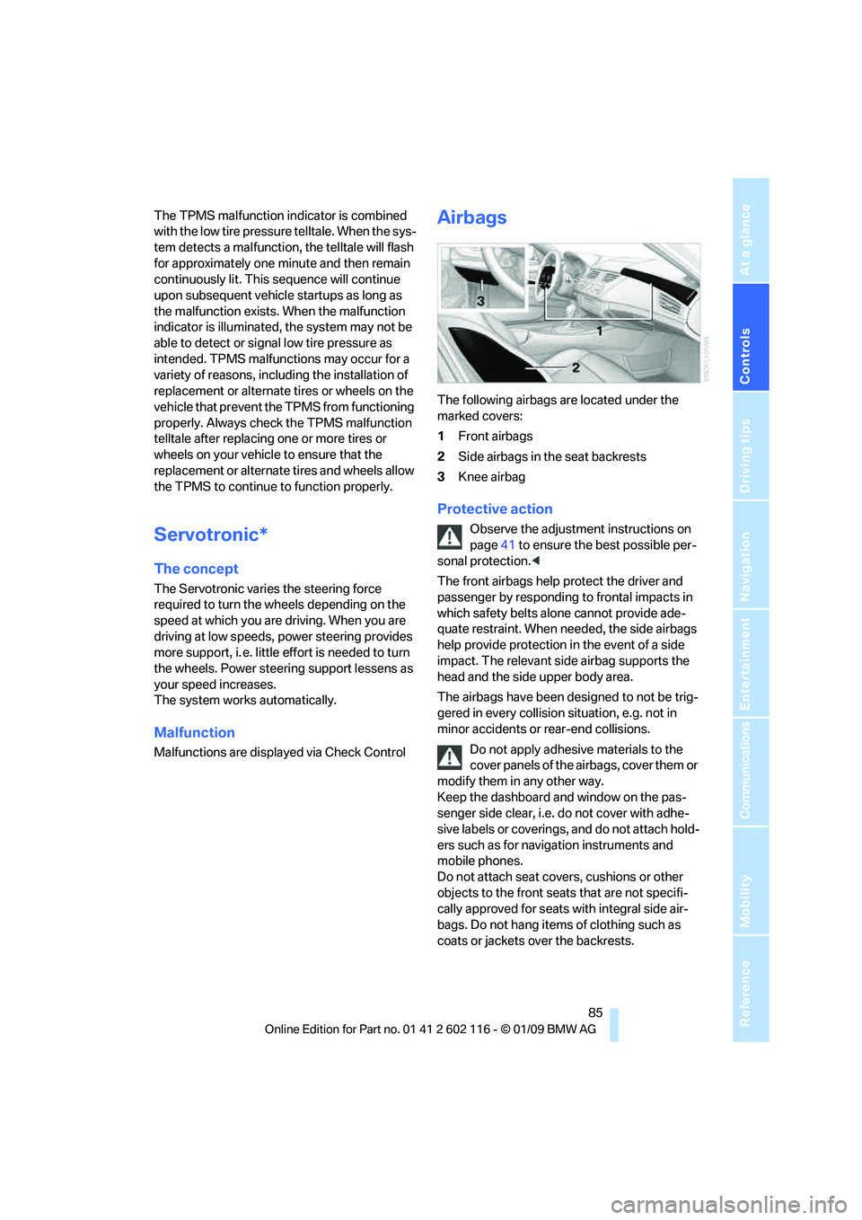
The following airbags are located under the
marked covers:
1 Front airbags
2 Side airbags in the seat backrests
3 Knee airbag
Protective action
Observe the adjustment instructions on
page 41 to ensure the best possible per-
sonal protection. <
The front airbags help protect the driver and
passenger by responding to frontal impacts in
which safety belts alone cannot provide ade-
quate restraint. When needed, the side airbags
help provide protection in the event of a side
impact. The relevant side airbag supports the
head and the side upper body area.
The airbags have been designed to not be trig-
gered in every collision situation, e.g. not in
minor accidents or rear-end collisions.
Do not apply adhesive materials to the
cover panels of the airbags, cover them or
modify them in any other way.
Keep the dashboard and window on the pas-
senger side clear, i.e. do not cover with adhe-
sive labels or coverings, and do not attach hold-
ers such as for navigation instruments and
mobile phones.
Do not attach seat cove rs, cushions or other
objects to the front seats that are not specifi-
cally approved for seats with integral side air-
bags. Do not hang items of clothing such as
coats or jackets over the backrests.
Page 89 of 248
Controls
87Reference
At a glance
Driving tips
Communications
Navigation
Entertainment
Mobility
After mounting a child seat, ensure that the
indicator lamp for the pa ssenger airbag is lit.
It indicates that the child seat has been
detected and that th e passenger airbags
are deactivated.
> The indicator lamp does not come on as
long as a person of sufficient size and in a
correct sitting position is detected on
the seat.
The front, knee and passenger airbags for
the passenger are activated.
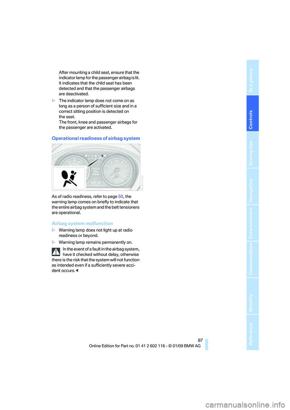
Operational readiness of airbag system
As of radio readiness, refer to page 50, the
warning lamp comes on br iefly to indicate that
the entire airbag system and the belt tensioners
are operational.
Airbag system malfunction
> Warning lamp does not light up at radio
readiness or beyond.
> Warning lamp remains permanently on.
In the event of a fault in the airbag system,
have it checked without delay, otherwise
there is the risk that th e system will not function
as intended even if a sufficiently severe acci-
dent occurs. <
Page 91 of 248
Controls
89Reference
At a glance
Driving tips
Communications
Navigation
Entertainment
Mobility
Welcome lamps are activated and are
stored for the remote control currently in use.
Pathway lighting
If you activate the head lamp flasher after park-
ing the car, with the lig hts switched off, the
low beams come on and remain on for a
certain time.
You can adjust the operating period or deacti-
vate the function.
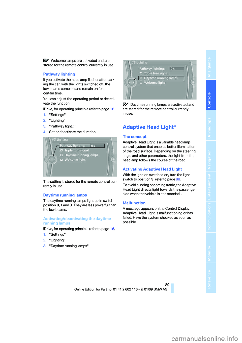
iDrive, for operating principle refer to page 16.
1. "Settings"
2. "Lighting"
3. "Pathway light.:"
4. Set or deactivate the duration.
The setting is stored for the remote control cur-
rently in use.
Daytime running lamps
The daytime running lamps light up in switch
position 0, 1 and 3. They are less powerful than
the low beams.
Activating/deactivating the daytime
running lamps
iDrive, for operating principle refer to page 16.
1. "Settings"
2. "Lighting"
3. "Daytime running lamps" Daytime running lamps are activated and
are stored for the remote control currently
in use.
Adaptive Head Light*
The concept
Adaptive Head Light is a variable headlamp
control system that en ables better illumination
of the road surface. Depending on the steering
angle and other parameters, the light from the
headlamp follows the course of the road.
Activating Adapti ve Head Light
With the ignition switched on, turn the light
switch to position 3, refer to page 88.
To avoid blinding oncoming traffic, the Adaptive
Head Light directs light towards the passenger
side when the vehicle is at a standstill.
Malfunction
A message appears on the Control Display.
Adaptive Head Light is malfunctioning or has
failed. Have the system checked as soon as
possible.