2009 BMW 525I TOURING lock
[x] Cancel search: lockPage 81 of 294

Controls
79Reference
At a glance
Driving tips
Communications
Navigation
Entertainment
Mobility
Everything under control
Odometer, outside
temperature display, clock,
date
1Time, outside temperature and date
2Odometer and trip odometer
3Press button:
>with ignition switched on, trip odometer
is reset
>with ignition switched off, time, outside
temperature, and odometer are briefly
displayed.
From radio readiness the outside temperature
and the time are displayed.
Date retrieval:
Press CHECK button on turn signal lever, refer
to page85.
Time and date setting, refer to page87.
You can set the unit of measure 7 or 6 on the
Control Display, refer to Units of measure on
page89.
Outside temperature warning
If the display drops to +377/+36, a signal
sounds and a warning lamp lights up. A mes-
sage appears on the Control Display. There is
an increased danger of ice.
Even at temperatures above +377/
+36 ice can form. Therefore, drive care-
fully, e.g. on bridges and sections of road in the
shade, otherwise there is an increased accident
risk.<
Tachometer
Avoid engine speeds in the white-striped
advance warning field, arrow1, if possible.
Be sure to avoid engine speeds in the red warn-
ing field, arrow2. At high revs in this range, the
flow of fuel is interrupted to protect the engine.
Coolant temperature
Should the coolant, and with it the engine
become too hot, a warning lamp lights up. In
addition, a message appears on the Control
Display.
Checking coolant level, refer to page235.
Page 93 of 294

Controls
91Reference
At a glance
Driving tips
Communications
Navigation
Entertainment
Mobility
1.Press the button.
This opens the start menu.
2.Press the controller to open the menu.
3.Turn the controller until "Settings" is
selected and press the controller.
4.Turn the controller until "Vehicle / Tires" is
selected and press the controller.
5.Change to upper field if necessary. Turn the
controller until "PDC" is selected and press
the controller.
6.Select "PDC display on" and press the con-
troller.
The PDC screen is activated.
The display appears on the Control Display as
soon as PDC is activated.
System limits
Even with PDC, final responsibility for
estimating the distance between the
vehicle and any obstructions always remains
with the driver. Even when sensors are pro-
vided, there is a blind spot in which objects can
no longer be detected. The system is also sub-
ject to the physical limits that apply to all forms
of ultrasonic measurement, such as those
encountered with tow bars and trailer cou-
plings, or thin and wedge-shaped objects etc. Low objects already displayed, e. g. curbs, can
also disappear from the detection area of the
sensors again before or after a continuous tone
already sounds. Higher, protruding objects, e.g.
ledges, cannot be detected. For this reason,
drive with care; otherwise, there is a danger of
personal injury or property damage.
Loud sources of sound, inside and outside the
vehicle, could drown out the PDC signal tone.<
Driving stability control
systems
Your BMW is equipped with an extended array
of systems designed to enhance and maintain
vehicle stability under extreme conditions.
ABS Antilock Brake System
ABS prevents locking of the wheels during
braking. Safe steering response is maintained
even during full braking. Active safety is thus
increased.
The ABS is operational every time you start the
engine. Braking safely refer to page136.
CBC Cornering Brake Control
When braking during curves or when braking
during a lane change, driving stability and steer-
ing response are improved further.
Electronic brake-force distribution
The system controls the brake pressure in the
rear wheels to ensure stable braking behavior.
Brake assistant
When you apply the brakes rapidly, this system
produces maximum braking force boosting and
thus helps to achieve the shortest possible
braking distance during full braking maneuvers.
This system exploits all of the benefits provided
by ABS.
Do not reduce the pressure on the brake pedal
for the duration of the full braking.
Page 106 of 294

Technology for comfort, convenience and safety
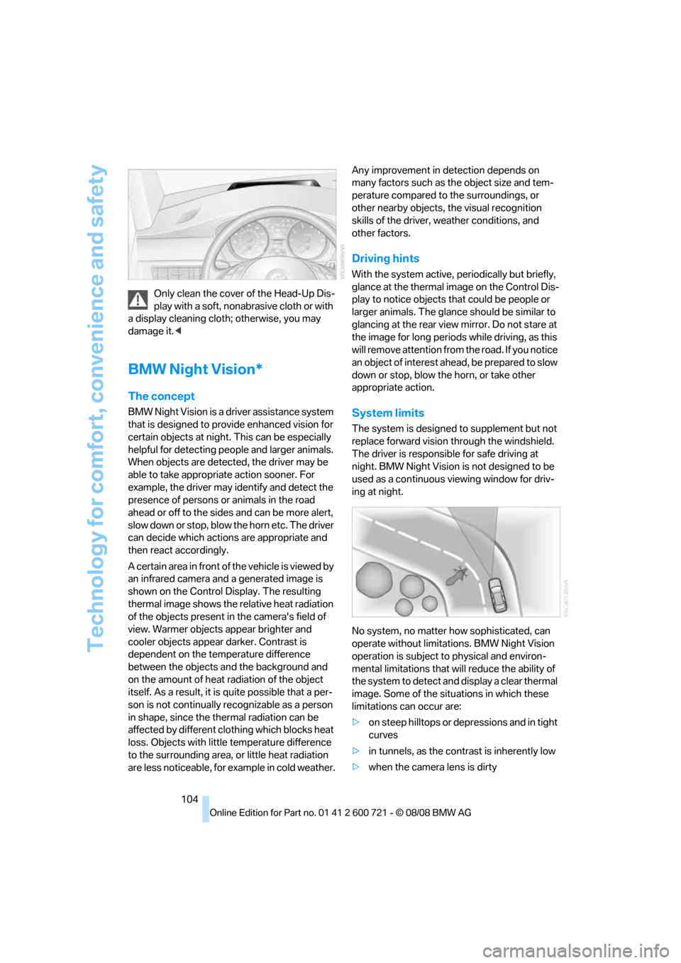
104 Only clean the cover of the Head-Up Dis-
play with a soft, nonabrasive cloth or with
a display cleaning cloth; otherwise, you may
damage it.<
BMW Night Vision*
The concept
BMW Night Vision is a driver assistance system
that is designed to provide enhanced vision for
certain objects at night. This can be especially
helpful for detecting people and larger animals.
When objects are detected, the driver may be
able to take appropriate action sooner. For
example, the driver may identify and detect the
presence of persons or animals in the road
ahead or off to the sides and can be more alert,
slow down or stop, blow the horn etc. The driver
can decide which actions are appropriate and
then react accordingly.
A certain area in front of the vehicle is viewed by
an infrared camera and a generated image is
shown on the Control Display. The resulting
thermal image shows the relative heat radiation
of the objects present in the camera's field of
view. Warmer objects appear brighter and
cooler objects appear darker. Contrast is
dependent on the temperature difference
between the objects and the background and
on the amount of heat radiation of the object
itself. As a result, it is quite possible that a per-
son is not continually recognizable as a person
in shape, since the thermal radiation can be
affected by different clothing which blocks heat
loss. Objects with little temperature difference
to the surrounding area, or little heat radiation
are less noticeable, for example in cold weather.Any improvement in detection depends on
many factors such as the object size and tem-
perature compared to the surroundings, or
other nearby objects, the visual recognition
skills of the driver, weather conditions, and
other factors.
Driving hints
With the system active, periodically but briefly,
glance at the thermal image on the Control Dis-
play to notice objects that could be people or
larger animals. The glance should be similar to
glancing at the rear view mirror. Do not stare at
the image for long periods while driving, as this
will remove attention from the road. If you notice
an ob je c t o f intere st ahea d, be pre pare d to slow
down or stop, blow the horn, or take other
appropriate action.
System limits
The system is designed to supplement but not
replace forward vision through the windshield.
The driver is responsible for safe driving at
night. BMW Night Vision is not designed to be
used as a continuous viewing window for driv-
ing at night.
No system, no matter how sophisticated, can
operate without limitations. BMW Night Vision
operation is subject to physical and environ-
mental limitations that will reduce the ability of
the system to detect and display a clear thermal
image. Some of the situations in which these
limitations can occur are:
>on steep hilltops or depressions and in tight
curves
>in tunnels, as the contrast is inherently low
>when the camera lens is dirty
Page 110 of 294

Lamps
108
Lamps
Parking lamps/low beams
0Lights off and daytime running lamps*
1Parking lamps and daytime running lamps*
2Low beams and welcome lamps
3Automatic headlamp control
*, daytime run-
ning lamps
*, welcome lamps, Adaptive
Head Light
* and high-beam assistant*
If you open the driver's door with the ignition
switched off, the exterior lighting is switched off
when the light switch is in position2 or 3. The
daytime running lamps have already been
switched off at the same time as the ignition.
For this reason, switch on the side marker
lamps as needed, switch position1; otherwise,
the vehicle is not lit.
Parking lamps
In switch position1, the front, rear and side
vehicle lighting is switched on. You can use the
parking lamps for parking.
The parking lamps drain the battery. Do
not leave them switched on for long peri-
ods of time, otherwise it may no longer be pos-
sible to start the engine. It is preferable to
switch on the roadside parking lamps on one
side, refer to page110.<
Low beams
The low beams light up when the light switch is
in position 2 and the ignition is on.
Automatic headlamp control*
In switch position3, the system activates the
low beams and switches them on or off in
response to changes in ambient light condi-
tions, for instance, in a tunnel, at dawn and dusk
and in case of precipitation. Adaptive Head
Light
* is active. The LED next to the symbol
lights up when the low beams are on. You can
also activate the daytime running lamps, refer to
page109. In the situations described above,
the lamps then switch to low beams.
A blue sky with the sun low on the horizon can
cause the lights to be switched on.
The low beams remain switched on inde-
pendent of the ambient lighting condi-
tions when you switch on the fog lamps
*.<
The automatic headlamp control cannot
serve as a substitute for your personal
judgment in determining when the lamps
should be switched on in response to ambient
lighting conditions. For example, the sensors
cannot detect fog of hazy weather. To avoid
safety risks, you should always switch on the
low beams manually under these conditions.<
Welcome lamps
If you leave the light switch in position2 or 3
when parking the vehicle, then when you unlock
the vehicle, the parking lamps and interior light-
ing remain illuminated for a brief time.
Activating/deactivating welcome
lamps
iDrive, for operating principle refer to page16.
1.Press the button.
This opens the start menu.
2.Press the controller to open the menu.
3.Select "Settings" and press the controller.
4.Select "Vehicle / Tires" and press the con-
troller.
Page 125 of 294

Controls
123Reference
At a glance
Driving tips
Communications
Navigation
Entertainment
Mobility
Sun blinds for rear side windows
Pull the loop of the roller sun blind and hook
onto bracket.
Do not open the window with the roller
sun blind deployed. Otherwise, there is a
risk of damage and injury at higher speeds.<
Glove compartment
Opening
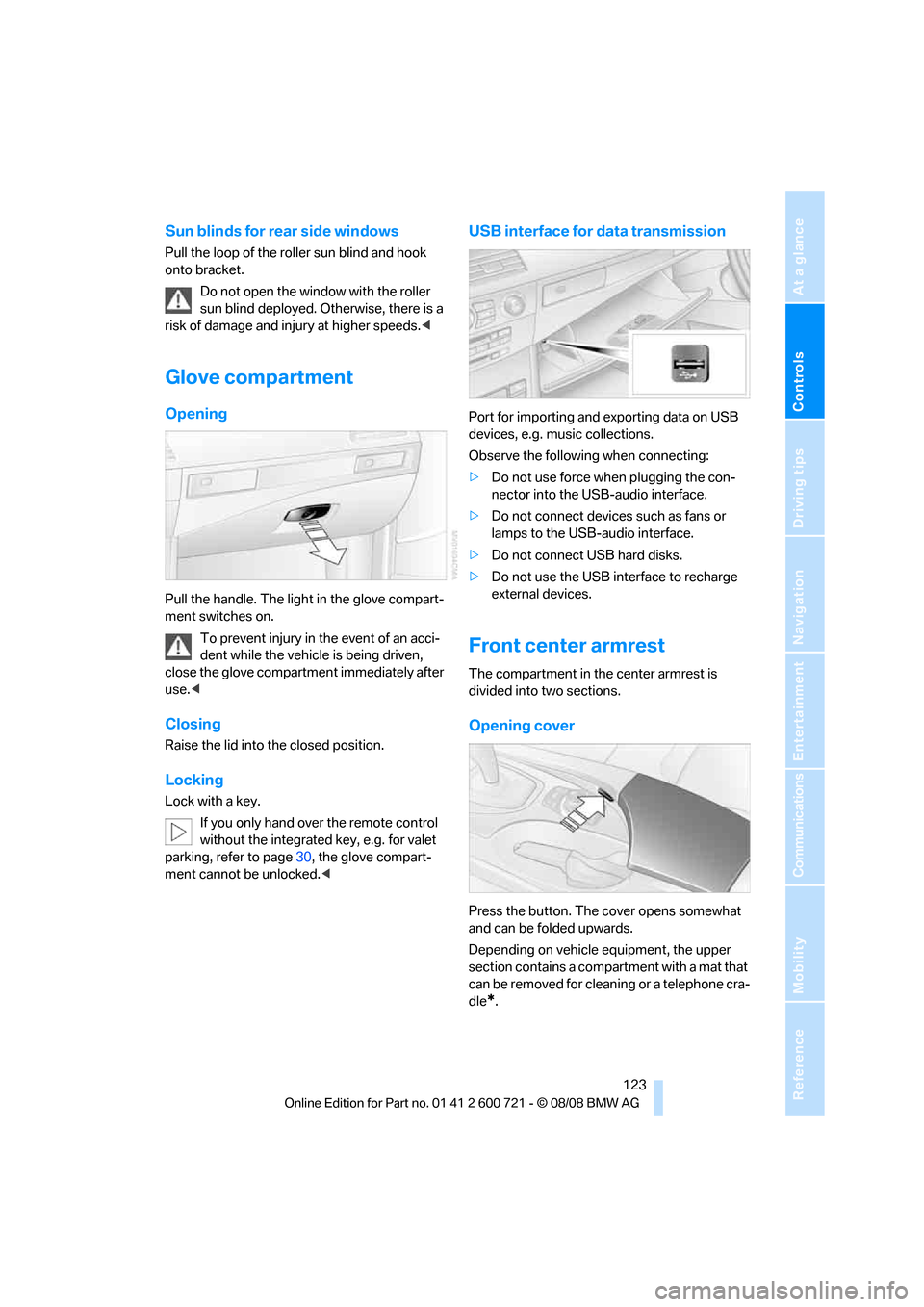
Pull the handle. The light in the glove compart-
ment switches on.
To prevent injury in the event of an acci-
dent while the vehicle is being driven,
close the glove compartment immediately after
use.<
Closing
Raise the lid into the closed position.
Locking
Lock with a key.
If you only hand over the remote control
without the integrated key, e.g. for valet
parking, refer to page30, the glove compart-
ment cannot be unlocked.<
USB interface for data transmission
Port for importing and exporting data on USB
devices, e.g. music collections.
Observe the following when connecting:
>Do not use force when plugging the con-
nector into the USB-audio interface.
>Do not connect devices such as fans or
lamps to the USB-audio interface.
>Do not connect USB hard disks.
>Do not use the USB interface to recharge
external devices.
Front center armrest
The compartment in the center armrest is
divided into two sections.
Opening cover
Press the button. The cover opens somewhat
and can be folded upwards.
Depending on vehicle equipment, the upper
section contains a compartment with a mat that
can be removed for cleaning or a telephone cra-
dle
*.
Page 129 of 294

Controls
127Reference
At a glance
Driving tips
Communications
Navigation
Entertainment
Mobility
In rear center console
Depending on the equipment, the sockets in
the rear are covered with caps or equipped with
a lighter. Refer to Cigarette lighter, front,
page125.
Access to socket:
Remove respective cap or lighter.
Center armrest, rear
Storage tray:
Pull the cover upward, arrow1.
Access to cup holders:
Press button2 and open the cover.
Sedan:
Through-loading system*
Opening
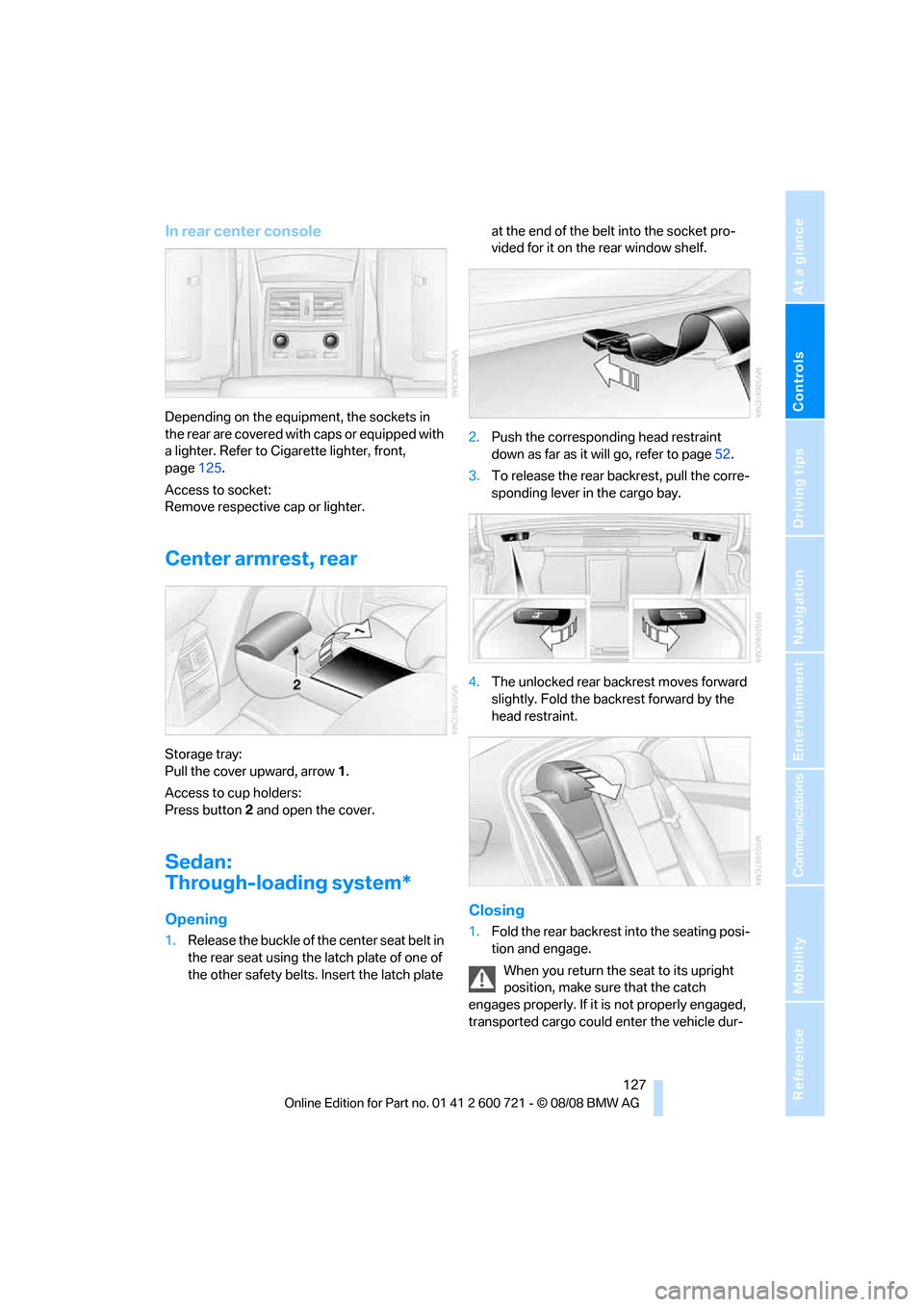
1.Release the buckle of the center seat belt in
the rear seat using the latch plate of one of
the other safety belts. Insert the latch plate at the end of the belt into the socket pro-
vided for it on the rear window shelf.
2.Push the corresponding head restraint
down as far as it will go, refer to page52.
3.To release the rear backrest, pull the corre-
sponding lever in the cargo bay.
4.The unlocked rear backrest moves forward
slightly. Fold the backrest forward by the
head restraint.
Closing
1.Fold the rear backrest into the seating posi-
tion and engage.
When you return the seat to its upright
position, make sure that the catch
engages properly. If it is not properly engaged,
transported cargo could enter the vehicle dur-
Page 131 of 294

Controls
129Reference
At a glance
Driving tips
Communications
Navigation
Entertainment
Mobility
With normal cargo bay
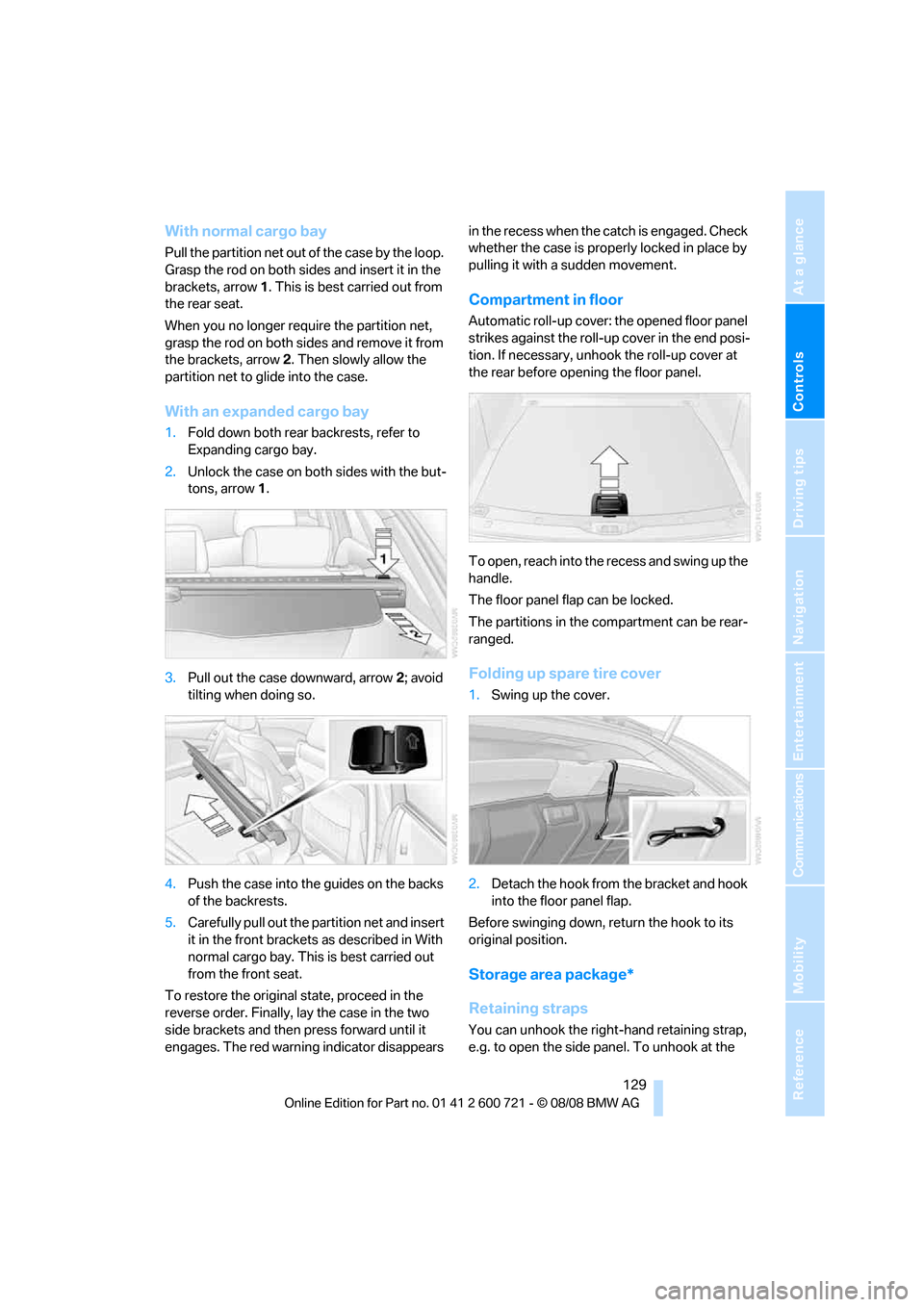
Pull the partition net out of the case by the loop.
Grasp the rod on both sides and insert it in the
brackets, arrow1. This is best carried out from
the rear seat.
When you no longer require the partition net,
grasp the rod on both sides and remove it from
the brackets, arrow2. Then slowly allow the
partition net to glide into the case.
With an expanded cargo bay
1.Fold down both rear backrests, refer to
Expanding cargo bay.
2.Unlock the case on both sides with the but-
tons, arrow1.
3.Pull out the case downward, arrow2; avoid
tilting when doing so.
4.Push the case into the guides on the backs
of the backrests.
5.Carefully pull out the partition net and insert
it in the front brackets as described in With
normal cargo bay. This is best carried out
from the front seat.
To restore the original state, proceed in the
reverse order. Finally, lay the case in the two
side brackets and then press forward until it
engages. The red warning indicator disappears in the recess when the catch is engaged. Check
whether the case is properly locked in place by
pulling it with a sudden movement.
Compartment in floor
Automatic roll-up cover: the opened floor panel
strikes against the roll-up cover in the end posi-
tion. If necessary, unhook the roll-up cover at
the rear before opening the floor panel.
To open, reach into the recess and swing up the
handle.
The floor panel flap can be locked.
The partitions in the compartment can be rear-
ranged.
Folding up spare tire cover
1.Swing up the cover.
2.Detach the hook from the bracket and hook
into the floor panel flap.
Before swinging down, return the hook to its
original position.
Storage area package*
Retaining straps
You can unhook the right-hand retaining strap,
e.g. to open the side panel. To unhook at the
Page 132 of 294

Practical interior accessories
130 rear end, pull downward; to hook in, press it into
the opening. In addition, it can also be secured
in the center. This makes it possible to secure
objects of different sizes.
Hooks
Two hooks can be used to secure smaller
objects.
Press at bottom and fold out until they lock.
Compartments in floor
Front compartment:
To open the flap, pull upward on the handle.
To close the flap, press downward until it locks.
Rear compartment:
To open, reach into the recess and swing up the
handle.
The rear flap can be locked.
Dividing up rear compartment
Fold out the partitions and press down.
Use the partition net, refer to page128.
Otherwise objects could be thrown
around and endanger occupants, e.g. during
braking or evasive maneuvers.<
Ski bag*
The ski bag is designed for safe, clean transport
of up to 4 pairs of standard skis or up to 2 snow-
boards.
With the ski bag you can stow skis with a length
o f u p t o 6 . 9 f t / 2 . 1 0 m . W h e n s k i s o f 6 . 9 f t / 2 . 1 0 m
in length are loaded, the ski bag will tend to con-
tract, reducing its overall capacity.
Loading
1.Fold down the center armrest, press the
button and open the cover.
2.Press the button again; the cover in the
cargo bay opens. If you press the button
firmly the first time, this also opens the
cover in the cargo bay.
3.Extend the ski bag between the front seats
and fill it. The zipper facilitates access to the
stowed items and drying of the ski bag.