2008 YAMAHA YZ250F brake
[x] Cancel search: brakePage 34 of 192

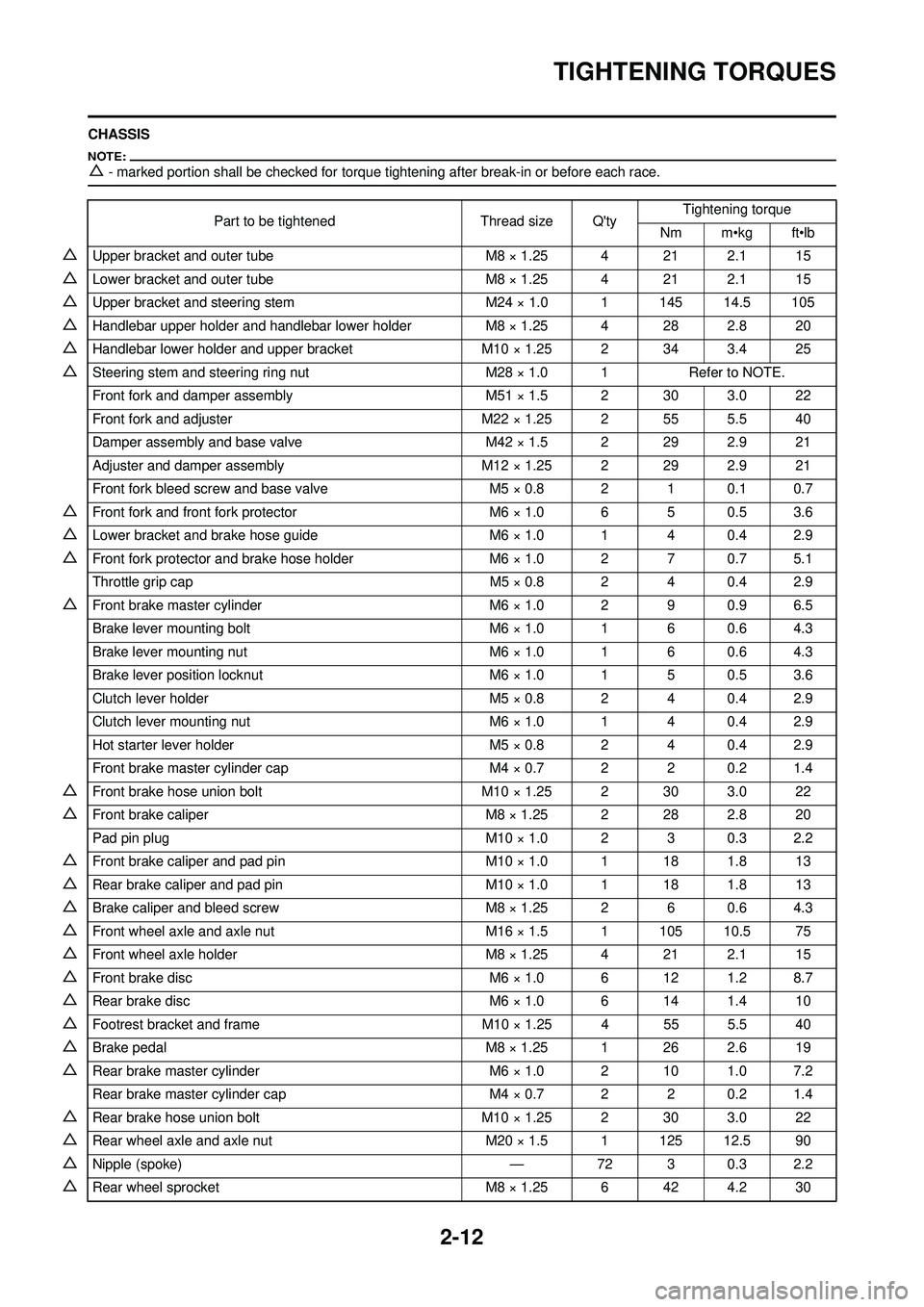
2-12
TIGHTENING TORQUES
CHASSIS
△- marked portion shall be checked for torque tightening after break-in or before each race.
Part to be tightenedThread size Q'tyTightening torque
Nm m•kg ft•lb
△Upper bracket and outer tube M8 × 1.25 4 21 2.1 15
△Lower bracket and outer tube M8 × 1.25 4 21 2.1 15
△Upper bracket and steering stem M24 × 1.0 1 145 14.5 105
△Handlebar upper holder and handlebar lower holderM8 × 1.25 4 28 2.8 20
△Handlebar lower holder and upper bracketM10 × 1.25 2 34 3.4 25
△Steering stem and steering ring nut M28 × 1.0 1Refer to NOTE.
Front fork and damper assembly M51 × 1.5 2 30 3.0 22
Front fork and adjuster M22 × 1.25 2 55 5.5 40
Damper assembly and base valve M42 × 1.5 2 29 2.9 21
Adjuster and damper assembly M12 × 1.25 2 29 2.9 21
Front fork bleed screw and base valve M5 × 0.8 2 1 0.1 0.7
△Front fork and front fork protector M6 × 1.0 6 5 0.5 3.6
△Lower bracket and brake hose guideM6 × 1.0 1 4 0.4 2.9
△Front fork protector and brake hose holderM6 × 1.0 2 7 0.7 5.1
Throttle grip cap M5 × 0.8 2 4 0.4 2.9
△Front brake master cylinderM6 × 1.0 2 9 0.9 6.5
Brake lever mounting bolt M6 × 1.0 1 6 0.6 4.3
Brake lever mounting nut M6 × 1.0 1 6 0.6 4.3
Brake lever position locknut M6 × 1.0 1 5 0.5 3.6
Clutch lever holder M5 × 0.8 2 4 0.4 2.9
Clutch lever mounting nut M6 × 1.0 1 4 0.4 2.9
Hot starter lever holder M5 × 0.8 2 4 0.4 2.9
Front brake master cylinder cap M4 × 0.7 2 2 0.2 1.4
△Front brake hose union boltM10 × 1.25 2 30 3.0 22
△Front brake caliper M8 × 1.25 2 28 2.8 20
Pad pin plug M10 × 1.0 2 3 0.3 2.2
△Front brake caliper and pad pinM10 × 1.0 1 18 1.8 13
△Rear brake caliper and pad pin M10 × 1.0 1 18 1.8 13
△Brake caliper and bleed screwM8 × 1.25 2 6 0.6 4.3
△Front wheel axle and axle nut M16 × 1.5 1 105 10.5 75
△Front wheel axle holderM8 × 1.25 4 21 2.1 15
△Front brake disc M6 × 1.0 6 12 1.2 8.7
△Rear brake disc M6 × 1.0 6 14 1.4 10
△Footrest bracket and frameM10 × 1.25 4 55 5.5 40
△Brake pedal M8 × 1.25 1 26 2.6 19
△Rear brake master cylinder M6 × 1.0 2 10 1.0 7.2
Rear brake master cylinder cap M4 × 0.7 2 2 0.2 1.4
△Rear brake hose union boltM10 × 1.25 2 30 3.0 22
△Rear wheel axle and axle nut M20 × 1.5 1 125 12.5 90
△Nipple (spoke) —72 3 0.3 2.2
△Rear wheel sprocket M8 × 1.25 6 42 4.2 30
Page 35 of 192

2-13
TIGHTENING TORQUES
△Rear brake disc coverM6 × 1.0 2 10 1.0 7.2
△Rear brake caliper protector M6 × 1.0 2 7 0.7 5.1
Drive chain puller adjust bolt and locknut M8 × 1.25 2 19 1.9 12
Engine mounting:
△Engine and engine bracket (front) M10 × 1.25 1 53 5.3 38
△Engine and frame (lower) M10 × 1.25 1 53 5.3 38
△Upper engine bracket and frame M8 × 1.25 4 34 3.4 25
△Lower engine bracket and frameM8 × 1.25 4 38 3.8 27
△Engine and engine bracket (upper)M10 × 1.25 1 55 5.5 40
Lower engine guard M6 × 1.0 3 10 1.0 7.2
△Right engine guardM6 × 1.0 1 10 1.0 7.2
CDI unit bracket M6 × 1.0 2 7 0.7 5.1
Cable guide and CDI unit bracket M5 × 0.8 2 4 0.4 2.9
Cable guide and frame M5 × 0.8 1 5 0.5 3.6
△Pivot shaft and nutM16 × 1.5 1 85 8.5 61
△Relay arm and swingarmM14 × 1.5 1 70 7.0 50
△Relay arm and connecting rod M14 × 1.5 1 80 8.0 58
△Connecting rod and frame M14 × 1.5 1 80 8.0 58
△Rear shock absorber and frameM10 × 1.25 1 56 5.6 40
△Rear shock absorber and relay armM10 × 1.25 1 53 5.3 38
△Rear frame (upper) M8 × 1.25 1 38 3.8 27
△Rear frame (lower) M8 × 1.25 2 32 3.2 23
△Swingarm and brake hose holder M5 × 0.8 4 2 0.2 1.4
Swingarm and patch M4 × 0.7 4 2 0.2 1.4
Upper drive chain tensioner M8 × 1.25 1 16 1.6 11
Lower drive chain tensioner M8 × 1.25 1 16 1.6 11
Drive chain support M6 × 1.0 3 7 0.7 5.1
△Seal guard and swingarmM5 × 0.8 4 6 0.6 4.3
△Fuel tank mounting boss and frameM10 × 1.25 1 20 2.0 14
△Fuel tank M6 × 1.0 2 9 0.9 6.5
△Fuel cockM6 × 1.0 2 4 0.4 2.9
Seat set bracket and fuel tank M6 × 1.0 1 7 0.7 5.1
Fuel tank bracket and fuel tank M6 × 1.0 4 7 0.7 5.1
△Air scoop and fuel tankM6 × 1.0 6 7 0.7 5.1
△Air scoop and radiator guard (lower) M6 × 1.0 2 7 0.7 5.1
△Front fenderM6 × 1.0 4 7 0.7 5.1
△Rear fender (front) M6 × 1.0 2 7 0.7 5.1
△Rear fender (rear) M6 × 1.0 2 16 1.6 11
△Side coverM6 × 1.0 2 7 0.7 5.1
Seat M8 × 1.25 2 23 2.3 17
△Number plate M6 × 1.0 1 7 0.7 5.1
Part to be tightened
Thread size Q'tyTightening torque
Nm m•kg ft•lb
Page 45 of 192

2-23
CABLE ROUTING DIAGRAM
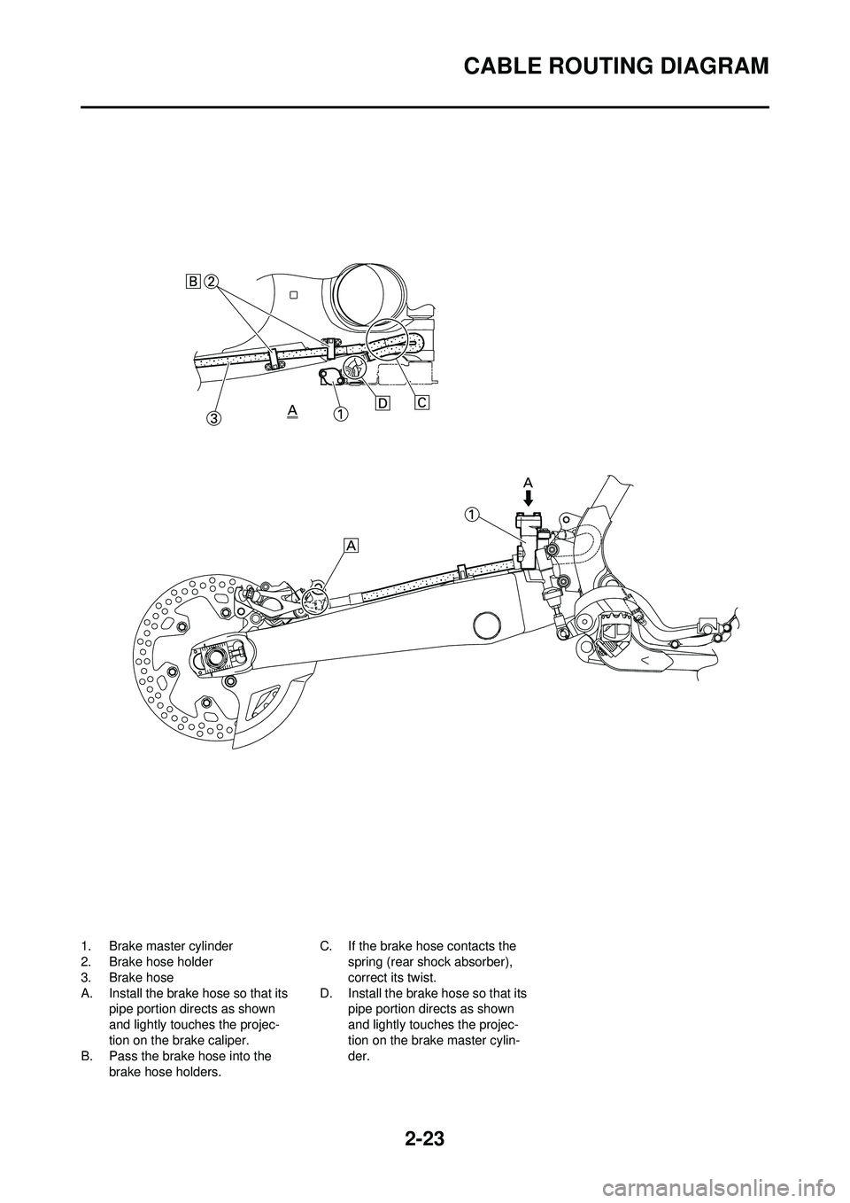
1. Brake master cylinder
2. Brake hose holder
3. Brake hose
A. Install the brake hose so that its pipe portion directs as shown
and lightly touches the projec-
tion on the brake caliper.
B. Pass the brake hose into the
brake hose holders. C. If the brake hose contacts the
spring (rear shock absorber),
correct its twist.
D. Install the brake hose so that its pipe portion directs as shown
and lightly touches the projec-
tion on the brake master cylin-
der.
Page 46 of 192

2-24
CABLE ROUTING DIAGRAM
1. Throttle cable
2. Clamp
3. Hot starter cable
4. Clutch cable
5. Engine stop switch lead
6. Cable guide
7. Brake hose
8. Hose guide
A. Fasten the engine stop switch lead to the handlebar. B. Pass the clutch cable and hot
starter cable through the cable
guide.
C. Pass the brake hose in front of the number plate.
D. Pass the throttle cables through the cable guide.
E. Pass the clutch cable and hot
starter cable through the cable
guide on the number plate.
Page 49 of 192

3-3
MAINTENANCE INTERVALS
OIL STRAINERClean
●
FRAMEClean and inspect
●●
FUEL TANK, COCKClean and inspect
●●
BRAKESAdjust lever position and pedal
height
●●
Lubricate pivot point●●
Check brake disc surface●●
Check fluid level and leakage●●
Retighten brake disc bolts, cali-
per bolts, master cylinder bolts
and union bolts●●
Replace pads●
Replace brake fluid●Every one year
FRONT FORKS Inspect and adjust
●●
Replace oil●●Suspension oil "S1"
Replace oil seal
●
FRONT FORK OIL SEAL AND
DUST SEAL Clean and lube
●●Lithium base grease
PROTECTOR GUIDE Replace
●
REAR SHOCK ABSORBERInspect and adjust
●●
Lube●
(After rain
ride)
●Molybdenum disulfide grease
Replace spring seat
●Every one year
Retighten
●●
DRIVE CHAIN GUIDE AND
ROLLERS Inspect
●●
SWINGARMInspect, lube and retighten
●●Molybdenum disulfide grease
RELAY ARM, CONNECTING
ROD Inspect, lube and retighten
●●Molybdenum disulfide grease
STEERING HEAD Inspect free play and retighten
●●
Clean and lube●Lithium base grease
Replace bearing
●
Item After
break-
in Every
race
Every third
(or 500 km) Every
fifth (or 1,000 km)
As re-
quired Remarks
Page 51 of 192

3-5
PRE-OPERATION INSPECTION AND MAINTENANCE
PRE-OPERATION INSPECTION AND MAINTENANCE
Before riding for break-in operation, practice or a race, make sure the machine is in good operating condition.
Before using this machine, check the following points.
GENERAL INSPECTION AND MAINTENANCEItem RoutinePage
Coolant Check that coolant is filled up to the radiator cap. Check the cool-
ing system for leakage. P.3-6 – 7
Fuel Check that a fresh gasoline is filled in the fuel tank. Check the fuel
line for leakage. P.1-8 – 9
Engine oil Check that the oil level is correct. Check the crankcase and oil line
for leakage. P.3-8 – 10
Gear shifter and clutch Check that gears can be shifted correctly in order and that the
clutch operates smoothly. P.3-7
Throttle grip/Housing Check that the throttle grip operation and free play are correctly
adjusted. Lubricate the throttle grip and housing, if necessary. P.3-7 – 8
Brakes Check the play of front brake and effect of front and rear brake. P.3-14 – 16
Drive chain Check drive chain slack and alignment. Check that the drive chain
is lubricated properly. P.3-17
Wheels Check for excessive wear and tire pressure. Check for loose
spokes and have no excessive play. P.3-20
Steering Check that the handlebar can be turned smoothly and have no ex-
cessive play. P.3-20 – 21
Front forks and rear shock
absorber Check that they operate smoothly and there is no oil leakage.
P.3-18 – 20
Cables (wires) Check that the clutch and throttle cables move smoothly. Check
that they are not caught when the handlebars are turned or when
the front forks travel up and down.
—
Exhaust pipe Check that the exhaust pipe is tightly mounted and has no cracks. P.4-3 – 4
Rear wheel sprocket Check that the rear wheel sprocket tightening bolt is not loose. P.3-16 – 17
Lubrication Check for smooth operation. Lubricate if necessary. P.3-22
Bolts and nuts Check the chassis and engine for loose bolts and nuts. P.1-11
Lead connectors Check that the CDI magneto, CDI unit, and ignition coil are con-
nected tightly. P.1-3
Settings Is the machine set suitably for the condition of the racing course
and weather or by taking into account the results of test runs be-
fore racing? Are inspection and maintenance completely done?
P.7-1 – 10
Page 60 of 192

3-14
CHASSIS
CHASSIS
BLEEDING THE HYDRAULIC
BRAKE SYSTEM
Bleed the brake system if:
• The system has been disassem-bled.
• A brake hose has been loosened or removed.
• The brake fluid is very low.
• The brake operation is faulty.
A dangerous loss of braking per-
formance may occur if the brake
system is not properly bled.
1. Remove: • Brake master cylinder cap
• Diaphragm
• Reservoir float (front brake)
• Protector (rear brake)
2. Bleed: • Brake fluid
Air bleeding steps:
a. Add proper brake fluid to the res-
ervoir.
b. Install the diaphragm. Be careful
not to spill any fluid or allow the
reservoir to overflow.
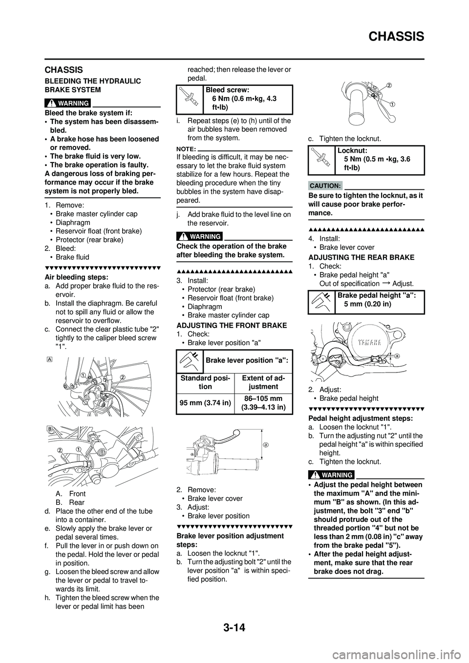
c. Connect the clear plastic tube "2"
tightly to the caliper bleed screw
"1".
A. Front
B. Rear
d. Place the other end of the tube into a container.
e. Slowly apply the brake lever or pedal several times.
f. Pull the lever in or push down on
the pedal. Hold the lever or pedal
in position.
g. Loosen the bleed screw and allow
the lever or pedal to travel to-
wards its limit.
h. Tighten the bleed screw when the
lever or pedal limit has been reached; then release the lever or
pedal.
i. Repeat steps (e) to (h) until of the air bubbles have been removed
from the system.
If bleeding is difficult, it may be nec-
essary to let the brake fluid system
stabilize for a few hours. Repeat the
bleeding procedure when the tiny
bubbles in the system have disap-
peared.
j. Add brake fluid to the level line on
the reservoir.
Check the operation of the brake
after bleeding the brake system.
3. Install:• Protector (rear brake)
• Reservoir float (front brake)
• Diaphragm
• Brake master cylinder cap
ADJUSTING THE FRONT BRAKE
1. Check: • Brake lever position "a"
2. Remove: • Brake lever cover
3. Adjust: • Brake lever position
Brake lever position adjustment
steps:
a. Loosen the locknut "1".
b. Turn the adjusting bolt "2" until the lever position "a" is within speci-
fied position. c. Tighten the locknut.
Be sure to tighten the locknut, as it
will cause poor brake perfor-
mance.
4. Install:
• Brake lever cover
ADJUSTING THE REAR BRAKE
1. Check: • Brake pedal height "a"Out of specification
→Adjust.
2. Adjust: • Brake pedal height
Pedal height adjustment steps:
a. Loosen the locknut "1".
b. Turn the adjusting nut "2" until the pedal height "a" is within specified
height.
c. Tighten the locknut.
• Adjust the pedal height between the maximum "A" and the mini-
mum "B" as shown. (In this ad-
justment, the bolt "3" end "b"
should protrude out of the
threaded portion "4" but not be
less than 2 mm (0.08 in) "c" away
from the brake pedal "5").
• After the pedal height adjust-
ment, make sure that the rear
brake does not drag.
Bleed screw: 6 Nm (0.6 m•kg, 4.3
ft•lb)
Brake lever position "a":
Standard posi- tion Extent of ad-
justment
95 mm (3.74 in) 86–105 mm
(3.39–4.13 in)
Locknut: 5 Nm (0.5 m •kg, 3.6
ft•lb)
Brake pedal height "a": 5 mm (0.20 in)
Page 61 of 192

3-15
CHASSIS
CHECKING AND REPLACING THE
FRONT BRAKE PADS
1. Inspect:• Brake pad thickness "a"Out of specification
→Replace as
a set.
2. Replace: •Brake pad
Brake pad replacement steps:
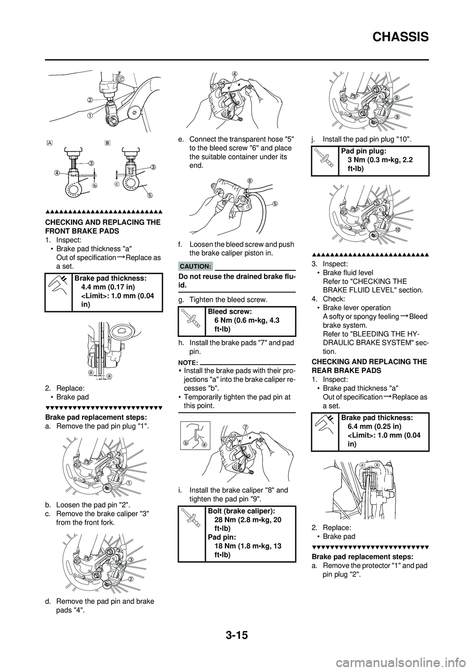
a. Remove the pad pin plug "1".
b. Loosen the pad pin "2".
c. Remove the brake caliper "3" from the front fork.
d. Remove the pad pin and brake pads "4". e. Connect the transparent hose "5"
to the bleed screw "6" and place
the suitable container under its
end.
f. Loosen the bleed screw and push the brake caliper piston in.
Do not reuse the drained brake flu-
id.
g. Tighten the bleed screw.
h. Install the brake pads "7" and pad
pin.
�ŒInstall the brake pads with their pro-
jections "a" into the brake caliper re-
cesses "b".
• Temporarily tighten the pad pin at this point.
i. Install the brake caliper "8" and
tighten the pad pin "9". j. Install the pad pin plug "10".
3. Inspect:
• Brake fluid levelRefer to "CHECKING THE
BRAKE FLUID LEVEL" section.
4. Check: • Brake lever operationA softy or spongy feeling
→Bleed
brake system.
Refer to "BLEEDING THE HY-
DRAULIC BRAKE SYSTEM" sec-
tion.
CHECKING AND REPLACING THE
REAR BRAKE PADS
1. Inspect: • Brake pad thickness "a"
Out of specification
→Replace as
a set.
2. Replace: • Brake pad
Brake pad replacement steps:
a. Remove the protector "1" and pad pin plug "2".
Brake pad thickness:
4.4 mm (0.17 in)
in)
Bleed screw:6 Nm (0.6 m•kg, 4.3
ft•lb)
Bolt (brake caliper): 28 Nm (2.8 m•kg, 20
ft•lb)
Pad pin: 18 Nm (1.8 m•kg, 13
ft•lb)
Pad pin plug:3 Nm (0.3 m•kg, 2.2
ft•lb)
Brake pad thickness: 6.4 mm (0.25 in)
in)