2008 YAMAHA YZ250F transmission oil
[x] Cancel search: transmission oilPage 10 of 192

CONTENTS
CHAPTER 1
GENERAL INFOR-
MATION
DESCRIPTION ................. 1-1
MACHINE
IDENTIFICATION ............. 1-2
INCLUDED PARTS .......... 1-2
IMPORTANT
INFORMATION................. 1-2
CHECKING OF
CONNECTION .................. 1-3
SPECIAL TOOLS ............. 1-4
CONTROL FUNCTIONS .. 1-8
STARTING AND
BREAK-IN ........................ 1-8
TORQUE-CHECK
POINTS........................... 1-11
CLEANING AND
STORAGE ...................... 1-12
CHAPTER 2
SPECIFICATIONS
GENERAL
SPECIFICATIONS ............ 2-1
MAINTENANCE
SPECIFICATIONS ............ 2-3
TIGHTENING
TORQUES ...................... 2-10
LUBRICATION
DIAGRAMS .................... 2-16
CABLE ROUTING
DIAGRAM ....................... 2-18
CHAPTER 3
REGULAR INSPEC-
TION AND AD-JUSTMENTS
MAINTENANCE
INTERVALS ...................... 3-1
PRE-OPERATION
INSPECTION AND
MAINTENANCE................ 3-5
ENGINE ............................ 3-6
CHASSIS ........................ 3-14
ELECTRICAL ................. 3-23
CHAPTER 4 ENGINE
SEAT, FUEL TANK AND
SIDE COVERS.................. 4-1
EXHAUST PIPE AND
SILENCER ........................ 4-3
RADIATOR ....................... 4-5
CARBURETOR................. 4-7
CAMSHAFTS.................. 4-14
CYLINDER HEAD........... 4-19
VALVES AND VALVE
SPRINGS ........................ 4-21
CYLINDER AND
PISTON ........................... 4-25
CLUTCH ......................... 4-29
OIL FILTER ELEMENT
AND WATER PUMP ....... 4-34
BALANCER .................... 4-38
OIL PUMP ....................... 4-40
KICK SHAFT AND
SHIFT SHAFT ................. 4-44
CDI MAGNETO............... 4-49
ENGINE REMOVAL ....... 4-51
CRANKCASE AND
CRANKSHAFT ............... 4-55
TRANSMISSION, SHIFT
CAM AND SHIFT
FORK .............................. 4-61
CHAPTER 5CHASSIS
FRONT WHEEL AND
REAR WHEEL ..................5-1
FRONT BRAKE AND
REAR BRAKE ..................5-6
FRONT FORK ................. 5-16
HANDLEBAR..................5-24
STEERING ......................5-28
SWINGARM ....................5-32
REAR SHOCK
ABSORBER ....................5-37
CHAPTER 6
ELECTRICAL
ELECTRICAL
COMPONENTS AND
WIRING DIAGRAM ...........6-1
IGNITION SYSTEM...........6-2
THROTTLE POSITION
SENSOR SYSTEM ...........6-5
CHAPTER 7
TUNING
ENGINE.............................7-1
CHASSIS ..........................7-6
Page 22 of 192

1-12
CLEANING AND STORAGE
CLEANING AND STORAGE
CLEANING
Frequent cleaning of your machine
will enhance its appearance, maintain
good overall performance, and ex-
tend the life of many components.
1. Before washing the machine, block off the end of the exhaust
pipe to prevent water from enter-
ing. A plastic bag secured with a
rubber band may be used for this
purpose.
2. If the engine is excessively greasy, apply some degreaser to
it with a paint brush. Do not apply
degreaser to the chain, sprockets,
or wheel axles.
3. Rinse the dirt and degreaser off with a garden hose; use only
enough pressure to do the job.
Excessive hose pressure may
cause water seepage and contami-
nation of wheel bearings, front
forks, brakes and transmission
seals. Many expensive repair bills
have resulted from improper high
pressure detergent applications
such as those available in coin-op-
erated car washers.
4. After the majority of the dirt has been hosed off, wash all surfaces
with warm water and a mild deter-
gent. Use an old toothbrush to
clean hard-to-reach places.
5. Rinse the machine off immediate- ly with clean water, and dry all
surfaces with a soft towel or cloth.
6. Immediately after washing, re- move excess water from the
chain with a paper towel and lubri-
cate the chain to prevent rust.
7. Clean the seat with a vinyl uphol- stery cleaner to keep the cover
pliable and glossy.
8. Automotive wax may be applied to all painted or chromed surfac-
es. Avoid combination cleaner-
waxes, as they may contain abra-
sives.
9. After completing the above, start the engine and allow it to idle for
several minutes.
STORAGE
If your machine is to be stored for 60
days or more, some preventive mea-
sures must be taken to avoid deterio-
ration. After cleaning the machine
thoroughly, prepare it for storage as
follows:
1. Drain the fuel tank, fuel lines, and the carburetor float bowl.
2. Remove the spark plug, pour a ta- blespoon of SAE 10W-30 motor
oil in the spark plug hole, and re-
install the plug. With the engine
stop switch pushed in, kick the en-
gine over several times to coat the
cylinder walls with oil.
3. Remove the drive chain, clean it thoroughly with solvent, and lubri-
cate it. Reinstall the chain or store
it in a plastic bag tied to the frame.
4. Lubricate all control cables.
5. Block the frame up to raise the
wheels off the ground.
6. Tie a plastic bag over the exhaust
pipe outlet to prevent moisture
from entering.
7. If the machine is to be stored in a
humid or salt-air environment,
coat all exposed metal surfaces
with a film of light oil. Do not apply
oil to rubber parts or the seat cov-
er.
Make any necessary repairs before
the machine is stored.
Page 24 of 192

2-2
GENERAL SPECIFICATIONS
Fuel:Type Premium unleaded gasoline only with a research octane
number of 95 or higher.
Tank capacity 7.0 L (1.54 Imp gal, 1.85 US gal)
Carburetor: Type FCR-MX37
Manufacturer KEIHIN
Spark plug: Type/manufacturer CR8E/NGK (resistance type)
Gap 0.7–0.8 mm (0.028–0.031 in)
Clutch type: Wet, multiple-disc
Transmission: Primary reduction system Gear
Primary reduction ratio 57/17 (3.353)
Secondary reduction system Chain drive
Secondary reduction ratio 49/13 (3.769)
Transmission type Constant mesh, 5-speed
Operation Left foot operation
Gear ratio: 1st 30/14 (2.143)
2nd 28/16 (1.750)
3rd 29/20 (1.450)
4th 27/22 (1.227)
5th 25/24 (1.042)
Chassis: USA, CDN, AUS, NZ, ZAEUROPE
Frame type Semi double cradle
←
Caster angle27.1°26.9°
Trail 116.9 mm (4.60 in) 115.1 mm (4.53 in)
Tire: Type With tube
Size (front) 80/100-21 51M
Size (rear) 100/90-19 57M
Tire pressure (front and rear) 100 kPa (1.0 kgf/cm
2, 15 psi)
Brake: Front brake type Single disc brake
Operation Right hand operation
Rear brake type Single disc brake
Operation Right foot operation
Suspension: Front suspension Telescopic fork
Rear suspension Swingarm (link type monocross suspension)
Shock absorber: Front shock absorber Coil spring/oil damper
Rear shock absorber Coil spring/gas, oil damper
Wheel travel: Front wheel travel 300 mm (11.8 in)
Page 48 of 192

3-2
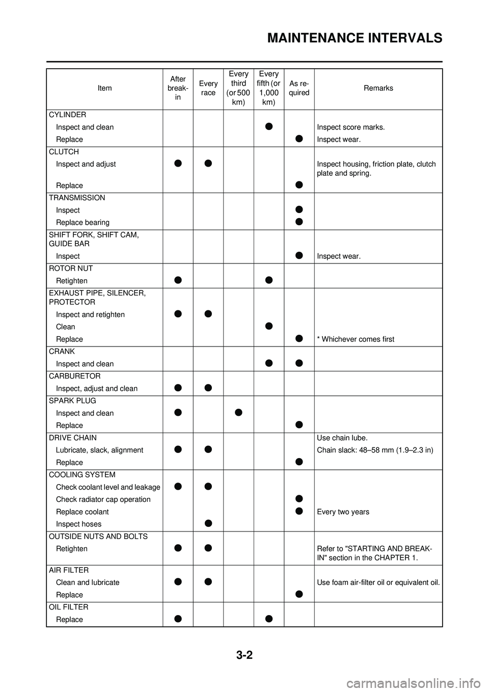
MAINTENANCE INTERVALS
CYLINDERInspect and clean
●Inspect score marks.
Replace
●Inspect wear.
CLUTCH Inspect and adjust
●●Inspect housing, friction plate, clutch
plate and spring.
Replace
●
TRANSMISSION Inspect
●
Replace bearing●
SHIFT FORK, SHIFT CAM,
GUIDE BARInspect
●Inspect wear.
ROTOR NUT Retighten
●●
EXHAUST PIPE, SILENCER,
PROTECTORInspect and retighten
●●
Clean●
Replace●* Whichever comes first
CRANK Inspect and clean
●●
CARBURETORInspect, adjust and clean
●●
SPARK PLUGInspect and clean
●●
Replace●
DRIVE CHAIN Use chain lube.
Lubricate, slack, alignment
●●Chain slack: 48–58 mm (1.9–2.3 in)
Replace
●
COOLING SYSTEM Check coolant level and leakage
●●
Check radiator cap operation●
Replace coolant●Every two years
Inspect hoses
●
OUTSIDE NUTS AND BOLTS Retighten
●●Refer to "STARTING AND BREAK-
IN" section in the CHAPTER 1.
AIR FILTER Clean and lubricate
●●Use foam air-filter oil or equivalent oil.
Replace
●
OIL FILTER Replace
●●
Item After
break-
in Every
race
Every third
(or 500 km) Every
fifth (or 1,000 km)
As re-
quired Remarks
Page 105 of 192

4-36
OIL FILTER ELEMENT AND WATER PUMP
REMOVING THE IMPELLER
SHAFT
1. Remove:•Impeller "1"
• Washer "2"
• Impeller shaft "3"
Hold the impeller shaft on its width
across the flats "a" with spanners,
etc. and remove the impeller.
REMOVING THE OIL SEAL
It is not necessary to disassemble the
water pump, unless there is an abnor-
mality such as excessive change in
coolant level, discoloration of coolant,
or milky transmission oil.
1. Remove:
• Bearing "1"
2. Remove: •Oil seal "1"
CHECKING THE OIL DELIVERY
PIPE
1. Inspect: • Oil delivery pipe "1"Bend/damage
→Replace.
Clogged
→Blow. CHECKING THE IMPELLER SHAFT
1. Inspect:
• Impeller shaft "1"Bend/wear/damage
→Replace.
Fur deposits
→Clean.
CHECKING THE IMPELLER SHAFT
GEAR
1. Inspect: • Gear teeth "a"Wear/damage
→Replace.
CHECKING THE BEARING
1. Inspect: • BearingRotate inner race with a finger.
Rough spot/seizure
→Replace.
CHECKING THE OIL SEAL
1. Inspect: • Oil seal "1"
Wear/damage
→Replace.
INSTALLING THE OIL SEAL
1. Install: • Oil seal "1"
• Apply the lithium soap base grease on the oil seal lip.
• Install the oil seal with its manufac- ture's marks or numbers facing the
right crankcase cover "2".
2. Install:• Bearing "1"
Install the bearing by pressing its out-
er race parallel.
INSTALLING THE IMPELLER
SHAFT
1. Install:• Impeller shaft "1"
• Washer "2"
• Impeller "3"
• Take care so that the oil seal lip is
not damaged or the spring does not
slip off its position.
• When installing the impeller shaft, apply the lithium soap base grease
on the oil seal lip and impeller shaft.
And install the shaft while turning it.
• Hold the impeller shaft on its width across the flats "a" with spanners,
etc. and install the impeller.
Impeller: 14 Nm (1.4 m•kg, 10
ft•lb)
Page 126 of 192

4-57
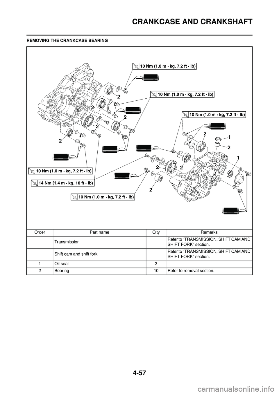
CRANKCASE AND CRANKSHAFT
REMOVING THE CRANKCASE BEARINGOrder Part name Q'ty Remarks Transmission Refer to "TRANSMISSION, SHIFT CAM AND
SHIFT FORK" section.
Shift cam and shift fork Refer to "TRANSMISSION, SHIFT CAM AND
SHIFT FORK" section.
1 Oil seal 2
2 Bearing 10 Refer to removal section.
Page 127 of 192

4-58
CRANKCASE AND CRANKSHAFT
DISASSEMBLING THE
CRANKCASE
1. Separate:• Right crankcase
• Left crankcase
Separation steps:
a. Remove the crankcase bolts "1", hose guide "2" and clutch cable
holder "3".
Loosen each bolt 1/4 of a turn at a
time and after all the bolts are loos-
ened, remove them.
b. Remove the right crankcase "4".
• Place the crankcase with its left half
downward and split the right half
apart while lifting it horizontally by
lightly tapping the projection "a" on
it using a soft hammer.
• When splitting it, leave the crank-
shaft and transmission with the left
half.
Use soft hammer to tap on the
case half. Tap only on reinforced
portions of case. Do not tap on
gasket mating surface. Work slow-
ly and carefully. Make sure the
case halves separate evenly. If the
cases do not separate, check for a
remaining case bolt or fitting. Do
not force.
c. Remove the dowel pins and O- ring.
REMOVING THE CRANKSHAFT
1. Remove:• Crankshaft "1"Use the crankcase separating
tool "2".
Do not use a hammer to drive out
the crankshaft.
REMOVING THE CRANKCASE
BEARING
1. Remove:• Bearing "1"
• Remove the bearing from the
crankcase by pressing its inner
race.
• Do not use the removed bearing.
CHECKING THE TIMING CHAIN
AND TIMING CHAIN GUIDE
1. Inspect:
•Timing chainCracks/stiff
→Replace the timing
chain and camshaft sprocket as a
set.
2. Inspect: • Timing chain guide
Wear/damage
→Replace.
CHECKING THE CRANKCASE
1. Inspect: • Contacting surface "a"Scratches
→Replace.
• Engine mounting boss "b", crank- case
Cracks/damage
→Replace. 2. Inspect:
• BearingRotate inner race with a finger.
Rough spot/seizure
→Replace.
3. Inspect: •Oil seal
Damage
→Replace.
CHECKING THE CRANKSHAFT
1. Measure: • Runout limit "a"
• Small end free play limit "b"
• Connecting rod big end side clearance "c"
• Crank width "d" Out of specification
→Replace.
Use the dial gauge and a thick-
ness gauge.
Crankcase separating
tool: YU-1135-A/90890-
01135
Dial gauge and stand:YU-3097/90890-01252
Standard
Runou
t limit: 0.03 mm (0.0012
in) 0.05
mm
(0.002
in)
Small
end
free
play: 0.4–1.0 mm
(0.016–0.039 in) 2.0 mm
(0.08 in)
Side
clear-
ance: 0.15–0.45 mm
(0.0059–0.0177 in) 0.50
mm
(0.02 in)
Crack
width: 55.95–56.00
mm (2.203– 2.205 in) —
Page 128 of 192

4-59
CRANKCASE AND CRANKSHAFT
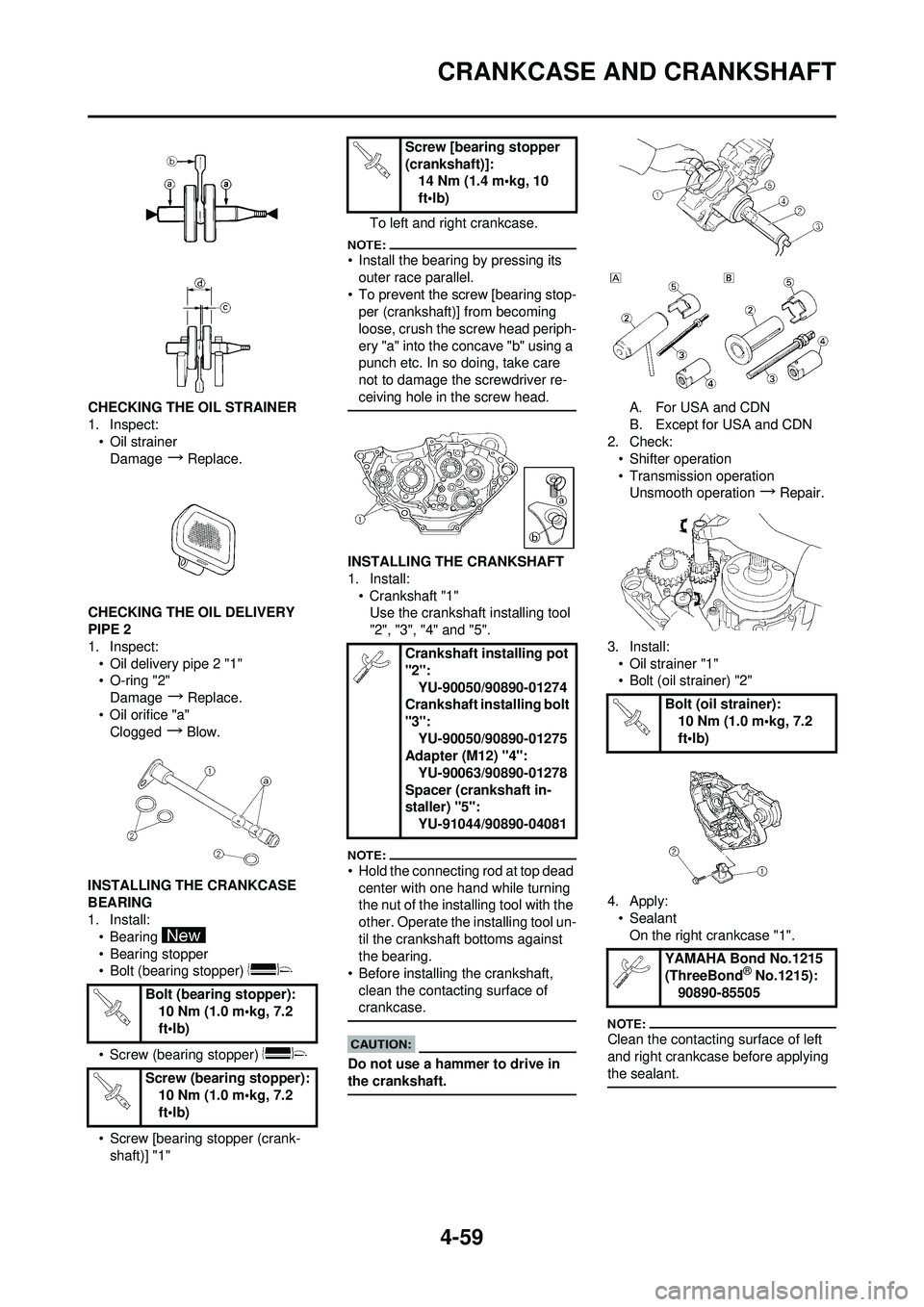
CHECKING THE OIL STRAINER
1. Inspect:• Oil strainer
Damage
→Replace.
CHECKING THE OIL DELIVERY
PIPE 2
1. Inspect: • Oil delivery pipe 2 "1"
• O-ring "2"Damage
→Replace.
• Oil orifice "a" Clogged
→Blow.
INSTALLING THE CRANKCASE
BEARING
1. Install: • Bearing
• Bearing stopper
• Bolt (bearing stopper)
• Screw (bearing stopper)
• Screw [bearing stopper (crank-shaft)] "1" To left and right crankcase.
• Install the bearing by pressing its
outer race parallel.
• To prevent the screw [bearing stop- per (crankshaft)] from becoming
loose, crush the screw head periph-
ery "a" into the concave "b" using a
punch etc. In so doing, take care
not to damage the screwdriver re-
ceiving hole in the screw head.
INSTALLING THE CRANKSHAFT
1. Install:
• Crankshaft "1"Use the crankshaft installing tool
"2", "3", "4" and "5".
• Hold the connecting rod at top dead
center with one hand while turning
the nut of the installing tool with the
other. Operate the installing tool un-
til the crankshaft bottoms against
the bearing.
• Before installing the crankshaft, clean the contacting surface of
crankcase.
Do not use a hammer to drive in
the crankshaft.
A. For USA and CDN
B. Except for USA and CDN
2. Check:
• Shifter operation
• Transmission operationUnsmooth operation
→Repair.
3. Install: • Oil strainer "1"
• Bolt (oil strainer) "2"
4. Apply: •SealantOn the right crankcase "1".
Clean the contacting surface of left
and right crankcase before applying
the sealant.
Bolt (bearing stopper): 10 Nm (1.0 m•kg, 7.2
ft•lb)
Screw (bearing stopper): 10 Nm (1.0 m•kg, 7.2
ft•lb)
Screw [bearing stopper
(crankshaft)]:14 Nm (1.4 m•kg, 10
ft•lb)
Crankshaft installing pot
"2": YU-90050/90890-01274
Crankshaft installing bolt
"3":
YU-90050/90890-01275
Adapter (M12) "4":
YU-90063/90890-01278
Spacer (crankshaft in-
staller) "5": YU-91044/90890-04081
Bolt (oil strainer):10 Nm (1.0 m•kg, 7.2
ft•lb)
YAMAHA Bond No.1215
(ThreeBond
® No.1215):
90890-85505