2008 YAMAHA YZ250F compression
[x] Cancel search: compressionPage 23 of 192

2-1
GENERAL SPECIFICATIONS
SPECIFICATIONS
GENERAL SPECIFICATIONS
Model name:YZ250FX (USA, CDN, AUS, NZ)
YZ250F (EUROPE, ZA)
Model code number: 5XCL (USA,CDN)
5XCM (EUROPE)
5XCP (AUS, NZ, ZA)
Dimensions: USA, CDN, ZA, AUS, NZEUROPE
Overall length 2,162 mm (85.12 in) 2,165 mm (85.24 in)
Overall width 825 mm (32.48 in)
←
Overall height1,300 mm (51.18 in)←
Seat height 985 mm (38.78 in)997 mm (39.25 in)
Wheelbase 1,469 mm (57.83 in)
←
Minimum ground clearance370 mm (14.57 in)372 mm (14.65 in)
Dry weight: Without oil and fuel 92.7 kg (204 lb)
Engine: Engine type Liquid cooled 4-stroke, DOHC
Cylinder arrangement Single cylinder, forward inclined
Displacement 249 cm
3 (8.76 Imp oz, 8.42 US oz)
Bore × stroke 77.0 × 53.6 mm (3.03 × 2.11 in)
Compression ratio 13.5 : 1
Starting system Kickstarter
Lubrication system: Dry sump
Oil type or grade: Engine oil (For USA and CDN)
Yamalube 4, SAE10W30 or SAE20W40
Yamalube 4-R, SAE10W50
API service SG type or higher,
JASO standard MA
(Except for USA and CDN)
SAE10W30, SAE10W40, SAE15W40,
SAE20W40 or SAE20W50
API service SG type or higher,
JASO standard MA
Oil capacity: Engine oilPeriodic oil change 1.05 L (0.92 Imp qt, 1.11 US qt)
With oil filter replacement 1.15 L (1.01 Imp qt, 1.22 US qt)
Total amount 1.30 L (1.14 Imp qt, 1.37 US qt)
Coolant capacity (including all routes): 0.99 L (0.87 Imp qt, 1.05 US qt)
Air filter: Wet type element
2
Page 47 of 192

3-1
MAINTENANCE INTERVALS
REGULAR INSPECTION AND ADJUSTMENTS
MAINTENANCE INTERVALS
The following schedule is intended as a general guide to maintenance and lubrication. Bear in mind that such factors as
weather, terrain, geographical location, and individual usage will alter the required maintenance and lubrication intervals. If
you are a doubt as to what intervals to follow in maintaining and lubricating your machine, consult your Yamaha dealer.
Item After
break- in Every
race
Every
third
(or 500 km) Every
fifth (or 1,000 km)
As re-
quired Remarks
ENGINE OIL Replace
●●
Inspect●●
OIL FILTER ELEMENT, OIL
STRAINERClean
●
VALVESCheck the valve clearances
●●The engine must be cold.
Inspect
●Check the valve seats and valve
stems for wear.
Replace
●
VALVE SPRINGS Inspect
●Check the free length and the tilt.
Replace
●
VALVE LIFTERS Inspect
●Check for scratches and wear.
Replace
●
CAMSHAFTS Inspect the camshaft surface.
Inspect
●Inspect the decompression system.
Replace
●
TIMING CHAIN SPROCKETS,
TIMING CHAIN Inspect
●Check for wear on the teeth and for
damage.
Replace
●
PISTON Inspect
●●Inspect crack.
Clean
●Inspect carbon deposits and eliminate
them.
Replace
●
PISTON RING Inspect
●Check ring end gap.
Replace
●●
PISTON PIN Inspect
●
Replace●
CYLINDER HEAD Inspect carbon deposits and eliminate
them.
Inspect and clean
●Change gasket.
3
Page 57 of 192

3-11
ENGINE
ADJUSTING THE VALVE
CLEARANCE
•The valve clearance should be ad-
justed when the engine is cool to
the touch.
• The piston must be at Top Dead Center (T.D.C.) on compression
stroke to check or adjust the valve
clearance.
1. Remove:• Seat
• Fuel tankRefer to "SEAT, FUEL TANK
AND SIDE COVERS" section in
the CHAPTER 4.
2. Remove: • Spark plug
• Cylinder head coverRefer to "CAMSHAFTS" section
in the CHAPTER 4.
3. Remove:
• Timing mark accessing screw "1"
• Crankshaft end accessing screw "2"
• O-ring
4. Check: • Valve clearance
Out of specification
→Adjust.
Checking steps:
a. Turn the crankshaft counterclock- wise with a wrench.
b. Align the T.D.C. mark "a" on the rotor with the align mark "b" on the
crankcase cover when piston is at
T.D.C. on compression stroke.
In order to be sure that the piston is at
Top Dead Center, the punch mark "c"
on the exhaust camshaft and the
punch mark "d" on the intake cam-
shaft must align with the cylinder
head surface, as shown in the illustra-
tion.
c. Measure the valve clearance "e"
using a feeler gauge "1".
Record the measured reading if the
clearance is incorrect.
5. Adjust:• Valve clearance
Adjustment steps:
a. Remove the camshaft (intake and exhaust).
Refer to "CAMSHAFTS" section
in the CHAPTER 4.
b. Remove the valve lifters "1" and the pads "2".
•Place a rag in the timing chain
space to prevent pads from falling
into the crankcase.
• Identity each valve lifter and pad
position very carefully so that they
can be reinstalled in their original
place.
c. Select the proper pad using the pad selecting table.
The thickness "a" of each pad is indi-
cated in hundredths of millimeters on
the pad upper surface.
d. Round off the last digit of the in-stalled pad number to the nearest
increment.
EXAMPLE:
Installed pad number = 148
Rounded off value = 150
Pads can only be selected in 0.05
mm increments.
e. Locate the rounded-off value and the measured valve clearance in
the chart "PAD SELECTION TA-
BLE". The field where these two
coordinates intersect shows the
new pad number to use.
Valve clearance (cold):
Intake valve:0.10–0.15 mm
(0.0039–0.0059 in)
Exhaust valve: 0.17–0.22 mm
(0.0067–0.0087 in)
Pad range Pad Availabili-
ty: 25 incre-
ments
No.
120– No.
240 1.20
mm– 2.40 mm Pads are avail-
able in 0.05 mm increments
Last digit of pad number Rounded valve
0, 1 or 2 0
4, 5 or 6 5
8 or 9 10
Page 64 of 192

3-18
CHASSIS
CHECKING THE FRONT FORK
1. Inspect:• Front fork smooth actionOperate the front brake and
stroke the front fork.
Unsmooth action/oil leakage
→
Repair or replace.
CLEANING THE FRONT FORK OIL
SEAL AND DUST SEAL
1. Remove: •Protector
• Dust seal "1"
Use a thin screw driver, and be care-
ful not to damage the inner fork tube
and dust seal.
2. Clean:• Dust seal "a"
•Oil seal "b"
•Clean the dust seal and oil seal af-
ter every run.
• Apply the lithium soap base grease
on the inner tube.
RELIEVING THE FRONT FORK
INTERNAL PRESSURE
If the front fork initial movement feels
stiff during a run, relieve the front fork
internal pressure.
1. Elevate the front wheel by placing a suitable stand under the engine.
2. Remove the air bleed screw "1" and release the internal pressure
from the front fork.
3. Install: • Air bleed screw
ADJUSTING THE FRONT FORK
REBOUND DAMPING FORCE
1. Adjust: • Rebound damping force
By turning the adjuster "1".
• STANDARD POSITION: This is the position which is back
by the specific number of clicks
from the fully turned-in position.
Do not force the adjuster past the
minimum or maximum extent of
adjustment. The adjuster may be
damaged.
Always adjust each front fork to
the same setting. Uneven adjust-
ment can cause poor handling and
loss of stability.
ADJUSTING THE FRONT FORK
COMPRESSION DAMPING FORCE
1. Adjust:• Compression damping force
By turning the adjuster "1".
• STANDARD POSITION: This is the position which is back
by the specific number of clicks
from the fully turned-in position.
Do not force the adjuster past the
minimum or maximum extent of
adjustment. The adjuster may be
damaged.
Always adjust each front fork to
the same setting. Uneven adjust-
ment can cause poor handling and
loss of stability.
CHECKING THE REAR SHOCK
ABSORBER
1. Inspect:• Swingarm smooth action
Abnormal noise/unsmooth action
→Grease the pivoting points or
repair the pivoting points.
Damage/oil leakage
→Replace.
Air bleed screw:
1 Nm (0.1 m•kg, 0.7
ft•lb)
Stiffer "a"
→Increase the re-
bound damping force. (Turn
the adjuster "1" in.)
Softer "b"
→Decrease the re-
bound damping force. (Turn
the adjuster "1" out.)
Extent of adjustment:
Maximum Minimum
Fully turned in
position 20 clicks out
(from maximum
position)
Standard position: 11 clicks out
* 10 clicks out
* For EUROPE
Stiffer "a" →Increase the com-
pression damping force. (Turn
the adjuster "1" in.)
Softer "b"
→Decrease the com-
pression damping force. (Turn
the adjuster "1" out.)
Extent of adjustment:
Maximum Minimum
Fully turned in
position 20 clicks out
(from maximum
position)
Standard position: 9 clicks out
* 10 clicks out
* For EUROPE
Page 65 of 192
3-19
CHASSIS
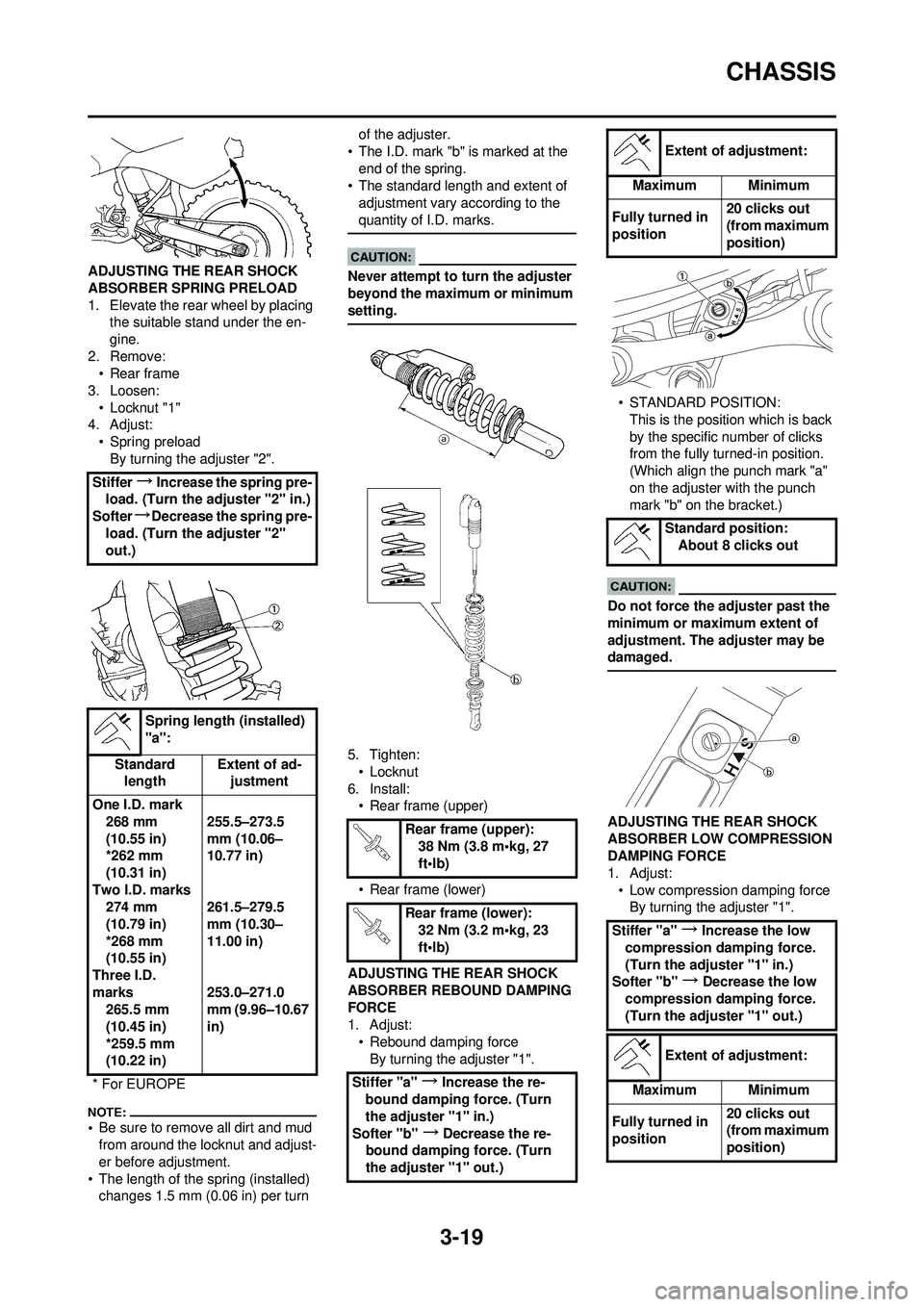
ADJUSTING THE REAR SHOCK
ABSORBER SPRING PRELOAD
1. Elevate the rear wheel by placing the suitable stand under the en-
gine.
2. Remove: • Rear frame
3. Loosen: • Locknut "1"
4. Adjust:
• Spring preloadBy turning the adjuster "2".
•Be sure to remove all dirt and mud
from around the locknut and adjust-
er before adjustment.
• The length of the spring (installed) changes 1.5 mm (0.06 in) per turn of the adjuster.
• The I.D. mark "b" is marked at the end of the spring.
• The standard length and extent of
adjustment vary according to the
quantity of I.D. marks.
Never attempt to turn the adjuster
beyond the maximum or minimum
setting.
5. Tighten:• Locknut
6. Install: • Rear frame (upper)
• Rear frame (lower)
ADJUSTING THE REAR SHOCK
ABSORBER REBOUND DAMPING
FORCE
1. Adjust: • Rebound damping forceBy turning the adjuster "1". • STANDARD POSITION:
This is the position which is back
by the specific number of clicks
from the fully turned-in position.
(Which align the punch mark "a"
on the adjuster with the punch
mark "b" on the bracket.)
Do not force the adjuster past the
minimum or maximum extent of
adjustment. The adjuster may be
damaged.
ADJUSTING THE REAR SHOCK
ABSORBER LOW COMPRESSION
DAMPING FORCE
1. Adjust:• Low compression damping forceBy turning the adjuster "1".
Stiffer
→Increase the spring pre-
load. (Turn the adjuster "2" in.)
Softer
→Decrease the spring pre-
load. (Turn the adjuster "2"
out.)
Spring length (installed)
"a":
Standard length Extent of ad-
justment
One I.D. mark 268 mm
(10.55 in)
*262 mm
(10.31 in)
Two I.D. marks 274 mm
(10.79 in)
*268 mm
(10.55 in)
Three I.D.
marks 265.5 mm
(10.45 in)
*259.5 mm
(10.22 in) 255.5–273.5
mm (10.06–
10.77 in)
261.5–279.5
mm (10.30–
11.00 in)
253.0–271.0
mm (9.96–10.67
in)
* For EUROPE
Rear frame (upper): 38 Nm (3.8 m•kg, 27
ft•lb)
Rear frame (lower): 32 Nm (3.2 m•kg, 23
ft•lb)
Stiffer "a"
→Increase the re-
bound damping force. (Turn
the adjuster "1" in.)
Softer "b"
→Decrease the re-
bound damping force. (Turn
the adjuster "1" out.)
Extent of adjustment:
Maximum Minimum
Fully turned in
position 20 clicks out
(from maximum
position)
Standard position: About 8 clicks out
Stiffer "a"
→Increase the low
compression damping force.
(Turn the adjuster "1" in.)
Softer "b"
→Decrease the low
compression damping force.
(Turn the adjuster "1" out.)
Extent of adjustment:
Maximum Minimum
Fully turned in
position 20 clicks out
(from maximum
position)
Page 66 of 192

3-20
CHASSIS
• STANDARD POSITION:This is the position which is back
by the specific number of clicks
from the fully turned-in position.
(Which align the punch mark "a"
on the adjuster with the punch
mark "b" on the high compression
damping adjuster.)
Do not force the adjuster past the
minimum or maximum extent of
adjustment. The adjuster may be
damaged.
ADJUSTING THE REAR SHOCK
ABSORBER HIGH COMPRESSION
DAMPING FORCE
1. Adjust:• High compression damping force
By turning the adjuster "1".
• STANDARD POSITION: This is the position which is back
by the specific number of turns
from the fully turned-in position.
(Which align the punch mark "a"
on the adjuster with the punch
mark "b" on the adjuster body.)
Do not force the adjuster past the
minimum or maximum extent of
adjustment. The adjuster may be
damaged.
CHECKING THE TIRE PRESSURE
1. Measure:
• Tire pressureOut of specification
→Adjust.
•Check the tire while it is cold.
• Loose bead stoppers allow the tire
to slip off its position on the rim
when the tire pressure is low.
• A tilted tire valve stem indicates that
the tire slips off its position on the
rim.
• If the tire valve stem is found tilted,
the tire is considered to be slipping
off its position. Correct the tire posi-
tion.
CHECKING AND TIGHTENING THE
SPOKES
1. Inspect:• Spokes "1"Bend/damage
→Replace.
Loose spoke
→Retighten.
2. Tighten: •Spokes
Be sure to retighten these spokes be-
fore and after break-in. After a prac-
tice or a race check spokes for
looseness.
CHECKING THE WHEELS
1. Inspect:
• Wheel runoutElevate the wheel and turn it.
Abnormal runout
→ Replace.
2. Inspect: • Bearing free play
Exist play
→Replace.
CHECKING AND ADJUSTING THE
STEERING HEAD
1. Elevate the front wheel by placing a suitable stand under the engine.
2. Check:
• Steering stemGrasp the bottom of the forks and
gently rock the fork assembly
back and forth.
Free play
→Adjust steering head.
Standard position:
About 8 clicks out
Stiffer "a"
→Increase the high
compression damping force.
(Turn the adjuster "1" in.)
Softer "b"
→Decrease the high
compression damping force.
(Turn the adjuster "1" out.)
Extent of adjustment:
Maximum Minimum
Fully turned in
position 2 turns out
(from maximum
position)
Standard position:
About 1-1/2 turns out
Standard tire pressure: 100 kPa (1.0 kgf/cm
2,
15 psi)
Spokes: 3 Nm (0.3 m•kg, 2.2
ft•lb)
Page 85 of 192

4-16
CAMSHAFTS
REMOVING THE CAMSHAFT
1. Remove:• Timing mark accessing screw "1"
• Crankshaft end accessing screw "2"
2. Align: • T.D.C. mark
With align mark.
Checking steps:
a. Turn the crankshaft counterclock- wise with a wrench.
b. Align the T.D.C. mark "a" on the rotor with the align mark "b" on the
crankcase cover when piston is at
T.D.C. on compression stroke.
In order to be sure that the piston is at
Top Dead Center, the punch mark "c"
on the exhaust camshaft and the
punch mark "d" on the intake cam-
shaft must align with the cylinder
head surface, as shown in the illustra-
tion.
3. Remove:• Timing chain tensioner cap bolt
"1"
• Timing chain tensioner "2"
•Gasket 4. Remove:
• Bolt (camshaft cap) "1"
• Camshaft cap "2"
•Clip
Remove the bolts (camshaft cap) in a
crisscross pattern, working from the
outside in.
The bolts (camshaft cap) must be
removed evenly to prevent dam-
age to the cylinder head, cam-
shafts or camshaft caps.
5. Remove:• Exhaust camshaft "1"
• Intake camshaft "2"
Attach a wire "3" to the timing chain to
prevent it from falling into the crank-
case.
CHECKING THE CAMSHAFT
1. Inspect:• Cam lobe
Pitting/scratches/blue discolora-
tion
→Replace.
2. Measure:
• Cam lobe length "a" and "b" Out of specification
→Replace.
3. Measure: • Runout (camshaft)Out of specification
→Replace.
Cam lobes length: Intake "a":30.246–30.346 mm
(1.1908–1.1947 in)
Intake "b":
22.45–22.55 mm
(0.8839–0.8878 in)
22.35 mm (0.8799 in)
Exhaust "a": 30.399–30.499 mm
(1.1968–1.2007 in)
Exhaust "b": 22.45–22.55 mm
(0.8839–0.8878 in)
Runout (camshaft): Less than 0.03 mm
(0.0012 in)
Page 86 of 192

4-17
CAMSHAFTS
4. Measure:• Camshaft-to-cap clearanceOut of specification
→Measure
camshaft outside diameter.
Measurement steps:
a. Install the camshaft onto the cylin-
der head.
b. Position a strip of Plastigauge
®
"1" onto the camshaft.
c. Install the clip, dowel pins and camshaft caps.
• Tighten the bolts (camshaft cap) in a crisscross pattern from innermost
to outer caps.
• Do not turn the camshaft when measuring clearance with the Plas-
tigauge
®.
d. Remove the camshaft caps and measure the width of the Plasti-
gauge
® "1".
5. Measure:• Camshaft outside diameter "a"Out of specification
→Replace
the camshaft.
Within specification
→Replace
camshaft case and camshaft
caps as a set. CHECKING THE CAMSHAFT
SPROCKET
1. Inspect:
• Camshaft sprocket "1"
Wear/damage
→Replace the
camshaft assembly and timing
chain as a set.
CHECKING THE
DECOMPRESSION SYSTEM
1. Check: • Decompression system
Checking steps:
a. Check that the decompression mechanism cam "1" moves
smoothly.
b. Check that the decompression
mechanism cam lever pin "2"
projects from the camshaft.
CHECKING THE TIMING CHAIN
TENSIONER
1. Check:• While pressing the tensioner rod
lightly with fingers, use a thin
screwdriver "1" and wind the ten-
sioner rod up fully clockwise.
• When releasing the screwdriver by pressing lightly with fingers,
make sure that the tensioner rod
will come out smoothly.
• If not, replace the tensioner as- sembly. INSTALLING THE CAMSHAFT
1. Install:
• Exhaust camshaft "1"
• Intake camshaft "2"
Installation steps:
a. Turn the crankshaft counterclock- wise with a wrench.
• Apply the molybdenum disulfide oil
on the camshafts.
• Apply the engine oil on the decom- pression system.
• Squeezing the decompression le- ver allows the crankshaft to be
turned easily.
b. Align the T.D.C. mark "a" on the rotor with the align mark "b" on the
crankcase cover when piston is at
T.D.C. on compression stroke.
Camshaft-to-cap clear-
ance:
0.028–0.062 mm
(0.0011–0.0024 in)
in)
Bolt (camshaft cap): 10 Nm (1.0 m•kg, 7.2
ft•lb)
Camshaft outside diame-
ter: 21.959–21.972 mm
(0.8645–0.8650 in)