2008 YAMAHA YZ250F fuel
[x] Cancel search: fuelPage 51 of 192

3-5
PRE-OPERATION INSPECTION AND MAINTENANCE
PRE-OPERATION INSPECTION AND MAINTENANCE
Before riding for break-in operation, practice or a race, make sure the machine is in good operating condition.
Before using this machine, check the following points.
GENERAL INSPECTION AND MAINTENANCEItem RoutinePage
Coolant Check that coolant is filled up to the radiator cap. Check the cool-
ing system for leakage. P.3-6 – 7
Fuel Check that a fresh gasoline is filled in the fuel tank. Check the fuel
line for leakage. P.1-8 – 9
Engine oil Check that the oil level is correct. Check the crankcase and oil line
for leakage. P.3-8 – 10
Gear shifter and clutch Check that gears can be shifted correctly in order and that the
clutch operates smoothly. P.3-7
Throttle grip/Housing Check that the throttle grip operation and free play are correctly
adjusted. Lubricate the throttle grip and housing, if necessary. P.3-7 – 8
Brakes Check the play of front brake and effect of front and rear brake. P.3-14 – 16
Drive chain Check drive chain slack and alignment. Check that the drive chain
is lubricated properly. P.3-17
Wheels Check for excessive wear and tire pressure. Check for loose
spokes and have no excessive play. P.3-20
Steering Check that the handlebar can be turned smoothly and have no ex-
cessive play. P.3-20 – 21
Front forks and rear shock
absorber Check that they operate smoothly and there is no oil leakage.
P.3-18 – 20
Cables (wires) Check that the clutch and throttle cables move smoothly. Check
that they are not caught when the handlebars are turned or when
the front forks travel up and down.
—
Exhaust pipe Check that the exhaust pipe is tightly mounted and has no cracks. P.4-3 – 4
Rear wheel sprocket Check that the rear wheel sprocket tightening bolt is not loose. P.3-16 – 17
Lubrication Check for smooth operation. Lubricate if necessary. P.3-22
Bolts and nuts Check the chassis and engine for loose bolts and nuts. P.1-11
Lead connectors Check that the CDI magneto, CDI unit, and ignition coil are con-
nected tightly. P.1-3
Settings Is the machine set suitably for the condition of the racing course
and weather or by taking into account the results of test runs be-
fore racing? Are inspection and maintenance completely done?
P.7-1 – 10
Page 56 of 192

3-10
ENGINE
• Oil hose clamp
9. Install: • Copper washer
• Oil filter element drain bolt
• Crankcase oil drain bolt
• Oil tank drain bolt
• Lower engine guard
10. Fill: • Engine oil
11. Check: • Oil leakage
12. Install: • Oil filler cap
• Washer (oil tank) • Bolt (oil tank)
13. Check: • Engine oil level
CHECKING THE OIL PRESSURE
1. Check: • Oil pressure
Checking steps:
a. Slightly loosen the oil pressure check bolt "1".
b. Start the engine and keep it idling until oil starts to seep from the oil
pressure check bolt. If no oil
comes out after one minute, turn
the engine off so it will not seize.
c. Check oil passages and oil pump for damage or leakage.
d. Start the engine after solving the
problem(s) and recheck the oil
pressure.
e. Tighten the oil pressure check
bolt.
ADJUSTING THE PILOT SCREW
1. Adjust:• Pilot screw "1"
Adjustment steps:
To optimize the fuel flow at a smaller
throttle opening, each machine's pilot
screw has been individually set at the
factory. Before adjusting the pilot
screw, turn it in fully and count the
number of turns. Record this number
as the factory-set number of turns
out.
a. Turn in the pilot screw until it is lightly seated.
b. Turn out the pilot screw by the factory-set number of turns.
ADJUSTING THE ENGINE IDLING
SPEED
1. Start the engine and thoroughly warm it up.
2. Adjust: • Engine idling speed
Adjustment steps:
a. Adjust the pilot screw. Refer to "ADJUSTING THE PI-
LOT SCREW" section.
b. Turn the throttle stop screw "1"
until the specified engine idling
speed.
Using a digital engine tachometer for
idle speed adjustment, detect the en-
gine idling speed by bringing the
sensing element "c" of the engine ta-
chometer close to the ignition coil "2".
Oil hose clamp:2 Nm (0.2 m•kg, 1.4
ft•lb)
Oil filter element drain
bolt: 10 Nm (1.0 m•kg, 7.2
ft•lb)
Crankcase oil drain bolt: 20 Nm (2.0 m•kg, 14
ft•lb)
Oil tank drain bolt: 18 Nm (1.8 m•kg, 13
ft•lb)
Lower engine guard: 10 Nm (1.0 m•kg, 7.2
ft•lb)
Oil quantity: Periodic oil change:1.05 L (0.92 Imp qt,
1.11 US qt)
With oil filter replace-
ment: 1.15 L (1.01 Imp qt,
1.22 US qt)
Total amount:
1.30 L (1.14 Imp qt,
1.37 US qt)Bolt (oil tank): 7 Nm (0.7 m•kg, 5.1
ft•lb)
Oil pressure check bolt: 10 Nm (1.0 m•kg, 7.2
ft•lb)
Pilot screw (example): 2-3/8 turns out
To increase idle speed→Turn the
throttle stop screw "1" in "a".
To decrease idle speed
→Turn
the throttle stop screw "1" out
"b".
Engine idling speed:1,900–2,100 r/min
Page 57 of 192

3-11
ENGINE
ADJUSTING THE VALVE
CLEARANCE
•The valve clearance should be ad-
justed when the engine is cool to
the touch.
• The piston must be at Top Dead Center (T.D.C.) on compression
stroke to check or adjust the valve
clearance.
1. Remove:• Seat
• Fuel tankRefer to "SEAT, FUEL TANK
AND SIDE COVERS" section in
the CHAPTER 4.
2. Remove: • Spark plug
• Cylinder head coverRefer to "CAMSHAFTS" section
in the CHAPTER 4.
3. Remove:
• Timing mark accessing screw "1"
• Crankshaft end accessing screw "2"
• O-ring
4. Check: • Valve clearance
Out of specification
→Adjust.
Checking steps:
a. Turn the crankshaft counterclock- wise with a wrench.
b. Align the T.D.C. mark "a" on the rotor with the align mark "b" on the
crankcase cover when piston is at
T.D.C. on compression stroke.
In order to be sure that the piston is at
Top Dead Center, the punch mark "c"
on the exhaust camshaft and the
punch mark "d" on the intake cam-
shaft must align with the cylinder
head surface, as shown in the illustra-
tion.
c. Measure the valve clearance "e"
using a feeler gauge "1".
Record the measured reading if the
clearance is incorrect.
5. Adjust:• Valve clearance
Adjustment steps:
a. Remove the camshaft (intake and exhaust).
Refer to "CAMSHAFTS" section
in the CHAPTER 4.
b. Remove the valve lifters "1" and the pads "2".
•Place a rag in the timing chain
space to prevent pads from falling
into the crankcase.
• Identity each valve lifter and pad
position very carefully so that they
can be reinstalled in their original
place.
c. Select the proper pad using the pad selecting table.
The thickness "a" of each pad is indi-
cated in hundredths of millimeters on
the pad upper surface.
d. Round off the last digit of the in-stalled pad number to the nearest
increment.
EXAMPLE:
Installed pad number = 148
Rounded off value = 150
Pads can only be selected in 0.05
mm increments.
e. Locate the rounded-off value and the measured valve clearance in
the chart "PAD SELECTION TA-
BLE". The field where these two
coordinates intersect shows the
new pad number to use.
Valve clearance (cold):
Intake valve:0.10–0.15 mm
(0.0039–0.0059 in)
Exhaust valve: 0.17–0.22 mm
(0.0067–0.0087 in)
Pad range Pad Availabili-
ty: 25 incre-
ments
No.
120– No.
240 1.20
mm– 2.40 mm Pads are avail-
able in 0.05 mm increments
Last digit of pad number Rounded valve
0, 1 or 2 0
4, 5 or 6 5
8 or 9 10
Page 67 of 192
3-21
CHASSIS
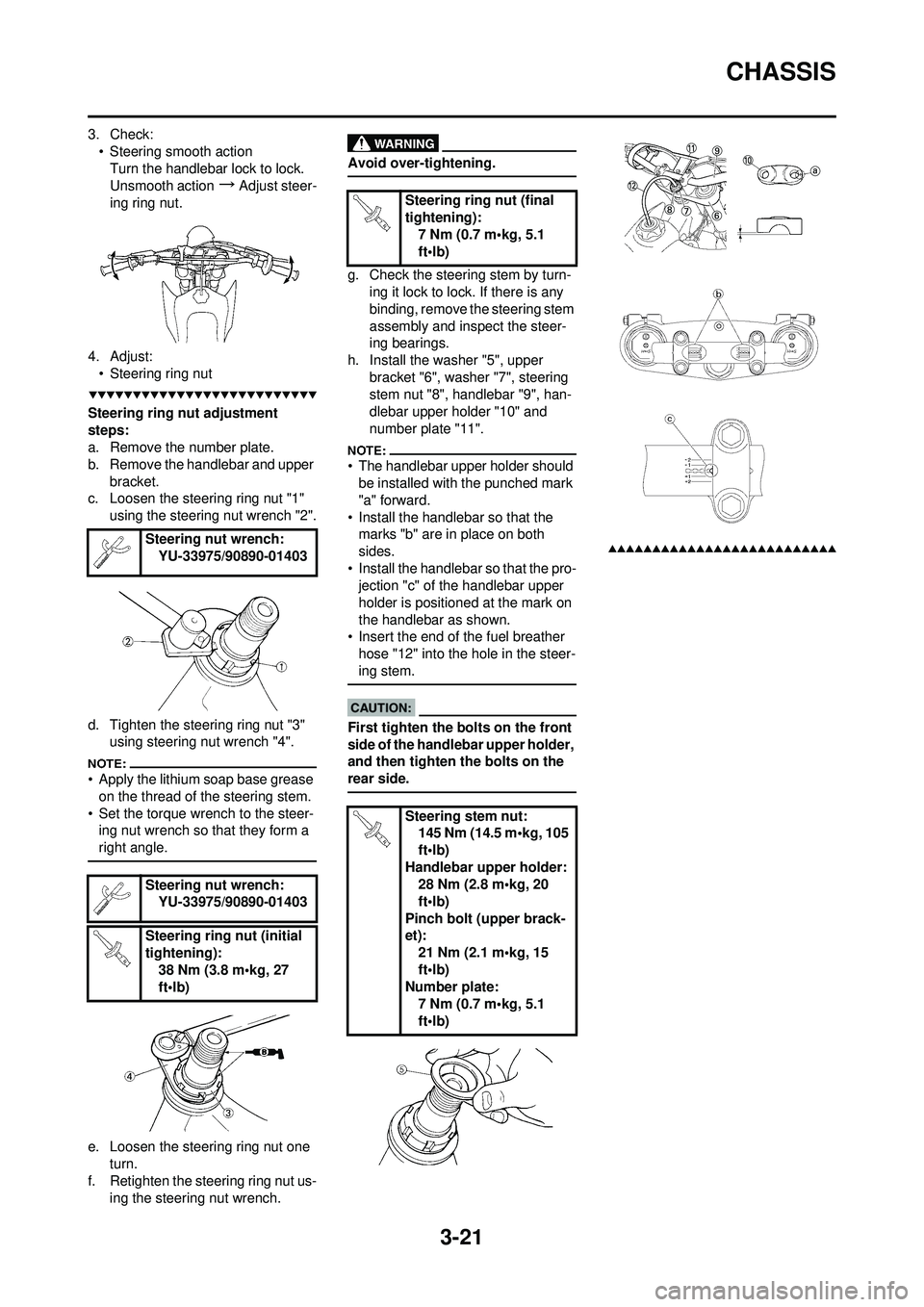
3. Check:• Steering smooth actionTurn the handlebar lock to lock.
Unsmooth action
→Adjust steer-
ing ring nut.
4. Adjust: • Steering ring nut
Steering ring nut adjustment
steps:
a. Remove the number plate.
b. Remove the handlebar and upper
bracket.
c. Loosen the steering ring nut "1"
using the steering nut wrench "2".
d. Tighten the steering ring nut "3" using steering nut wrench "4".
• Apply the lithium soap base grease
on the thread of the steering stem.
• Set the torque wrench to the steer- ing nut wrench so that they form a
right angle.
e. Loosen the steering ring nut one
turn.
f. Retighten the steering ring nut us- ing the steering nut wrench.
Avoid over-tightening.
g. Check the steering stem by turn-ing it lock to lock. If there is any
binding, remove the steering stem
assembly and inspect the steer-
ing bearings.
h. Install the washer "5", upper bracket "6", washer "7", steering
stem nut "8", handlebar "9", han-
dlebar upper holder "10" and
number plate "11".
• The handlebar upper holder should be installed with the punched mark
"a" forward.
• Install the handlebar so that the marks "b" are in place on both
sides.
• Install the handlebar so that the pro- jection "c" of the handlebar upper
holder is positioned at the mark on
the handlebar as shown.
• Insert the end of the fuel breather
hose "12" into the hole in the steer-
ing stem.
First tighten the bolts on the front
side of the handlebar upper holder,
and then tighten the bolts on the
rear side.
Steering nut wrench: YU-33975/90890-01403
Steering nut wrench: YU-33975/90890-01403
Steering ring nut (initial
tightening): 38 Nm (3.8 m•kg, 27
ft•lb)
Steering ring nut (final
tightening):7 Nm (0.7 m•kg, 5.1
ft•lb)
Steering stem nut: 145 Nm (14.5 m•kg, 105
ft•lb)
Handlebar upper holder: 28 Nm (2.8 m•kg, 20
ft•lb)
Pinch bolt (upper brack-
et): 21 Nm (2.1 m•kg, 15
ft•lb)
Number plate:
7 Nm (0.7 m•kg, 5.1
ft•lb)
Page 70 of 192

4-1
SEAT, FUEL TANK AND SIDE COVERS
ENGINE
SEAT, FUEL TANK AND SIDE COVERS
REMOVING THE SEAT, FUEL TANK AND SIDE COVERSOrder Part name Q'ty Remarks Turn the fuel cock to "OFF".
Disconnect the fuel hose.
1 Seat 1
2 Air scoop (left and right) 2
3 Bolt (fuel tank) 2
4 Fuel tank 1
5 Left side cover 1 Refer to removal section.
6 Right side cover 1 Refer to removal section.
7 Number plate 1 Refer to removal section.
Page 71 of 192
4-2
SEAT, FUEL TANK AND SIDE COVERS
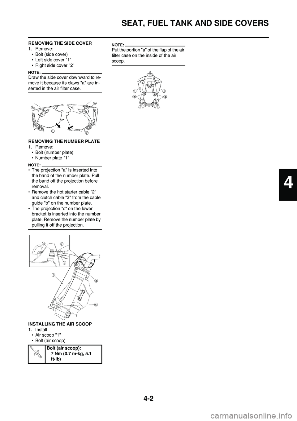
REMOVING THE SIDE COVER
1. Remove:• Bolt (side cover)
• Left side cover "1"
• Right side cover "2"
Draw the side cover downward to re-
move it because its claws "a" are in-
serted in the air filter case.
REMOVING THE NUMBER PLATE
1. Remove:• Bolt (number plate)
• Number plate "1"
• The projection "a" is inserted into
the band of the number plate. Pull
the band off the projection before
removal.
• Remove the hot starter cable "2" and clutch cable "3" from the cable
guide "b" on the number plate.
• The projection "c" on the lower bracket is inserted into the number
plate. Remove the number plate by
pulling it off the projection.
INSTALLING THE AIR SCOOP
1. Install• Air scoop "1"
• Bolt (air scoop)
Put the portion "a" of the flap of the air
filter case on the inside of the air
scoop.
Bolt (air scoop):
7 Nm (0.7 m•kg, 5.1
ft•lb)
4
Page 72 of 192
4-3
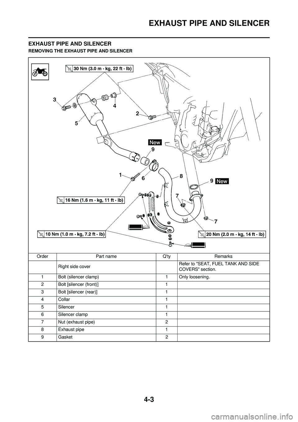
EXHAUST PIPE AND SILENCER
EXHAUST PIPE AND SILENCER
REMOVING THE EXHAUST PIPE AND SILENCEROrder Part name Q'ty Remarks Right side cover Refer to "SEAT, FUEL TANK AND SIDE
COVERS" section.
1 Bolt (silencer clamp) 1 Only loosening.
2 Bolt [silencer (front)] 1
3 Bolt [silencer (rear)] 1
4Collar 1
5 Silencer 1
6 Silencer clamp 1
7 Nut (exhaust pipe) 2
8 Exhaust pipe 1
9Gasket 2
Page 74 of 192
4-5
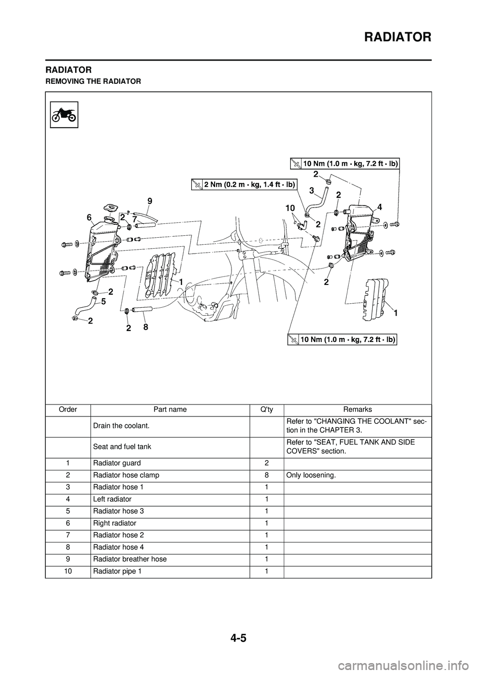
RADIATOR
RADIATOR
REMOVING THE RADIATOROrder Part name Q'ty Remarks Drain the coolant. Refer to "CHANGING THE COOLANT" sec-
tion in the CHAPTER 3.
Seat and fuel tank Refer to "SEAT, FUEL TANK AND SIDE
COVERS" section.
1 Radiator guard 2
2 Radiator hose clamp 8 Only loosening.
3 Radiator hose 1 1
4 Left radiator 1
5 Radiator hose 3 1
6 Right radiator 1
7 Radiator hose 2 1
8 Radiator hose 4 1
9 Radiator breather hose 1
10 Radiator pipe 1 1