2008 YAMAHA YZ250F torque
[x] Cancel search: torquePage 37 of 192

2-15
TIGHTENING TORQUES
GENERAL TORQUE
SPECIFICATIONS
This chart specifies torque for stan-
dard fasteners with standard I.S.O.
pitch threads. Torque specifications
for special components or assem-
blies are included in the applicable
sections of this book. To avoid
warpage, tighten multi-fastener as-
semblies in a crisscross fashion, in
progressive stages, until full torque is
reached. Unless otherwise specified,
torque specifications call for clean,
dry threads. Components should be
at room temperature.A. Distance between flats
B. Outside thread diameter
DEFINITION OF UNITS
A
(Nut) B
(Bolt
) TORQUE SPECIFI-
CATION
Nm m•kg ft•lb
10
mm 6 mm 6 0.6 4.3
12
mm 8 mm 15 1.5 11
14
mm 10
mm 30 3.0 22
17
mm 12
mm 55 5.5 40
19
mm 14
mm 85 8.5 61
22
mm 16
mm 130 13 94
Unit
Read Definition Measure
mm
millimeter 10-3 meterLength
cmcentimeter 10-2 meterLength
kgkilogram 103 gramWeight
NNewton 1 kg × m/sec2Force
NmNewton meterN × mTorque
m•kgMeter kilogram m × kgTorque
PaPascal N/m2Pressure
N/mmNewton per millimeter N/mm Spring rate
LLiter—Volume or capacity
cm3Cubic centimeter —Volume or capacity
r/minRevolution per minute —Engine speed
Page 67 of 192

3-21
CHASSIS
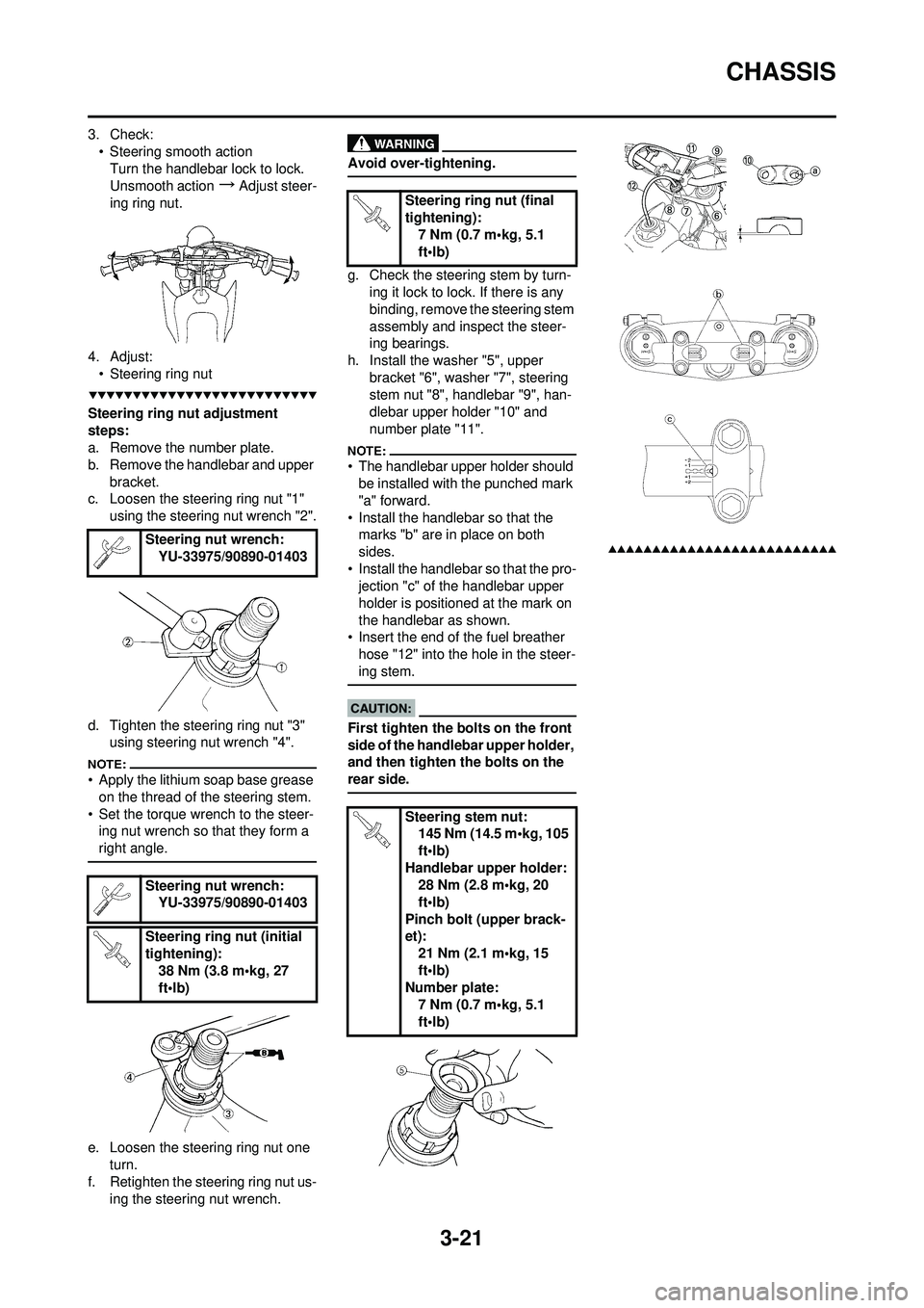
3. Check:• Steering smooth actionTurn the handlebar lock to lock.
Unsmooth action
→Adjust steer-
ing ring nut.
4. Adjust: • Steering ring nut
Steering ring nut adjustment
steps:
a. Remove the number plate.
b. Remove the handlebar and upper
bracket.
c. Loosen the steering ring nut "1"
using the steering nut wrench "2".
d. Tighten the steering ring nut "3" using steering nut wrench "4".
• Apply the lithium soap base grease
on the thread of the steering stem.
• Set the torque wrench to the steer- ing nut wrench so that they form a
right angle.
e. Loosen the steering ring nut one
turn.
f. Retighten the steering ring nut us- ing the steering nut wrench.
Avoid over-tightening.
g. Check the steering stem by turn-ing it lock to lock. If there is any
binding, remove the steering stem
assembly and inspect the steer-
ing bearings.
h. Install the washer "5", upper bracket "6", washer "7", steering
stem nut "8", handlebar "9", han-
dlebar upper holder "10" and
number plate "11".
• The handlebar upper holder should be installed with the punched mark
"a" forward.
• Install the handlebar so that the marks "b" are in place on both
sides.
• Install the handlebar so that the pro- jection "c" of the handlebar upper
holder is positioned at the mark on
the handlebar as shown.
• Insert the end of the fuel breather
hose "12" into the hole in the steer-
ing stem.
First tighten the bolts on the front
side of the handlebar upper holder,
and then tighten the bolts on the
rear side.
Steering nut wrench: YU-33975/90890-01403
Steering nut wrench: YU-33975/90890-01403
Steering ring nut (initial
tightening): 38 Nm (3.8 m•kg, 27
ft•lb)
Steering ring nut (final
tightening):7 Nm (0.7 m•kg, 5.1
ft•lb)
Steering stem nut: 145 Nm (14.5 m•kg, 105
ft•lb)
Handlebar upper holder: 28 Nm (2.8 m•kg, 20
ft•lb)
Pinch bolt (upper brack-
et): 21 Nm (2.1 m•kg, 15
ft•lb)
Number plate:
7 Nm (0.7 m•kg, 5.1
ft•lb)
Page 87 of 192

4-18
CAMSHAFTS
c. Fit the timing chain "3" onto both camshaft sprockets and install the
camshafts on the cylinder head.
The camshafts should be installed
onto the cylinder head so that the
punch mark "c" on the exhaust cam-
shaft and the punch mark "d" on the
intake camshaft must align with the
cylinder head surface, as shown in
the illustration.
Do not turn the crankshaft during
the camshaft installation. Damage
or improper valve timing will re-
sult.
d. Install the clips, camshaft caps "4" and bolts (camshaft cap) "5".
• Before removing the clips, cover the cylinder head with a clean rag to
prevent the clips from into the cylin-
der head cavity.
• Apply the molybdenum disulfide oil
on the thread of the bolts (camshaft
cap).
• Tighten the bolts to the specified
torque in two or three steps in the
proper tightening sequence as
shown.
The bolts (camshaft cap) must be
tightened evenly, or damage to the
cylinder head, camshaft caps, and
camshaft will result.
2. Install:• Timing chain tensioner
Installation steps:
a. While pressing the tensioner rod
lightly with fingers, use a thin
screwdriver and wind the tension-
er rod up fully clockwise.
b. With the rod fully wound and the chain tensioner UP mark "a" fac-
ing upward, install the gasket "1"
and the timing chain tensioner "2",
and tighten the bolt "3" to the
specified torque.
c. Release the screwdriver, check the tensioner rod to come out and
tighten the gasket "4" and the cap
bolt "5" to the specified torque.
3. Turn:
• CrankshaftCounterclockwise several turns.
4. Check: • Rotor T.D.C. markAlign with the crankcase align
mark.
• Camshaft match marks Align with the cylinder head sur-
face.
Out of alignment
→Adjust. 5. Install:
• Timing mark accessing screw "1"
• Crankshaft end accessing screw "2"
6. Install: • Timing chain guide (top side) "1"
• Cylinder head cover gasket "2"
• Cylinder head cover "3"
• Bolt (cylinder head cover) "4"
Apply the sealant on the cylinder
head cover gasket.
7. Install:• Cylinder head breather hose
• Spark plug
Bolt (camshaft cap):
10 Nm (1.0 m•kg, 7.2
ft•lb)
Bolt (timing chain ten-
sioner):10 Nm (1.0 m•kg, 7.2
ft•lb)
Tensioner cap bolt: 7 Nm (0.7 m•kg, 5.1
ft•lb)
Bolt (cylinder head cov-
er):
10 Nm (1.0 m•kg, 7.2
ft•lb)
YAMAHA Bond No. 1215
(ThreeBond
® No. 1215):
90890-85505
Spark plug: 13 Nm (1.3 m•kg, 9.4
ft•lb)
Page 152 of 192

5-20
FRONT FORK
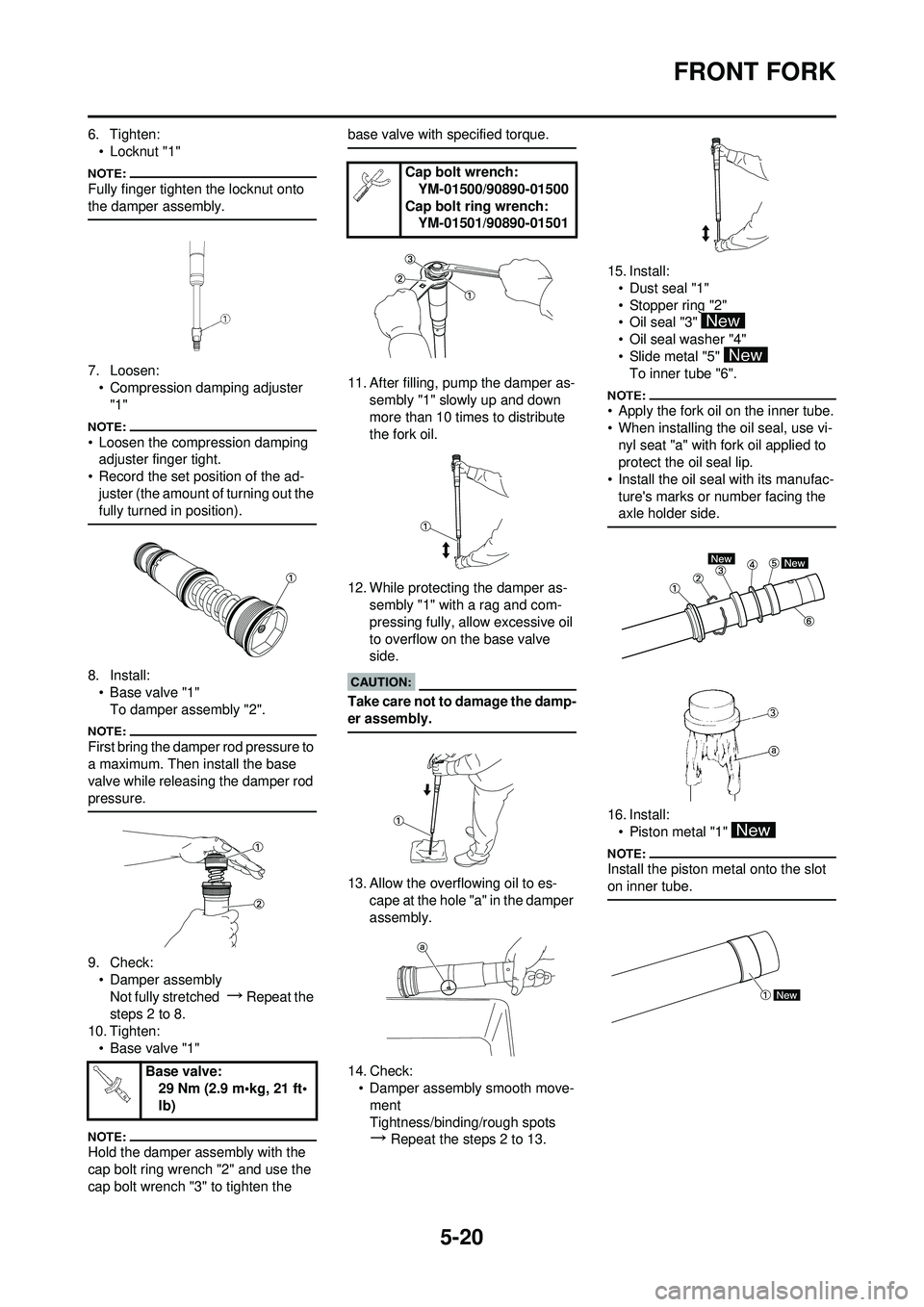
6. Tighten:• Locknut "1"
Fully finger tighten the locknut onto
the damper assembly.
7. Loosen:• Compression damping adjuster "1"
• Loosen the compression damping adjuster finger tight.
• Record the set position of the ad- juster (the amount of turning out the
fully turned in position).
8. Install:• Base valve "1"To damper assembly "2".
First bring the damper rod pressure to
a maximum. Then install the base
valve while releasing the damper rod
pressure.
9. Check:• Damper assemblyNot fully stretched
→ Repeat the
steps 2 to 8.
10. Tighten: • Base valve "1"
Hold the damper assembly with the
cap bolt ring wrench "2" and use the
cap bolt wrench "3" to tighten the base valve with specified torque.
11. After filling, pump the damper as-
sembly "1" slowly up and down
more than 10 times to distribute
the fork oil.
12. While protecting the damper as- sembly "1" with a rag and com-
pressing fully, allow excessive oil
to overflow on the base valve
side.
Take care not to damage the damp-
er assembly.
13. Allow the overflowing oil to es-
cape at the hole "a" in the damper
assembly.
14. Check: • Damper assembly smooth move-
ment
Tightness/binding/rough spots
→
Repeat the steps 2 to 13. 15. Install:
• Dust seal "1"
• Stopper ring "2"
•Oil seal "3"
• Oil seal washer "4"
• Slide metal "5" To inner tube "6".
• Apply the fork oil on the inner tube.
• When installing the oil seal, use vi-
nyl seat "a" with fork oil applied to
protect the oil seal lip.
• Install the oil seal with its manufac- ture's marks or number facing the
axle holder side.
16. Install:• Piston metal "1"
Install the piston metal onto the slot
on inner tube.
Base valve: 29 Nm (2.9 m•kg, 21 ft•
lb)
Cap bolt wrench:
YM-01500/90890-01500
Cap bolt ring wrench: YM-01501/90890-01501
Page 154 of 192

5-22
FRONT FORK
28. Inspect:• Gap "a" between the adjuster "1" and locknut "2".
Out of specification
→ Retighten
and readjust the locknut.
If the adjuster is installed out of spec-
ification, proper damping force can-
not be obtained.
29. Tighten: • Adjuster (locknut) "1"
Hold the locknut "2" and tighten the
adjuster with specified torque.
30. Install:•Adjuster "1"
To inner tube. 31. Fill:
• Front fork oil "1"From outer tube top.
Never fail to make the oil amount
adjustment between the maximum
and minimum amount and always
adjust each front fork to the same
setting. Uneven adjustment can
cause poor handling and loss of
stability.
• Be sure to use recommended fork oil. If other oils are used,
they may have an excessively ad-
verse effect on the front fork per-
formance.
• Never allow foreign materials to enter the front fork.
32. Install:
• Damper assembly "1"To outer tube.
Temporarily tighten the damper as-
sembly.
33. Install:
• Protector guide "1" INSTALLING THE FRONT FORK
1. Install:
• Front fork "1"
• Temporarily tighten the pinch bolts (lower bracket).
• Do not tighten the pinch bolts (up- per bracket) yet.
2. Tighten:• Damper assembly "1"
Use the cap bolt ring wrench "2" to
tighten the damper assembly with
specified torque.
3. Adjust:• Front fork top end "a"
Gap "a" between the ad-
juster and locknut:
0.5–1.0 mm (0.02–0.04
in)
Adjuster (locknut): 29 Nm (2.9 m•kg, 21
ft•lb)
Adjuster: 55 Nm (5.5 m•kg, 40
ft•lb)
Recommended oil:Suspension oil "S1"
Standard oil amount: 330 cm
3 (11.6 Imp oz,
11.2 US oz)
Extent of adjustment: 300–375 cm
3
(10.6–13.2 Imp oz,10.1–
12.7 US oz)
Damper assembly:30 Nm (3.0 m•kg, 22
ft•lb)
Cap bolt ring wrench: YM-01501/90890-01501
Front fork top end (stan-
dard) "a": 5 mm (0.20 in)
Page 155 of 192

5-23
FRONT FORK
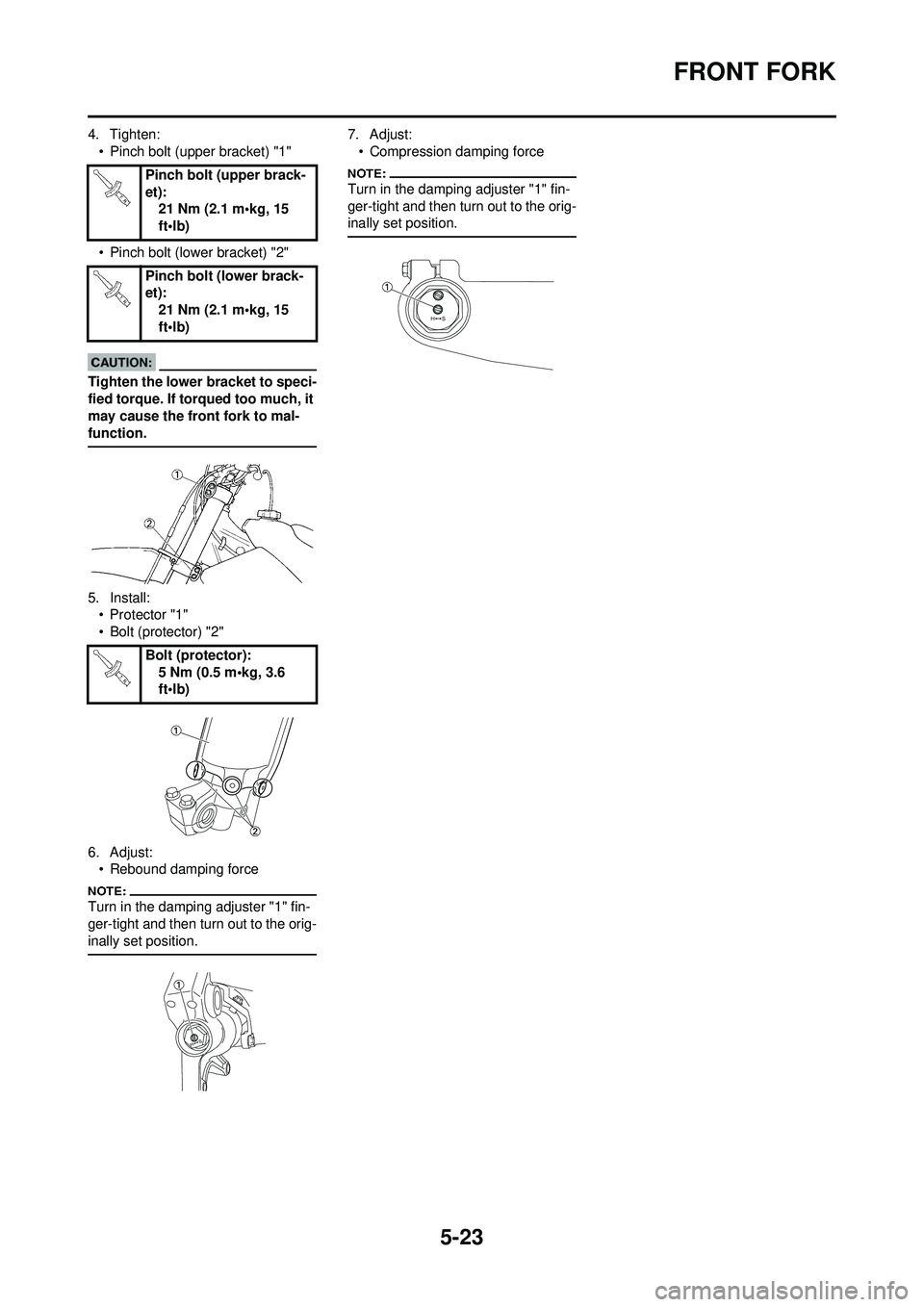
4. Tighten:• Pinch bolt (upper bracket) "1"
• Pinch bolt (lower bracket) "2"
Tighten the lower bracket to speci-
fied torque. If torqued too much, it
may cause the front fork to mal-
function.
5. Install:• Protector "1"
• Bolt (protector) "2"
6. Adjust: • Rebound damping force
Turn in the damping adjuster "1" fin-
ger-tight and then turn out to the orig-
inally set position.
7. Adjust:
• Compression damping force
Turn in the damping adjuster "1" fin-
ger-tight and then turn out to the orig-
inally set position.Pinch bolt (upper brack-
et): 21 Nm (2.1 m•kg, 15
ft•lb)
Pinch bolt (lower brack-
et): 21 Nm (2.1 m•kg, 15
ft•lb)
Bolt (protector): 5 Nm (0.5 m•kg, 3.6
ft•lb)
Page 163 of 192

5-31
STEERING
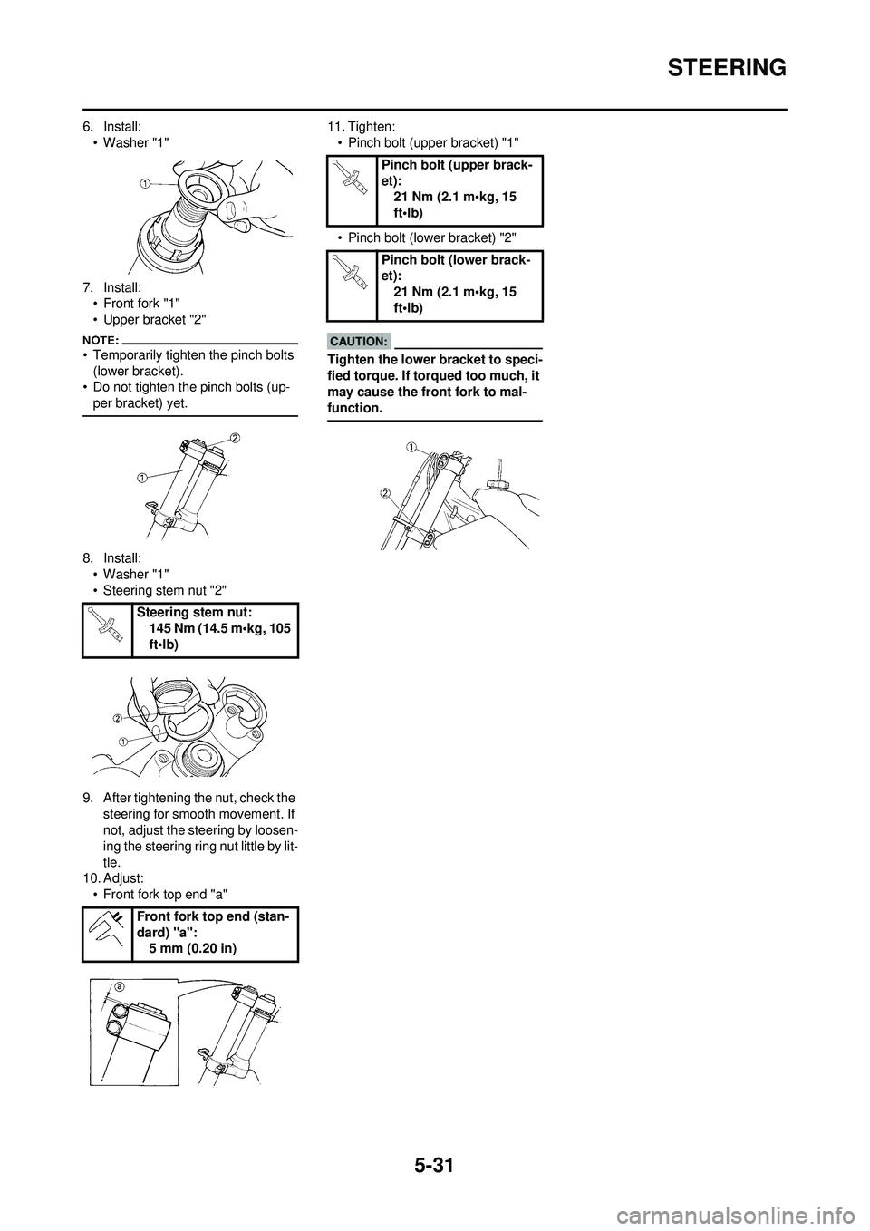
6. Install:• Washer "1"
7. Install: • Front fork "1"
• Upper bracket "2"
• Temporarily tighten the pinch bolts
(lower bracket).
• Do not tighten the pinch bolts (up-
per bracket) yet.
8. Install:• Washer "1"
• Steering stem nut "2"
9. After tightening the nut, check the steering for smooth movement. If
not, adjust the steering by loosen-
ing the steering ring nut little by lit-
tle.
10. Adjust:
• Front fork top end "a" 11. Tighten:
• Pinch bolt (upper bracket) "1"
• Pinch bolt (lower bracket) "2"
Tighten the lower bracket to speci-
fied torque. If torqued too much, it
may cause the front fork to mal-
function.
Steering stem nut: 145 Nm (14.5 m•kg, 105
ft•lb)
Front fork top end (stan-
dard) "a": 5 mm (0.20 in)
Pinch bolt (upper brack-
et):21 Nm (2.1 m•kg, 15
ft•lb)
Pinch bolt (lower brack-
et): 21 Nm (2.1 m•kg, 15
ft•lb)
Page 189 of 192

7-9
CHASSIS
SUSPENSION SETTING (FRONT FORK)
• If any of the following symptoms is experienced with the standard position as the base, make resetting by reference to the adjustment procedure given in the same chart.
• Before any change, set the rear shock absorber sunken length to the standard figure 90–100 mm (3.5–3.9 in).
Symptom Section
Check Adjust
Jump Large
gap Medi-
um
gap Small
gap
Stiff over entire
range
○○○
Compression damping Turn adjuster counterclockwise (about 2 clicks) to decrease damping.
Oil amount Decrease oil amount by about 5–10 cm
3 (0.2–0.4
Imp oz, 0.2–0.3 US oz).
Spring Replace with soft spring.
Unsmooth move-
ment over entire
range
○○○○
Outer tube Check for any bends, dents, and other noticeable
scars, etc. If any, replace affected parts.
Inner tube
Slide metal Replace with a new one for extended use.
Piston metal Replace with a new one for extended use.
Under bracket tighten-
ing torque Retighten to specified torque.
Poor initial move-
ment
○
Rebound damping Turn adjuster counterclockwise (about 2 clicks) to decrease damping.
Oil seal Apply grease in oil seal wall.
Soft over entire
range, bottoming
out
○○
Compression damping Turn adjuster clockwise (about 2 clicks) to in- crease damping.
Oil amount Increase oil amount by about 5–10 cm
3 (0.2–0.4
Imp oz, 0.2–0.3 US oz).
Spring Replace with stiff spring.
Stiff toward stroke
end
○Oil amount Decrease oil amount by about 5 cm3 (0.2 Imp
oz,0.2 US oz).
Soft toward stroke
end, bottoming out
○Oil amount Increase oil amount by about 5 cm3 (0.2 Imp
oz,0.2 US oz).
Stiff initial move-
ment
○○○○Compression damping Turn adjuster counterclockwise (about 2 clicks) to
decrease damping.
Low front, tending to
lower front posture
○○
Compression damping Turn adjuster clockwise (about 2 clicks) to in- crease damping.
Rebound damping Turn adjuster counterclockwise (about 2 clicks) to decrease damping.
Balance with rear end Set sunken length for 95–100 mm (3.7–3.9 in) when one passenger is astride seat (lower rear
posture).
Oil amount Increase oil amount by about 5 cm
3 (0.2 Imp oz,
0.2 US oz).
"Obtrusive" front,
tending to upper
front posture
○○
Compression damping Turn adjuster counterclockwise (about 2 clicks) to decrease damping.
Balance with rear end Set sunken length for 90–95 mm (3.5–3.7 in) when one passenger is astride seat (upper rear
posture).
Spring Replace with soft spring.
Oil amount Decrease oil amount by about 5–10 cm
3 (0.2–0.4
Imp oz, 0.2–0.3 US oz).