Page 17 of 88

INSTRUMENT AND CONTROL FUNCTIONS
3-3
3 To lock the steering
1. Turn the handlebars all the way to
the left.
2. Push the key in from the “OFF” po-
sition, and then turn it to “LOCK”
while still pushing it.
3. Remove the key.To unlock the steering
Push the key in, and then turn it to
“OFF” while still pushing it.
WARNING
EWA10060
Never turn the key to “OFF” or
“LOCK” while the vehicle is moving,
otherwise the electrical systems will
be switched off, which may result in
loss of control or an accident. Make
sure that the vehicle is stopped be-
fore turning the key to “OFF” or“LOCK”.
EAU34341
(Parking)
The steering is locked, and the taillight,
license plate light and auxiliary light are
on. The hazard lights and turn signal
lights can be turned on, but all other
electrical systems are off. The key can
be removed.
The steering must be locked before the
key can be turned to“”.
CAUTION:
ECA11020
Do not use the parking position for
an extended length of time, other-wise the battery may discharge.
1. Push.
2. Turn.
1. Push.
2. Turn.
U11CE1E0.book Page 3 Friday, August 31, 2007 1:25 PM
Page 18 of 88

INSTRUMENT AND CONTROL FUNCTIONS
3-4
3
EAU11003
Indicator and warning lights
EAU11020
Turn signal indicator light“”
This indicator light flashes when the
turn signal switch is pushed to the left or
right.
EAU11060
Neutral indicator light“”
This indicator light comes on when the
transmission is in the neutral position.
EAU11080
High beam indicator light“”
This indicator light comes on when the
high beam of the headlight is switched
on.
EAU11250
Oil level warning light“”
This warning light comes on when the
engine oil level is low.
The electrical circuit of the warning light
can be checked by turning the key to
“ON”.
If the warning light does not come on
for a few seconds, then go off, have a
Yamaha dealer check the electrical cir-
cuit.NOTE:�
Even if the oil level is sufficient, the
warning light may flicker when
riding on a slope or during sudden
acceleration or deceleration, but
this is not a malfunction.
�
This model is also equipped with a
self-diagnosis device for the oil
level detection circuit. If the oil lev-
el detection circuit is defective, the
following cycle will be repeated un-
til the malfunction is corrected: Theoil level warning light will flash ten
times, then go off for 2.5 seconds.
If this occurs, have a Yamaha
dealer check the vehicle.
EAU42740
Fuel level warning light“”
This warning light comes on when the
fuel level drops below approximately
3.7 L (0.98 US gal) (0.81 Imp.gal).
When this occurs, refuel as soon as
possible.
The electrical circuit of the warning light
can be checked by turning the key to
“ON”.
If the warning light does not come on
for a few seconds, and then go off,
have a Yamaha dealer check the elec-
trical circuit.NOTE:�
The vehicle must be on a level sur-
face and positioned upright, other-
wise the fuel level warning light
may not come on and go off at the
appropriate times.
�
This model is also equipped with a
self-diagnosis device for the fuel
level detection circuit. If the fuel
1. Neutral indicator light“”
2. Coolant temperature warning light“”
3. Engine trouble warning light“”
4. High beam indicator light“”
5. Turn signal indicator light“”
6. Oil level warning light“”
7. Fuel level warning light“”
8. Immobilizer system indicator lightU11CE1E0.book Page 4 Friday, August 31, 2007 1:25 PM
Page 19 of 88

INSTRUMENT AND CONTROL FUNCTIONS
3-5
3 level detection circuit is defective,
the following cycle will be repeated
until the malfunction is corrected:
The fuel level warning light will
flash eight times, and then go off
for 3.0 seconds. If this occurs,
have a Yamaha dealer check the
vehicle.
EAU11440
Coolant temperature warning
light“”
This warning light comes on when the
engine overheats. When this occurs,
stop the engine immediately and allow
the engine to cool.
The electrical circuit of the warning light
can be checked by turning the key to
“ON”.
If the warning light does not come on
for a few seconds, then go off, have a
Yamaha dealer check the electrical cir-
cuit.CAUTION:
ECA10020
Do not operate the engine if it isoverheated.
EAU42770
Engine trouble warning light“”
This warning light comes on when an
electrical circuit monitoring the engine
is defective. When this occurs, have a
Yamaha dealer check the self-diagno-
sis system. (See page 3-8 for an expla-
nation of the self-diagnosis device.)
The electrical circuit of the warning light
can be checked by turning the key to
“ON”. If the warning light does not come
on for a few seconds, then go off, have
a Yamaha dealer check the electrical
circuit.
EAU38620
Immobilizer system indicator light
The electrical circuit of the indicator
light can be checked by turning the key
to “ON”.
If the indicator light does not come on
for a few seconds, then go off, have a
Yamaha dealer check the electrical cir-
cuit.
When the key is turned to “OFF” and 30
seconds have passed, the indicator
light will start flashing indicating the im-
mobilizer system is enabled. After 24hours have passed, the indicator light
will stop flashing, however the immobi-
lizer system is still enabled.
This model is also equipped with a self-
diagnosis device for the immobilizer
system. (See page 3-8 for an explana-
tion of the self-diagnosis device.)
U11CE1E0.book Page 5 Friday, August 31, 2007 1:25 PM
Page 20 of 88

INSTRUMENT AND CONTROL FUNCTIONS
3-6
3
EAU42901
Multi-function meter unit
WARNING
EWA12421
Be sure to stop the vehicle before
making any setting changes to themulti-function meter unit.
The multi-function meter unit is
equipped with the following:�
a speedometer (which shows the
riding speed)
�
an odometer (which shows the to-
tal distance traveled)
�
two tripmeters (which show the
distance traveled since they were
last set to zero)
�
a fuel reserve tripmeter (which
shows the distance traveled on the
fuel reserve)
�
a clock
�
a self-diagnosis device
�
a brightness control mode
NOTE:Be sure to turn the key to “ON” before
using the “SELECT” switch“/”
and “RESET” switch, except for settingthe brightness control mode.Speedometer
When the key is turned to “ON”, the
speedometer needle will sweep once
across the speed range and then return
to zero in order to test the electrical cir-
cuit.
1. Speedometer
2. Odometer/tripmeter/fuel reserve tripme-
ter/clock
1.“SELECT” switch“/”
2.“RESET” switch
1. Speedometer
U11CE1E0.book Page 6 Friday, August 31, 2007 1:25 PM
Page 21 of 88

INSTRUMENT AND CONTROL FUNCTIONS
3-7
3 Odometer, tripmeters, fuel reserve
tripmeter and clock
Push the“” side of the “SELECT”
switch to switch the display between
the odometer mode “ODO”, the tripme-
ter modes “TRIP 1” and “TRIP 2” and
the clock mode in the following order:
ODO → TRIP 1 → TRIP 2 → Clock →
ODO
NOTE:�
Push the“” side of the “SE-
LECT” switch to switch the display
in the reverse order.
�
Push the “RESET” switch for less
than one second to display the
clock for five seconds, regardless
of the currently selected displaymode.
If the fuel level warning light comes on
(see page 3-4), the odometer display
will automatically change to the fuel re-
serve tripmeter mode “F-TRIP” and
start counting the distance traveled
from that point. In that case, push
the“” side of the “SELECT” switch to
switch the display between the various
tripmeter, odometer, and clock modes
in the following order:
F-TRIP → TRIP 1 → TRIP 2 → Clock
→ ODO → F-TRIP
NOTE:Push the“” side of the “SELECT”
switch to switch the display in the re-verse order.
To reset a tripmeter, select it by push-
ing the“” or“” side of the “SE-
LECT” switch, and then push the
“RESET” switch for at least one sec-
ond. If you do not reset the fuel reserve
tripmeter manually, it will reset itself au-tomatically, and the display will return
to the prior mode after refueling and
traveling 5 km (3 mi).
To set the clock:
1. Push the“” or“” side of the
“SELECT” switch to change the
display to the clock mode.
2. Push the“” side of the “SE-
LECT” switch and the “RESET”
switch together for at least two
seconds.
3. When the hour digits start flashing,
push the“” or“” side of the
“SELECT” switch to set the hours.
4. Push the “RESET” switch, and the
minute digits will start flashing.
1. Odometer/tripmeter/fuel reserve tripme-
ter/clock
1. Clock
U11CE1E0.book Page 7 Friday, August 31, 2007 1:25 PM
Page 22 of 88

INSTRUMENT AND CONTROL FUNCTIONS
3-8
35. Push the“” or“” side of the
“SELECT” switch to set the min-
utes.
6. Push the “RESET” switch and then
release it to start the clock.
Self-diagnosis devices
This model is equipped with a self-diag-
nosis device for various electrical cir-
cuits.
If any of those circuits are defective, the
engine trouble warning light will come
on, and then the odometer/tripme-
ter/clock display will indicate a two-digit
error code.
This model is also equipped with a self-
diagnosis device for the immobilizer
system.
If any of the immobilizer system circuits
are defective, the immobilizer system
indicator light will flash, and then the
display will indicate a two-digit error
code.
NOTE:If the display indicates error code 52,
this could be caused by transponder in-
terference. If this error code appears,try the following.1. Use the code re-registering key to
start the engine.
NOTE:Make sure there are no other immobi-
lizer keys close to the main switch, and
do not keep more than one immobilizer
key on the same key ring! Immobilizer
system keys may cause signal interfer-
ence, which may prevent the enginefrom starting.
2. If the engine starts, turn it off and
try starting the engine with the
standard keys.
3. If one or both of the standard keys
do not start the engine, take the
vehicle, the code re-registering
key and both standard keys to a
Yamaha dealer and have the stan-
dard keys re-registered.
If the odometer/tripmeter/clock display
indicates any error codes, note the
code number, and then have a Yamaha
dealer check the vehicle.
CAUTION:
ECA11590
If the display indicates an error
code, the vehicle should be checked
as soon as possible in order to avoidengine damage.
Brightness control mode
This function allows you to adjust the
brightness of the speedometer panel to
suit the outside lighting conditions.
To set the brightness1. Turn the key to “OFF”.
2. Push and hold the“” side of the
“SELECT” switch.1. Speedometer panel
2. Brightness level
U11CE1E0.book Page 8 Friday, August 31, 2007 1:25 PM
Page 23 of 88
INSTRUMENT AND CONTROL FUNCTIONS
3-9
3 3. Turn the key to “ON”, and then re-
lease the “SELECT” switch after
five seconds or more.
4. Push the“” or“” side of the
“SELECT” switch to select the de-
sired brightness level.
5. Push the “RESET” switch to con-
firm the selected brightness level.
The display will return to the odom-
eter, tripmeter or clock mode.
EAU12331
Anti-theft alarm (optional) This model can be equipped with an
optional anti-theft alarm by a Yamaha
dealer. Contact a Yamaha dealer for
more information.
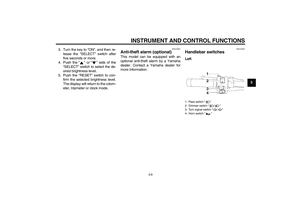
EAU12347
Handlebar switches Left1. Pass switch“”
2. Dimmer switch“/”
3. Turn signal switch“/”
4. Horn switch“”
U11CE1E0.book Page 9 Friday, August 31, 2007 1:25 PM
Page 24 of 88

INSTRUMENT AND CONTROL FUNCTIONS
3-10
3Right
EAU12350
Pass switch“”
Press this switch to flash the headlight.
EAU12400
Dimmer switch“/”
Set this switch to“” for the high
beam and to“” for the low beam.
EAU12460
Turn signal switch“/”
To signal a right-hand turn, push this
switch to“”. To signal a left-hand
turn, push this switch to“”. When re-
leased, the switch returns to the centerposition. To cancel the turn signal
lights, push the switch in after it has re-
turned to the center position.
EAU12500
Horn switch“”
Press this switch to sound the horn.
EAU12660
Engine stop switch“/”
Set this switch to“” before starting
the engine. Set this switch to“” to
stop the engine in case of an emergen-
cy, such as when the vehicle overturns
or when the throttle cable is stuck.
EAU12710
Start switch“”
Push this switch to crank the engine
with the starter.CAUTION:
ECA10050
See page 5-1 for starting instruc-tions prior to starting the engine.
EAU41700
The engine trouble warning light will
come on when the key is turned to “ON”
and the start switch is pushed, but this
does not indicate a malfunction.
EAU12733
Hazard switch“”
With the key in the “ON” or“” posi-
tion, use this switch to turn on the haz-
ard lights (simultaneous flashing of all
turn signal lights).
The hazard lights are used in case of
an emergency or to warn other drivers
when your vehicle is stopped where it
might be a traffic hazard.CAUTION:
ECA10061
Do not use the hazard lights for an
extended length of time with the en-
gine not running, otherwise the bat-tery may discharge.
EAU42522
“SELECT” switch“/”
This switch is used to perform selec-
tions in the odometer, tripmeter and
clock mode of the multi-function meter
unit.
See “Multi-function meter unit” on page
3-6 for detailed information.
1. Engine stop switch“/”
2. Hazard switch“”
3.“SELECT” switch“/”
4.“RESET” switch
5. Start switch“”U11CE1E0.book Page 10 Friday, August 31, 2007 1:25 PM