Page 32 of 78
PRE-OPERATION CHECKS
4-3
4
Wheels and tiresCheck for damage.
Check tire condition and tread depth.
Check air pressure.
Correct if necessary.6-13, 6-15
Brake leversMake sure that operation is smooth.
Lubricate lever pivoting points if necessary.6-18
Centerstand, sidestandMake sure that operation is smooth.
Lubricate pivots if necessary.6-19
Chassis fastenersMake sure that all nuts, bolts and screws are properly tightened.
Tighten if necessary.—
Instruments, lights, signals
and switchesCheck operation.
Correct if necessary.—
Sidestand switchCheck operation of ignition circuit cut-off system.
If system is defective, have Yamaha dealer check vehicle.3-13 ITEM CHECKS PAGE
Page 35 of 78

OPERATION AND IMPORTANT RIDING POINTS
5-3
5 down when approaching such
areas and cross them with cau-
tion.
�
Keep in mind that braking on a
wet road is much more difficult.
�
Ride slowly down a hill, as brak-
ing downhill can be very diffi-cult.
EAU16820
Tips for reducing fuel con-
sumption Fuel consumption depends largely on
your riding style. Consider the following
tips to reduce fuel consumption:�
Avoid high engine speeds during
acceleration.
�
Avoid high engine speeds with no
load on the engine.
�
Turn the engine off instead of let-
ting it idle for an extended length of
time (e.g., in traffic jams, at traffic
lights or at railroad crossings).
EAU16841
Engine break-in There is never a more important period
in the life of your engine than the period
between 0 and 1600 km (1000 mi). For
this reason, you should read the follow-
ing material carefully.
Since the engine is brand new, do not
put an excessive load on it for the first
1600 km (1000 mi). The various parts in
the engine wear and polish themselves
to the correct operating clearances.
During this period, prolonged full-throt-
tle operation or any condition that might
result in engine overheating must be
avoided.
EAUM2010
0–1000 km (0–600 mi)
Avoid prolonged operation above 1/3
throttle.
1000–1600 km (600–1000 mi)
Avoid prolonged operation above 1/2
throttle.
Page 39 of 78

PERIODIC MAINTENANCE AND MINOR REPAIR
6-3
6
10*TiresCheck tread depth and for damage.
Replace if necessary.
Check air pressure.
Correct if necessary.√√√√ √
11*Wheel bearingsCheck bearing for looseness or damage.√√√√
12*Steering bearingsCheck bearing play and steering for roughness.√√√√√
Lubricate with lithium-soap-based grease. Every 20000 km
13*Chassis fastenersMake sure that all nuts, bolts and screws are properly
tightened.√√√√ √
14 Sidestand, centerstandCheck operation.
Lubricate.√√√√ √
15*Sidestand switchCheck operation.√√√√√ √
16*Front forkCheck operation and for oil leakage.√√√√
17*Shock absorber assem-
bliesCheck operation and shock absorbers for oil leakage.√√√√
18*Fuel injectionCheck engine idle speed.√√√√√ √
19 Engine oilChange. (See page 3-2.)√When the oil change indicator light comes
on (every 3000 km)
Check oil level and vehicle for oil leakage. Every 3000 km√
20*Engine oil strainerClean.√
21*Cooling systemCheck coolant level and vehicle for coolant leakage.√√√√ √
Change. Every 3 years
22 Final transmission oilCheck vehicle for oil leakage.√√ √
Change.√√√
23*V- b e l tReplace. Every 20000 km NO. ITEM CHECK OR MAINTENANCE JOBODOMETER READING (× 1000 km)
ANNUAL
CHECK
1 10203040
Page 40 of 78
PERIODIC MAINTENANCE AND MINOR REPAIR
6-4
6
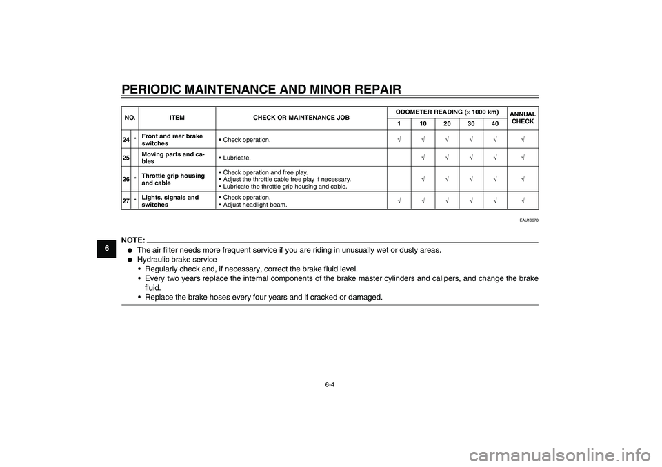
EAU18670
NOTE:�
The air filter needs more frequent service if you are riding in unusually wet or dusty areas.
�
Hydraulic brake service
Regularly check and, if necessary, correct the brake fluid level.
Every two years replace the internal components of the brake master cylinders and calipers, and change the brake
fluid.Replace the brake hoses every four years and if cracked or damaged.
24*Front and rear brake
switchesCheck operation.√√√√√ √
25Moving parts and ca-
blesLubricate.√√√√ √
26*Throttle grip housing
and cableCheck operation and free play.
Adjust the throttle cable free play if necessary.
Lubricate the throttle grip housing and cable.√√√√ √
27*Lights, signals and
switchesCheck operation.
Adjust headlight beam.√√√√√ √ NO. ITEM CHECK OR MAINTENANCE JOBODOMETER READING (× 1000 km)
ANNUAL
CHECK
1 10203040
Page 41 of 78
PERIODIC MAINTENANCE AND MINOR REPAIR
6-5
6
EAU18712
Removing and installing cowl-
ings and panels The cowlings and panels shown need
to be removed to perform some of the
maintenance jobs described in this
chapter. Refer to this section each time
a cowling or panel needs to be re-
moved and installed.
EAUM2221
Cowling A
To remove the cowling1. Remove the cowling screws.2. Disconnect the headlight coupler
and the turn signal couplers.
3. Pull the cowling off.
1. Cowling AZAUM0652
1
1. Panel A
1. Panel BZAUM0653
1
ZAUM0654
1
1. Cowling A
2. Screw
1. Turn signal light lead coupler
2. Headlight couplerZAUM0655
2
1
12
ZAUM0428
Page 42 of 78

PERIODIC MAINTENANCE AND MINOR REPAIR
6-6
6To install the cowling
1. Connect the headlight coupler and
the turn signal couplers.
2. Place the cowling in the original
position, and then install the
screws.
EAU19481
Panel A
To remove the panel1. Open the seat. (See page 3-10.)
2. Remove the screws, and then pull
the panel off as shown.
To install the panelPlace the panel in the original position,
and then install the screws.
EAU19210
Panel B
To remove the panelRemove the screws, and then take the
panel off.
To install the panelPlace the panel in the original position,
and then install the screws.
EAU19620
Checking the spark plug The spark plug is an important engine
component, which should be checked
periodically, preferably by a Yamaha
dealer. Since heat and deposits will
cause any spark plug to slowly erode, it
should be removed and checked in ac-
cordance with the periodic mainte-
nance and lubrication chart. In addition,
the condition of the spark plug can re-
veal the condition of the engine.
The porcelain insulator around the cen-
ter electrode of the spark plug should
be a medium-to-light tan (the ideal color
when the vehicle is ridden normally). If
the spark plug shows a distinctly differ-
ent color, the engine could be defec-
tive. Do not attempt to diagnose such
problems yourself. Instead, have a
Yamaha dealer check the vehicle.
If the spark plug shows signs of elec-
trode erosion and excessive carbon or
other deposits, it should be replaced.
1. Screw
2. Panel AZAUM0656
1
2
1. ScrewZAUM0657
1
Specified spark plug:
NGK/DPR8EA-9
Page 43 of 78

PERIODIC MAINTENANCE AND MINOR REPAIR
6-7
6 Before installing a spark plug, the spark
plug gap should be measured with a
wire thickness gauge and, if necessary,
adjusted to specification.
Clean the surface of the spark plug
gasket and its mating surface, and then
wipe off any grime from the spark plug
threads.
NOTE:If a torque wrench is not available when
installing a spark plug, a good estimate
of the correct torque is 1/4–1/2 turn
past finger tight. However, the spark
plug should be tightened to the speci-fied torque as soon as possible.
EAUM1550
Engine oil The engine oil level should be checked
before each ride. In addition, the oil
must be changed at the intervals spec-
ified in the periodic maintenance and
lubrication chart and when the service
indicator light comes on.
To check the engine oil level
1. Place the scooter on the center-
stand.NOTE:Make sure that the scooter is posi-
tioned straight up when checking the oil
level. A slight tilt to the side can result ina false reading.
2. Start the engine, warm it up for
several minutes, and then turn it
off.
3. Wait a few minutes until the oil set-
tles, remove the oil filler cap, wipe
the dipstick clean, insert it back
into the oil filler hole (without
screwing it in), and then remove it
again to check the oil level.
1. Spark plug gapSpark plug gap:
0.8–0.9 mm (0.031–0.035 in)
Tightening torque:
Spark plug:
17.5 Nm (1.75 m·kgf, 12.5 ft·lbf)
1
ZAUM0037
Page 46 of 78

PERIODIC MAINTENANCE AND MINOR REPAIR
6-10
66. Add the specified amount of the
recommended final transmission
oil, and then install and tighten the
oil filler cap.
WARNING
EWA11310
�
Make sure that no foreign mate-
rial enters the final transmission
case.
�
Make sure that no oil gets on thetire or wheel.
7. Check the final transmission case
for oil leakage. If oil is leaking,
check for the cause.
EAU20070
Coolant The coolant level should be checked
before each ride. In addition, the cool-
ant must be changed at the intervals
specified in the periodic maintenance
and lubrication chart.
EAUM2101
To check the coolant level
1. Place the vehicle on a level sur-
face and hold it in an upright posi-
tion.NOTE:�
The coolant level must be checked
on a cold engine since the level
varies with engine temperature.
�
Make sure that the vehicle is posi-
tioned straight up when checking
the coolant level. A slight tilt to theside can result in a false reading.
2. Check the coolant level through
the check window.
NOTE:The coolant should be between theminimum and maximum level marks.3. If the coolant is at or below the
minimum level mark, remove the
cowling A. (See page 6-5.)
4. Open the reservoir cap, and then
add coolant to the maximum level
mark.
Recommended final transmission
oil:
See page 8-1.
Oil quantity:
0.25 L (0.26 US qt) (0.22 Imp.qt)
1. Maximum level mark
2. Minimum level mark
1. Coolant reservoir cap
1
2
ZAUM0660
1
ZAUM0661