2008 YAMAHA WR 250F clutch
[x] Cancel search: clutchPage 60 of 224

3-5
PRE-OPERATION INSPECTION AND MAINTENANCE
PRE-OPERATION INSPECTION AND MAINTENANCE
Before riding for break-in operation or practice, make sure the machine is in good operating condition.
Before using this machine, check the following points.
GENERAL INSPECTION AND MAINTENANCEItem RoutinePage
Coolant Check that coolant is filled up to the radiator cap. Check the cool-
ing system for leakage. P.3-9 – 10
Fuel Check that a fresh gasoline is filled in the fuel tank. Check the fuel
line for leakage.
P.1-14
Engine oil Check that the oil level is correct. Check the crankcase and oil line
for leakage. P.3-12 – 14
Gear shifter and clutch Check that gears can be shifted correctly in order and that the
clutch operates smoothly. P.3-10
Throttle grip/Housing Check that the throttle grip operation and free play are correctly
adjusted. Lubricate the throttle grip and housing, if necessary.
P.3-10 – 11
Brakes Check the play of front brake and ef fect of front and rear brake. P.3-17 – 20
Drive chain Check drive chain slack and alignment. Check that the drive chain
is lubricated properly. P.3-20 – 21
Wheels Check for excessive wear and ti
re pressure. Check for loose
spokes and have no excessive play. P.3-24
Steering Check that the handlebar can be turned smoothly and have no ex-
cessive play.
P.3-24 – 25
Front forks and rear shock
absorber Check that they operate smoothly and there is no oil leakage.
P.3-21 – 24
Cables (wires) Check that the clutch and throttle cables move smoothly. Check
that they are not caught when the handlebars are turned or when
the front forks travel up and down. —
Exhaust pipe Check that the exhaust pipe is tightly mount ed and has no cracks. P.3-8 – 9
Rear wheel sprocket Check that the rear wheel sprocket tightening bolt is not loose. P.3-20
Lubrication Check for smooth operation. Lubricate if necessary. P.3-26
Bolts and nuts Check the chassis and engine for loose bolts and nuts. P.1-16
Lead connectors Check that the AC magneto, CDI unit, and ignition coil are con-
nected tightly. P.1-3
Settings Is the machine set suitably for the
condition of the racing course
and weather or by taking into account the results of test runs be-
fore racing? Are inspection and maintenance completely done? P.4-1 – 9
Page 65 of 224

3-10
ENGINE
Handling notes of coolant:
The coolant is harmful so it should be
handled with special care.
• When coolant splashes to your eye.
Thoroughly wash your eye with
water and see your doctor.
• When coolant splashes to your clothes.
Quickly wash it away with water
and then with soap.
• When coolant is swallowed. Quickly make him vomit and take
him to a doctor.
9. Install:• Radiator cap
Start the engine and warm it up
for a several minutes.
10. Check:
• Coolant levelCoolant level low →Add coolant.
CHECKING THE RADIATOR CAP
1. Inspect: • Seal (radiator cap) "1"
• Valve and valve seat "2"Crack/damage →Replace.
Exist fur deposits "3" →Clean or
replace.
CHECKING THE RADIATOR CAP
OPENING PRESSURE
1. Attach: • Radiator cap tester "1" and adapt-er "2"
Apply water on the radiator cap seal.
3. Radiator cap
2. Apply the specified pressure.
3. Inspect: •PressureImpossible to maintain the speci-
fied pressure for 10 seconds →
Replace.
CHECKING THE COOLING
SYSTEM
1. Inspect: • Coolant level
2. Attach: • Radiator cap tester "1" and adapt-
er "2"
3. Apply the specified pressure.
• Do not apply pressure more than specified pressure.
• Radiator should be filled fully.
4. Inspect: •PressureImpossible to maintain the speci-
fied pressure for 10 seconds →
Repair.
• Radiator "1"
• Radiator hose joint "2" Coolant leakage →Repair or re-
place.
• Radiator hose "3" Swelling →Replace. ADJUSTING THE CLUTCH CABLE
FREE PLAY
1. Check:
• Clutch lever free play "a"Out of specification →Adjust.
2. Adjust: • Clutch lever free play
Clutch lever free play adjustment
steps:
a. Loosen the locknuts "1".
b. Adjust the free play by changing their tightening position.
c. Tighten the locknuts.
• Make minute adjustment on the le- ver side using the adjuster "2".
• After adjustment, check proper op- eration of clutch lever.
ADJUSTING THE THROTTLE
CABLE FREE PLAY
1. Check:
• Throttle grip free play "a"Out of specification →Adjust.
Radiator cap tester:
YU-24460-01/90890-
01325
Radiator cap tester
adapter: YU-33984/90890-01352
Radiator cap opening
pressure:110 kPa (1.1 kg/cm
2,
15.6 psi)
Radiator cap tester: YU-24460-01/90890-
01325
Radiator cap tester
adapter:
YU-33984/90890-01352
Standard pressure: 180 kPa (1.8 kg/cm
2,
25.6 psi)
Clutch lever free play "a"
: 8–13 mm (0.31–0.51 in)
Locknut: 7 Nm (0.7 m•kg, 5.1
ft•lb)
Throttle grip free play
"a": 3–5 mm (0.12–0.20 in)
Page 67 of 224

3-12
ENGINE
5. Inspect:• Air filter elementDamage →Replace.
6. Apply:
• Foam-air-filter oil or equivalent oil to the element
• Squeeze out the excess oil. Ele-ment should be wet but not drip-
ping.
• Wipe off the oil left on the element surface using a clean dry cloth. (Ex-
cess oil in the element may ad-
versely affect engine starting.)
7. Install:• Air filter guide "1"
• Align the projection "a" on filter guide with the hole "b" in air filter el-
ement.
• Apply the lithium soap base grease on the matching surface "c" on air
filter element.
8. Install:
• Air filter element "1"
Align the projection "a" on filter guide
with the hole "b" in air filter case.
9. Hook:•Binder "1"
Hook the binder "1" so that it contacts
the filter guide projections "a".
CHECKING THE ENGINE OIL
LEVEL
1. Start the engine, warm it up for several minutes, and then turn off
the engine and wait for five min-
utes.
2. Place the machine on a level
place and hold it up on upright po-
sition by placing the suitable
stand under the engine.
3. Inspect: • Oil levelOil should be up to the full level in
the check window "1".
Level check window is not full. →
Add 0.2 L (0.18 Imp qt, 0.21 US
qt) of oil.
(For USA and CDN)
• Do not add any chemical addi- tives. Engine oil also lubricates
the clutch and additives could
cause clutch slippage.
• Do not allow foreign material to enter the crankcase.
(Except for USA and CDN)
• Do not add any chemical addi-tives or use oils with a grade of
CD "a" or higher.
• Do not use oils labeled "ENERGY CONSERVING II" "b" or higher.
Engine oil also lubricates the
clutch and additives could cause
clutch slippage.
• Do not allow foreign material to enter the crankcase.
4. Install:
• Oil tank cap
5. Start the engine and let it warm up for several minutes.
6. Turn off the engine and inspect the oil level once again.
Wait a few minutes until the oil settles
before inspecting the oil level.
CHANGING THE ENGINE OIL
1. Start the engine and warm it up for several minutes, and then turn
off the engine and wait for five
minute.
2. Place the machine on a level place and hold it on upright posi-
tion by placing the suitable stand
under the engine.
3. Place a suitable container under
the engine.
Recommended oil:Yamalube 4,
SAE10W30 or
SAE20W40
Yamalube 4-R,
SAE10W50
API service SG type or
higher, JASO standard
MA
Recommended oil: SAE10W30,
SAE10W40,
SAE15W40, SAE20W40
or SAE20W50
API service SG type or
higher, JASO standard
MA
Page 81 of 224
3-26
CHASSIS
LUBRICATION
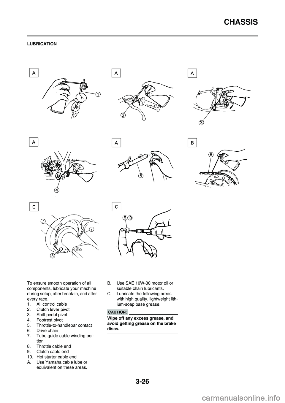
To ensure smooth operation of all
components, lubricate your machine
during setup, after break-in, and after
every race.
1. All control cable
2. Clutch lever pivot
3. Shift pedal pivot
4. Footrest pivot
5. Throttle-to-handlebar contact
6. Drive chain
7. Tube guide cable winding por-tion
8. Throttle cable end
9. Clutch cable end
10. Hot starter cable end
A. Use Yamaha cable lube or equivalent on these areas. B. Use SAE 10W-30 motor oil or
suitable chain lubricants.
C. Lubricate the following areas
with high quality, lightweight lith-
ium-soap base grease.
Wipe off any excess grease, and
avoid getting grease on the brake
discs.
Page 125 of 224

5-29
CLUTCH
CLUTCH
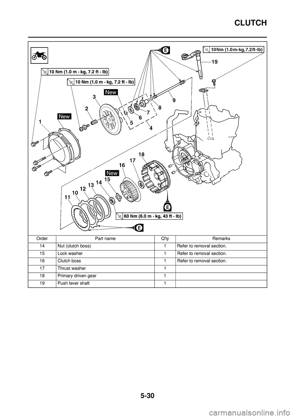
REMOVING THE CLUTCHOrder Part name Q'ty Remarks Drain the engine oil. Refer to "CHANGING THE ENGINE OIL"
section in the CHAPTER 3.
Brake pedal Refer to "ENGINE REMOVAL" section.
Clutch cable Disconnect at engine side.
1 Clutch cover 1
2 Clutch spring 5
3 Pressure plate 1
4 Push rod 1 1
5 Circlip 1
6 Washer 1
7 Bearing 1
8Ball 1
9 Push rod 2 1
10 Friction plate 9
11 Clutch plate 8
12 Cushion spring 1
13 Seat plate 1
Page 126 of 224
5-30
CLUTCH
14 Nut (clutch boss)1 Refer to removal section.
15 Lock washer 1 Refer to removal section.
16 Clutch boss 1 Refer to removal section.
17 Thrust washer 1
18 Primary driven gear 1
19 Push lever shaft 1
Order
Part name Q'tyRemarks
Page 127 of 224

5-31
CLUTCH
REMOVING THE CLUTCH BOSS
1. Remove:•Nut "1"
• Lock washer "2"
• Clutch boss "3"
Straighten the lock washer tab and
use the clutch holding tool "4" to hold
the clutch boss.
A. For USA and CDN
B. Except for USA and CDN
CHECKING THE CLUTCH
HOUSING AND BOSS
1. Inspect: • Clutch housing "1"
Cracks/wear/damage →Replace.
• Clutch boss "2" Scoring/wear/damage →Replace.
CHECKING THE PRIMARY DRIVEN
GEAR
1. Check: • Circumferential play
Free play exists →Replace.
• Gear teeth "a" Wear/damage →Replace. CHECKING THE CLUTCH
SPRINGS
1. Measure:
• Clutch spring free length "a"
Out of specification →Replace
springs as a set.
CHECKING THE FRICTION
PLATES
1. Measure: • Friction plate thickness
Out of specification →Replace
friction plate as a set.
Measure at all four points.
CHECKING THE CLUTCH PLATES
1. Measure: • Clutch plate warpageOut of specification →Replace
clutch plate as a set.
Use a surface plate "1" and thick-
ness gauge "2". CHECKING THE PUSH LEVER
SHAFT
1. Inspect:
• Push lever shaft "1"
Wear/damage →Replace.
CHECKING THE PUSH ROD
1. Inspect: • Push rod 1 "1"
• Bearing "2"
• Washer "3"
• Push rod 2 "4"
•Ball "5"Wear/damage/bend →Replace.
INSTALLING THE PUSH LEVER
SHAFT
1. Install: • Push lever shaft "1"
• Bolt (push lever shaft) "2"
• Apply the lithium soap base grease
on the oil seal lip.
• Apply the engine oil on the push le- ver shaft.
• Fit the seat plate "3" in the groove "a" of the push lever shaft and tight-
en the bolt (seat plate).
INSTALLING THE CLUTCH
1. Install:• Primary driven gear "1"
• Thrust washer "2"
• Clutch boss "3"
Clutch holding tool:
YM-91042/90890-04086
Clutch spring free
length:
37.0 mm (1.46 in)
in)
Friction plate thickness: 2.9–3.1 mm (0.114–
0.122 in)
in)
Warp limit: 0.1 mm (0.004 in)
Bolt (push lever shaft): 10 Nm (1.0 m•kg, 7.2
ft•lb)
Page 128 of 224

5-32
CLUTCH
Apply the engine oil on the primary
driven gear inner circumference.
2. Install:• Lock washer "1"
• Nut (clutch boss) "2"
Use the clutch holding tool "3" to hold
the clutch boss.
A. For USA and CDN
B. Except for USA and CDN
3. Bend the lock washer "1" tab.
4. Install: • Seat plate "1"
• Cushion spring "2"
• Install the seat plate with its cham-fered portion "a" facing the clutch
boss "3".
• Install the seat plate so that it is not caught on the step "b".
• Install the cushion spring with the paint "c" facing out.
5. Install:
• Friction plate 1 "1"
• Clutch plate 1 "2"
• Friction plate 2 "3"
• Clutch plate 2 "4"
• Install the clutch plates and friction plates alternately on the clutch
boss, starting with a friction plate
and ending with a friction plate.
• Use the friction plates 1 for the first and final while paying attention to
the difference in surface pattern.
• Apply the engine oil on the friction plates and clutch plates.
• Unlike the clutch pl ate 2, the clutch
plate 1 has no surface gloss. Use
the clutch plate 1 for the first while
paying attention to the difference in
surface gloss.
6. Install:
•Bearing "1"
• Washer "2"
• Circlip "3" To push rod 1 "4".
Apply the engine oil on the bearing
and washer.
7. Install:• Push rod 2 "1"
•Ball "2"
• Push rod 1 "3"
Apply the engine oil on the push rod
1, 2 and ball.
8. Install:• Pressure plate "1"
9. Install: • Clutch spring "1"
• Bolt (clutch spring) "2"
Tighten the bolts in stage, using a
crisscross pattern.
Nut (clutch boss): 60 Nm (6.0 m•kg, 43
ft•lb)
Clutch holding tool: YM-91042/90890-04086
Bolt (clutch spring):10 Nm (1.0 m•kg, 7.2
ft•lb)