2008 YAMAHA WR 250F oil filter
[x] Cancel search: oil filterPage 67 of 224

3-12
ENGINE
5. Inspect:• Air filter elementDamage →Replace.
6. Apply:
• Foam-air-filter oil or equivalent oil to the element
• Squeeze out the excess oil. Ele-ment should be wet but not drip-
ping.
• Wipe off the oil left on the element surface using a clean dry cloth. (Ex-
cess oil in the element may ad-
versely affect engine starting.)
7. Install:• Air filter guide "1"
• Align the projection "a" on filter guide with the hole "b" in air filter el-
ement.
• Apply the lithium soap base grease on the matching surface "c" on air
filter element.
8. Install:
• Air filter element "1"
Align the projection "a" on filter guide
with the hole "b" in air filter case.
9. Hook:•Binder "1"
Hook the binder "1" so that it contacts
the filter guide projections "a".
CHECKING THE ENGINE OIL
LEVEL
1. Start the engine, warm it up for several minutes, and then turn off
the engine and wait for five min-
utes.
2. Place the machine on a level
place and hold it up on upright po-
sition by placing the suitable
stand under the engine.
3. Inspect: • Oil levelOil should be up to the full level in
the check window "1".
Level check window is not full. →
Add 0.2 L (0.18 Imp qt, 0.21 US
qt) of oil.
(For USA and CDN)
• Do not add any chemical addi- tives. Engine oil also lubricates
the clutch and additives could
cause clutch slippage.
• Do not allow foreign material to enter the crankcase.
(Except for USA and CDN)
• Do not add any chemical addi-tives or use oils with a grade of
CD "a" or higher.
• Do not use oils labeled "ENERGY CONSERVING II" "b" or higher.
Engine oil also lubricates the
clutch and additives could cause
clutch slippage.
• Do not allow foreign material to enter the crankcase.
4. Install:
• Oil tank cap
5. Start the engine and let it warm up for several minutes.
6. Turn off the engine and inspect the oil level once again.
Wait a few minutes until the oil settles
before inspecting the oil level.
CHANGING THE ENGINE OIL
1. Start the engine and warm it up for several minutes, and then turn
off the engine and wait for five
minute.
2. Place the machine on a level place and hold it on upright posi-
tion by placing the suitable stand
under the engine.
3. Place a suitable container under
the engine.
Recommended oil:Yamalube 4,
SAE10W30 or
SAE20W40
Yamalube 4-R,
SAE10W50
API service SG type or
higher, JASO standard
MA
Recommended oil: SAE10W30,
SAE10W40,
SAE15W40, SAE20W40
or SAE20W50
API service SG type or
higher, JASO standard
MA
Page 68 of 224

3-13
ENGINE
4. Remove:• Engine guard "1"
• Bolt (oil tank) "2"
• Washer "3"
• Oil filler cap "4"
• Oil tank drain bolt "5"
• Crankcase oil drain bolt "6"
• Oil filter element drain bolt "7"Drain the crankcase and oil tank
of its oil.
5. Remove: • Oil hose clamp "1"
• Bolt (oil hose)
• Oil hose "2"
• Oil strainer "3"
6. Inspect: • Oil strainerClogged →Blow.
7. If the oil filter is to be replaced dur-
ing this oil change, remove the fol-
lowing parts and reinstall them.
Replacement steps:
a. Remove the oil filter element cov-er "1" and oil filter element "2".
b. Check the O-rings "3", if cracked or damaged, replace them with a
new one.
c. Install the oil filter element and oil filter element cover.
8. Install:• O-ring "1"
• Oil strainer "2"
• Oil hose
• Bolt (oil hose)
• Oil hose clamp
9. Install: • Copper washer
• Oil filter element drain bolt
• Crankcase oil drain bolt
• Oil tank drain bolt
• Engine guard 10. Fill:
• Engine oil
11. Check: • Oil leakage
12. Install: • Oil filler cap
• Washer (oil tank)
• Bolt (oil tank)
13. Check: • Engine oil level
CHECKING THE OIL PRESSURE
1. Check: • Oil pressure
Checking steps:
a. Slightly loosen the oil pressure check bolt "1".
b. Start the engine and keep it idling
until oil starts to seep from the oil
pressure check bolt. If no oil
comes out after one minute, turn
the engine off so it will not seize.
c. Check oil passages and oil pump for damage or leakage.
d. Start the engine after solving the problem(s) and recheck the oil
pressure.
e. Tighten the oil pressure check bolt.
Oil filter element cover:10 Nm (1.0 m•kg, 7.2
ft•lb)
Oil strainer: 9 Nm (0.9 m•kg, 6.5
ft•lb)
Bolt (oil hose): 8 Nm (0.8 m•kg, 5.8
ft•lb)
Oil hose clamp: 2 Nm (0.2 m•kg, 1.4
ft•lb)
Oil filter element drain
bolt: 10 Nm (1.0 m•kg, 7.2
ft•lb)
Crankcase oil drain bolt: 20 Nm (2.0 m•kg, 14
ft•lb)
Oil tank drain bolt: 18 Nm (1.8 m•kg, 13
ft•lb)
Engine guard: 7 Nm (0.7 m•kg, 5.1
ft•lb)
Oil quantity: Periodic oil change:1.1 L (0.97 Imp qt, 1.16
US qt)
With oil filter replace-
ment:
1.2 L (1.06 Imp qt, 1.27
US qt)
Total amount:
1.4 L (1.23 Imp qt, 1.48
US qt)
Bolt (oil tank): 7 Nm (0.7 m•kg, 5.1
ft•lb)
Oil pressure check bolt: 10 Nm (1.0 m•kg, 7.2
ft•lb)
Page 130 of 224

5-34
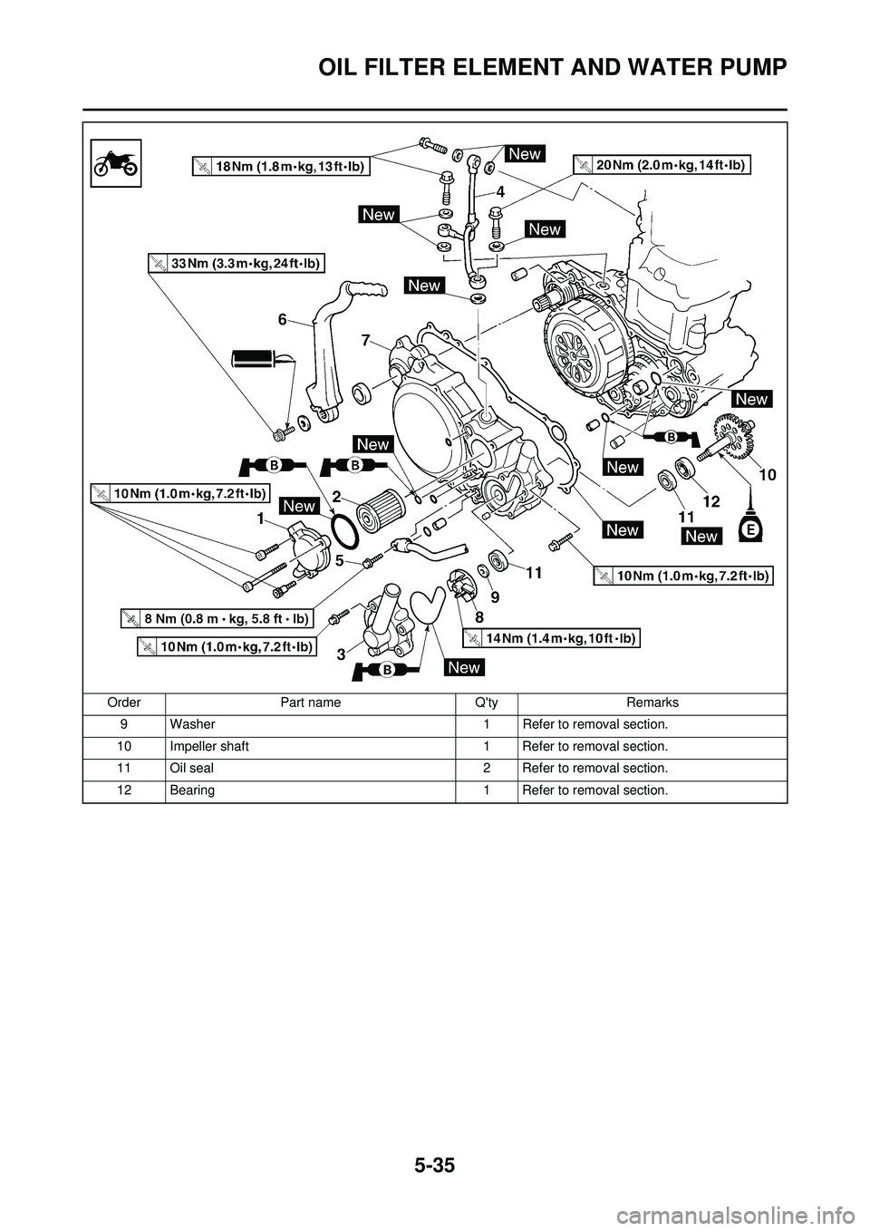
OIL FILTER ELEMENT AND WATER PUMP
OIL FILTER ELEMENT AND WATER PUMP
REMOVING THE OIL FILTER ELEMENT AND WATER PUMPOrder Part name Q'ty Remarks Drain the engine oil. Refer to "CHANGING THE ENGINE OIL"
section in the CHAPTER 3.
Drain the coolant. Refer to "CHANGING
THE COOLANT" sec-
tion in the CHAPTER 3.
Radiator hose 3 Disconnect at water pump side.
Exhaust pipe Refer to "REMOVING THE EXHAUST PIPE
AND SILENCER" section in the CHAPTER 3.
Brake pedal Refer to "ENGINE REMOVAL" section.
Engine guard
1 Oil filter element cover 1
2 Oil filter element 1
3 Water pump housing 1
4 Oil delivery pipe 1
5 Bolt (oil hose) 1
6 Kickstarter crank 1
7 Right crankcase cover 1
8 Impeller 1 Refer to removal section.
Page 131 of 224
5-35
OIL FILTER ELEMENT AND WATER PUMP
9 Washer1 Refer to removal section.
10 Impeller shaft 1 Refer to removal section.
11 Oil seal 2 Refer to removal section.
12 Bearing 1 Refer to removal section.
Order
Part name Q'tyRemarks
Page 132 of 224

5-36
OIL FILTER ELEMENT AND WATER PUMP
REMOVING THE IMPELLER
SHAFT
1. Remove:• Impeller "1"
• Washer "2"
• Impeller shaft "3"
Hold the impeller shaft on its width
across the flats "a" with spanners,
etc. and remove the impeller.
REMOVING THE OIL SEAL
It is not necessary to disassemble the
water pump, unless there is an abnor-
mality such as excessive change in
coolant level, discoloration of coolant,
or milky transmission oil.
1. Remove:• Bearing "1"
2. Remove: • Oil seal "1"
CHECKING THE OIL DELIVERY
PIPE
1. Inspect: • Oil delivery pipe "1"Bend/damage →Replace.
Clogged →Blow. CHECKING THE IMPELLER SHAFT
1. Inspect:
• Impeller shaft "1"Bend/wear/damage →Replace.
Fur deposits →Clean.
CHECKING THE IMPELLER SHAFT
GEAR
1. Inspect: • Gear teeth "a"Wear/damage →Replace.
CHECKING THE BEARING
1. Inspect: •BearingRotate inner race with a finger.
Rough spot/seizure →Replace.
CHECKING THE OIL SEAL
1. Inspect: • Oil seal "1"Wear/damage →Replace. INSTALLING THE OIL SEAL
1. Install:
• Oil seal "1"
• Apply the lithium soap base grease on the oil seal lip.
• Install the oil seal with its manufac- ture's marks or numbers facing the
right crankcase cover "2".
2. Install:• Bearing "1"
Install the bearing by pressing its out-
er race parallel.
INSTALLING THE IMPELLER
SHAFT
1. Install:• Impeller shaft "1"
• Washer "2"
• Impeller "3"
• Take care so that the oil seal lip is
not damaged or the spring does not
slip off its position.
• When installing the impeller shaft,
apply the lithium soap base grease
on the oil seal lip and impeller shaft.
And install the shaft while turning it.
• Hold the impeller shaft on its width across the flats "a" with spanners,
etc. and install the impeller.
Impeller: 14 Nm (1.4 m•kg, 10
ft•lb)
Page 133 of 224

5-37
OIL FILTER ELEMENT AND WATER PUMP
INSTALLING THE RIGHT
CRANKCASE COVER
1. Install:• Dowel pin "1"
• O-ring "2"
•Collar "3"
• Gasket "4"
Apply the lithium soap base grease
on the O-ring.
2. Install:• Right crankcase cover "1"
• Bolt (right crankcase cover) "2"
• Apply the engine oil on the impeller shaft end.
• Mesh the impeller shaft gear "3"
with primary drive gear "4".
• Tighten the bolts in stage, using a crisscross pattern.
INSTALLING THE KICKSTARTER
CRANK
1. Install:• Kickstarter crank "1"
• Washer "2"
• Bolt (kickstarter crank) "3"
Install so that there is a clearance "a"
of 13 mm (0.51 in) or more between
the kickstarter and frame and that the
kickstarter does not contact the
crankcase cover when it is pulled.
2. Install:
• Oil hose "1"
• Bolt (oil hose) "2"
3. Install: • Copper washer "1"
• Oil delivery pipe "2"
• Union bolt (M8) "3"
• Union bolt (M10) "4" INSTALLING THE WATER PUMP
HOUSING
1. Install:
• Dowel pin "1"
• O-ring "2"
Apply the lithium soap base grease
on the O-ring.
2. Install:
• Water pump housing "1"
• Bolt (water pump housing) "2"
INSTALLING THE OIL FILTER
ELEMENT
1. Install: • Oil filter element "1"
• O-ring "2"
• Oil filter element cover "3"
• Bolt (oil filter element cover)
Apply the lithium soap base grease
on the O-ring.
Bolt (right crankcase
cover): 10 Nm (1.0 m•kg, 7.2
ft•lb)
Bolt (kickstarter crank):33 Nm (3.3 m•kg, 24
ft•lb)
Bolt (oil hose): 8 Nm (0.8 m•kg, 5.8
ft•lb)
Union bolt (M8): 18 Nm (1.8 m•kg, 13
ft•lb)
Union bolt (M10): 20 Nm (2.0 m•kg, 14
ft•lb)
Bolt (water pump hous-
ing):
10 Nm (1.0 m•kg, 7.2
ft•lb)
Bolt (oil filter element
cover): 10 Nm (1.0 m•kg, 7.2
ft•lb)
Page 134 of 224
5-38
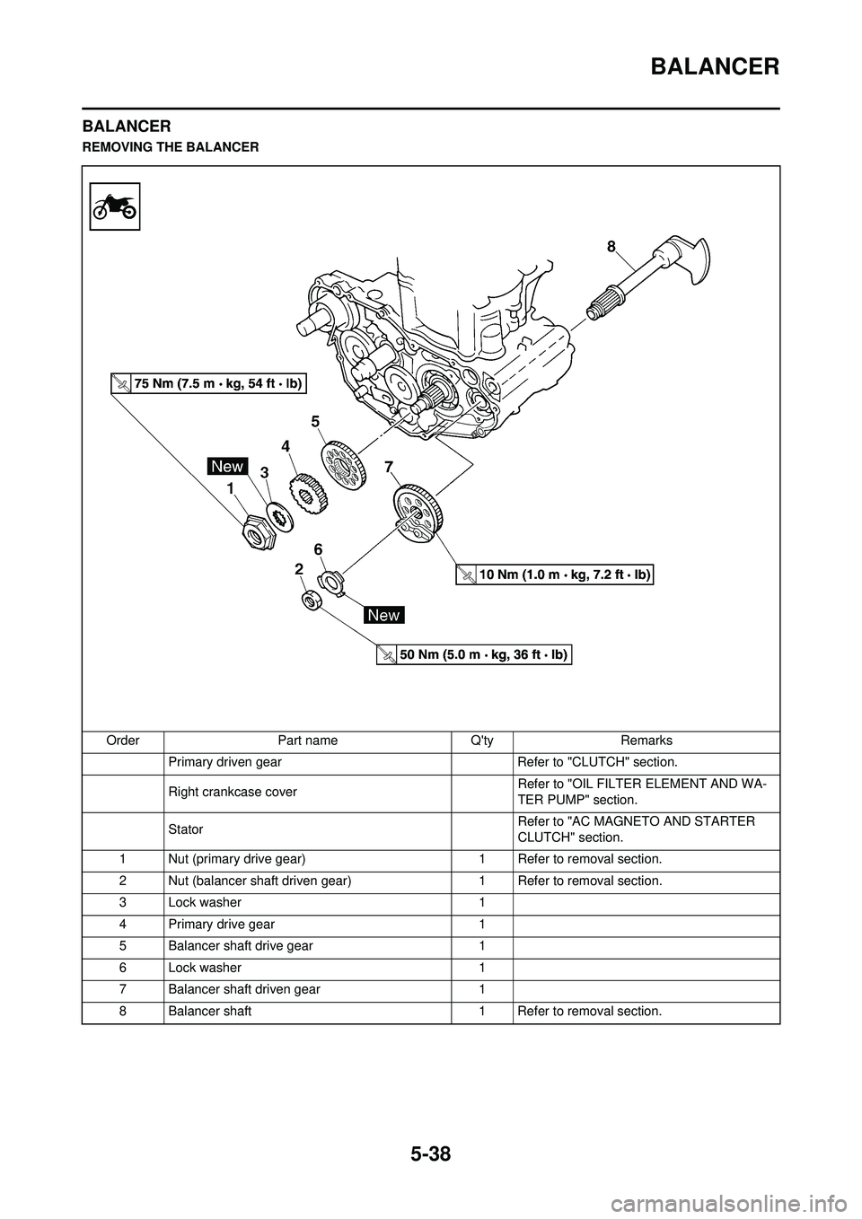
BALANCER
BALANCER
REMOVING THE BALANCEROrder Part name Q'ty Remarks Primary driven gear Refer to "CLUTCH" section.
Right crankcase cover Refer to "OIL FILTER ELEMENT AND WA-
TER PUMP" section.
Stator Refer to "AC MAGNETO AND STARTER
CLUTCH" section.
1 Nut (primary drive gear) 1 R efer to removal section.
2 Nut (balancer shaft driven gear) 1 Refer to removal section.
3 Lock washer 1
4 Primary drive gear 1
5 Balancer shaft drive gear 1
6 Lock washer 1
7 Balancer shaft driven gear 1
8 Balancer shaft 1 Refer to removal section.
Page 136 of 224
5-40
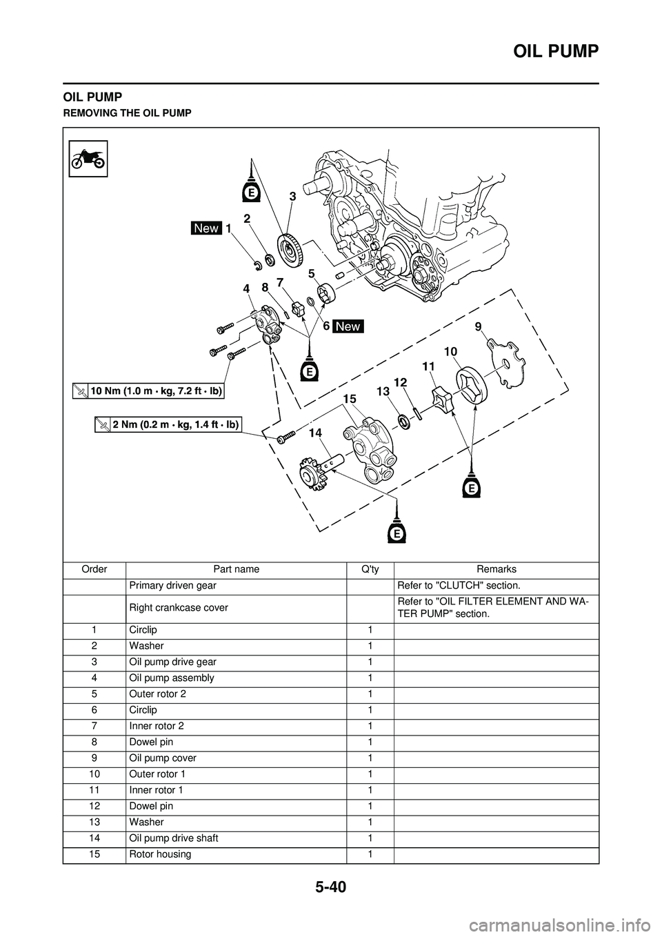
OIL PUMP
OIL PUMP
REMOVING THE OIL PUMPOrder Part name Q'ty Remarks Primary driven gear Refer to "CLUTCH" section.
Right crankcase cover Refer to "OIL FILTER ELEMENT AND WA-
TER PUMP" section.
1 Circlip 1
2 Washer 1
3 Oil pump drive gear 1
4 Oil pump assembly 1
5 Outer rotor 2 1
6 Circlip 1
7 Inner rotor 2 1
8 Dowel pin 1
9 Oil pump cover 1
10 Outer rotor 1 1
11 Inner rotor 1 1
12 Dowel pin 1
13 Washer 1
14 Oil pump drive shaft 1
15 Rotor housing 1