Page 202 of 275

The appearance of the engine compartment may vary depending on engine model.
Coolant expansion tank
Power steering fluid reservoir
Engine oil dipstick
Radiator
Filler cap for engine oil
Cover over brake fluid reservoir
Battery
Relay and fuse box
Washer fluid reservoir
Air cleaner
WARNING
The cooling fan may start or continue to operate (for up to 6 minutes) after the engine has been switched off.
WARNING
The ignition should always be completely switched off before performing any operations in the engine compartment.
The distributor ignition system operates at very high voltages. Special safety precautions must be followed to prevent
injury. Always turn the ignition off when:
Replacing distributor ignition components e.g. plugs, coil, etc.
Do not touch any part of the distributor ignition system while the engine is running. This may result in unintended
movements and body injury.
212 06 Maintenance and specifications
Engine oil
Checking the engine oil
The oil level should be checked every time the vehicle is refueled. This is especially important during the period up to
the first scheduled maintenance service.
See page 272 for oil specifications.
Refer to the Warranty and Service Records Information booklet for information on the oil change intervals.
Volvo recommends Castrol.
CAUTION
Not checking the oil level regularly can result in serious engine damage if the oil level becomes too low.
Oil that is lower than the specified quality can damage the engine.
Page 218 of 275
The windshield and headlight washers share a common reservoir.
The washer fluid reservoir is located on the driver's side of the engine compartment. During cold weather, the reservoir
should be filled with windshield washer solvent containing antifreeze. For capacities, see page 275
.
226 06 Maintenance and specifications
Battery
Warning symbols on the battery
NOTE
A used battery should be disposed of in an environmentally responsible manner. Consult your Volvo retailer or take
the battery to a recycling station.
Handling
Check that the battery cables are correctly connected and tightened.
Never disconnect the battery when the engine is running (for example, when replacing the battery).
Page 219 of 275
The service life and function of the battery is influenced by factors such as the number of starts, discharging, driving
style, driving conditions, climatic conditions etc.
Never use a quick charger to charge the battery.
WARNING
Never expose the battery to open flame or electric spark.
Do not smoke near the battery.
Battery fluid contains sulfuric acid. Do not allow battery fluid to contact eyes, skin, fabrics or painted surfaces. If
contact occurs, flush the affected area immediately with water. Obtain medical help immediately if eyes are affected.
NOTE
The life of the battery is shortened if it becomes discharged repeatedly.
227 06 Maintenance and specifications
Battery
Maintenance
Regularly check that the electrolyte level is correct and never fill above the level mark.
Check all cells. Use a large screwdriver or a coin to remove the cell caps. Each cell has its own maximum and
minimum level mark.
If necessary, top up with distilled water to the battery's maximum mark.
Tighten the cell caps thoroughly.
CAUTION
Always use distilled or deionized water (battery water).
Never fill above the level mark in the cell.
228 06 Maintenance and specifications
Battery
Changing
Page 220 of 275
WARNING
Connect and disconnect the positive and negative cables in the correct sequence.
Removal
Switch off the ignition and wait at least 5 minutes before disconnecting the battery so that all information in the
vehicle's electrical system can be stored in the control modules.
Open the clips on the front cover and remove the cover.
Release the rubber moulding so that the rear cover is free.
Remove the rear cover by pulling it away.
Page 221 of 275
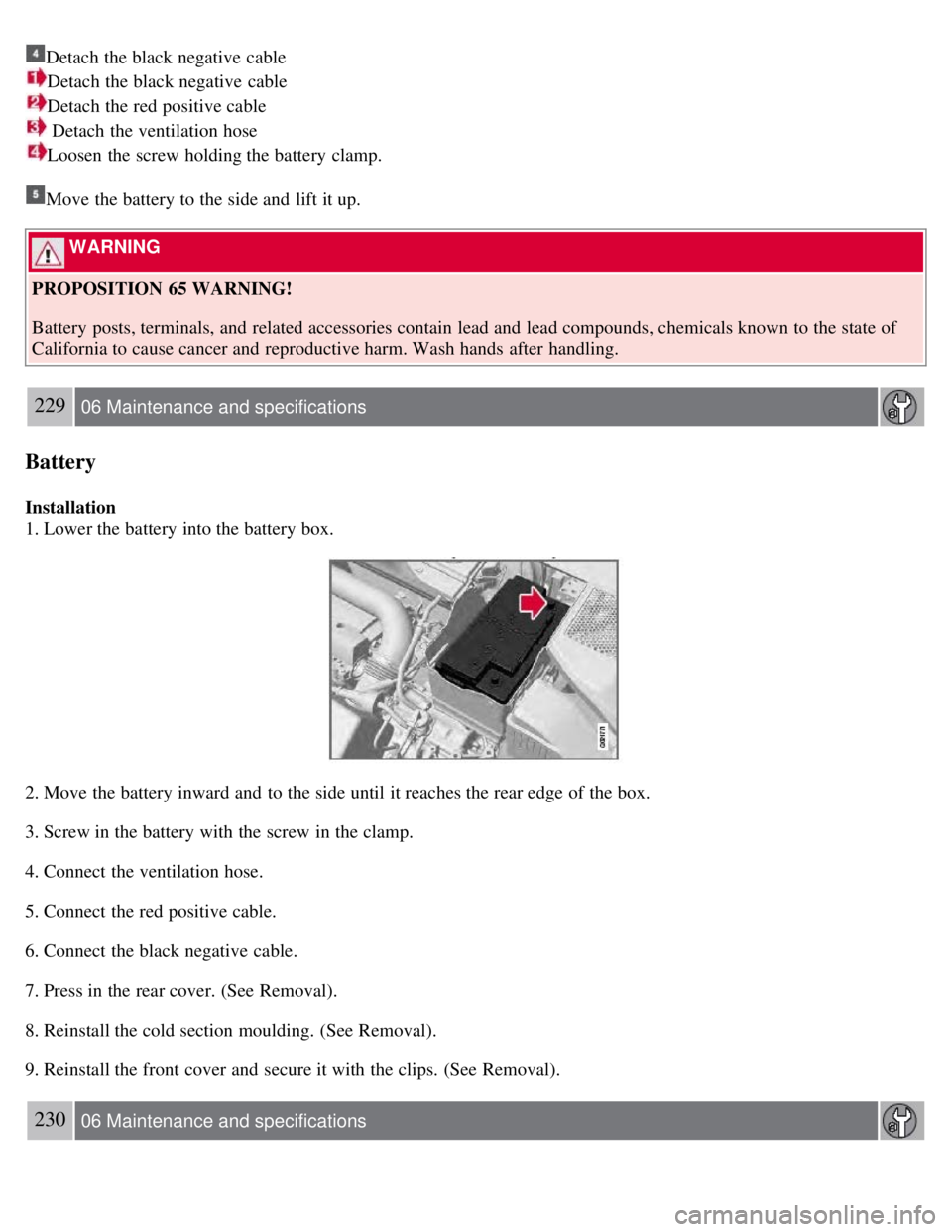
Detach the black negative cable
Detach the black negative cable
Detach the red positive cable
Detach the ventilation hose
Loosen the screw holding the battery clamp.
Move the battery to the side and lift it up.
WARNING
PROPOSITION 65 WARNING!
Battery posts, terminals, and related accessories contain lead and lead compounds, chemicals known to the state of
California to cause cancer and reproductive harm. Wash hands after handling.
229 06 Maintenance and specifications
Battery
Installation
1. Lower the battery into the battery box.
2. Move the battery inward and to the side until it reaches the rear edge of the box.
3. Screw in the battery with the screw in the clamp.
4. Connect the ventilation hose.
5. Connect the red positive cable.
6. Connect the black negative cable.
7. Press in the rear cover. (See Removal).
8. Reinstall the cold section moulding. (See Removal).
9. Reinstall the front cover and secure it with the clips. (See Removal).
230 06 Maintenance and specifications
Page 248 of 275
Skin: Wash affected areas of skin with soap and water. Get medical attention if symptoms occur.
Eyes: Flush with plenty of water for least 15 minutes, occasionally lifting the upper and lower eyelids. Get
medical attention if symptoms occur.
Inhalation: Move the person to fresh air. If irritation persists, get medical attention
1Certain markets only.
258 06 Maintenance and specifications
Wheels and tires
Inflating tires
The tire sealing system can be used to inflate the tires. To do so:
1. Park the car in a safe place.
2. The compressor should be switched off. Ensure that the on/off switch is in position 0 (the 0 side of the switch should
be pressed down).
3. Take out the electrical wire and hose.
4. Remove the valve cap from the tire's inflation valve and screw the hose connector onto the valve as tightly as
possible by hand.
5. Connect the electrical wire to the nearest 12-volt socket in the vehicle.
6. Start the vehicle's engine.
WARNING
The vehicle's engine should be running when the tire sealing system is used to avoid battery drain. Therefore, be
sure the vehicle is parked in a well ventilated place, or outdoors, before using the system.
Children should never be left unattended in the vehicle when the engine is running.
7. Check the tire's inflation pressure on the gauge. Switch off the compressor briefly to get a clear reading from the
pressure gauge.
8. Refer to the tables on pages 240 and 241
for the correct tire inflation pressure. If the tire needs to be inflated, start
the tire sealing system's compressor (press the on/off switch to position I ). If necessary, release air from the tire by
turning the air release knob counterclockwise.
CAUTION
The compressor should not be used for more than 10 minutes at a time to avoid overheating.
9. Turn off the compressor (press the on/off switch to position 0) when the correct inflation pressure has been reached.
10. Unscrew the hose from the tire's inflation valve and reinstall the valve cap.
11. Disconnect the electrical wire from the 12-volt socket.
Page 250 of 275
Contact with the sealing compound may cause skin irritation. If contact occurs, wash the affected area immediately
with soap and water.
5. Unscrew the orange cover over the bottle holder and unscrew the cap on the bottle of sealing compound.
NOTE
Do not break the seal on the bottle. This occurs automatically when the bottle is screwed into the holder.
6. Screw the bottle into the bottle holder.
WARNING
The bottle is equipped with a catch to keep it securely in place and help prevent sealing compound leakage. Once in
place, the bottle cannot be unscrewed. This must be done by a trained and qualified Volvo service technician.
7. Remove the valve cap from the tire's inflation valve and screw the tire sealing system's hose connector onto the
valve as tightly as possible by hand.
260 06 Maintenance and specifications
Wheels and tires
8. Connect the electrical wire to the nearest 12-volt socket in the vehicle.
9. Start the vehicle's engine.
WARNING
The vehicle's engine should be running when the tire sealing system is used to avoid battery drain. Therefore, be sure
the vehicle is parked in a well ventilated place, or outdoors, before using the system.
10. Start the tire sealing system's compressor by pressing the on/off switch to position I .
WARNING
Never stand next to the tire being inflated when the compressor is in operation.
If cracks, bubbles, etc. form on the tire, switch off the compressor immediately.
If there is visible damage to the sidewall or the rim, the tire cannot be repaired. The vehicle should not be driven if
this occurs. Contact a towing service or Volvo On Call Roadside Assistance if applicable.
NOTE
The air pressure gauge will temporarily show an increase in pressure to approximately 88 psi (6 bar) while the
sealing compound is being pumped into the tire. The pressure should return to a normal level after approximately 30
seconds.
11. Within seven minutes, inflate the tire to between 22-44 psi (1.8-3.0 bar). Switch off the compressor briefly to get a
clear reading from the pressure gauge.
Page 262 of 275
driving conditions.
2Models without headlight washers
276 06 Maintenance and specifications
Specifications
Electrical system
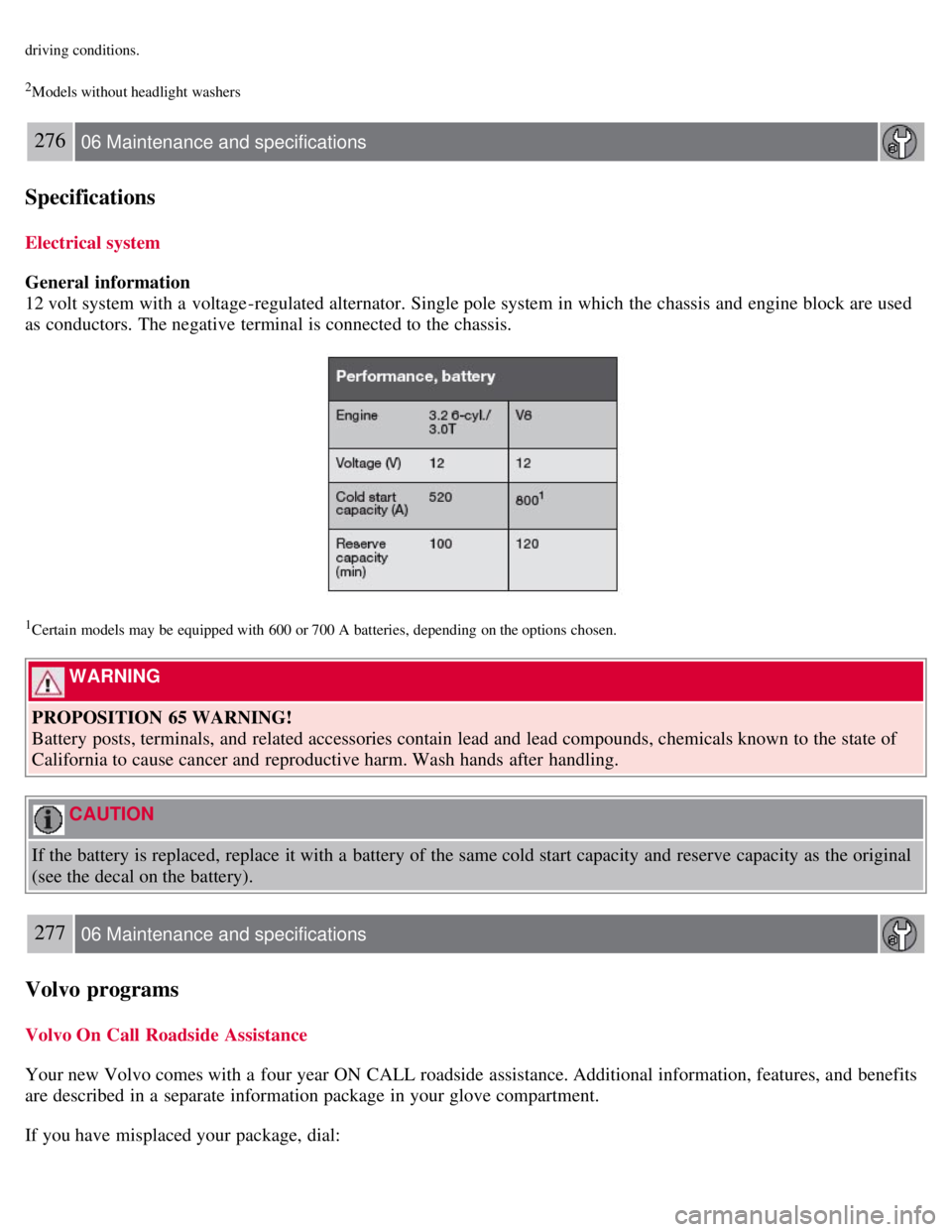
General information
12 volt system with a voltage -regulated alternator. Single pole system in which the chassis and engine block are used
as conductors. The negative terminal is connected to the chassis.
1Certain models may be equipped with 600 or 700 A batteries, depending on the options chosen.
WARNING
PROPOSITION 65 WARNING!
Battery posts, terminals, and related accessories contain lead and lead compounds, chemicals known to the state of
California to cause cancer and reproductive harm. Wash hands after handling.
CAUTION
If the battery is replaced, replace it with a battery of the same cold start capacity and reserve capacity as the original
(see the decal on the battery).
277 06 Maintenance and specifications
Volvo programs
Volvo On Call Roadside Assistance
Your new Volvo comes with a four year ON CALL roadside assistance. Additional information, features, and benefits
are described in a separate information package in your glove compartment.
If you have misplaced your package, dial: