2008 VOLVO S80 inflation pressure
[x] Cancel search: inflation pressurePage 235 of 275

NOTE
TPMS indicates low tire pressure but does not replace normal tire maintenance. For information on correct tire
pressure, please refer to the tables beginning on page 240
, or consult your Volvo retailer.
The tire pressure warning light will not identify which tire is under-inflated. Be sure to check all four tires.
A certain amount of air seepage from the tires occurs naturally and tire pressure fluctuates with seasonal changes
in temperature. Always check tire pressure regularly.
Erasing warning messages
When a low tire pressure warning message has been displayed, and the tire pressure warning light has come on:
1. Use a tire pressure gauge to check the inflation pressure of all four tires.
2. Re-inflate the tire(s) to the correct pressure (consult the tire pressure placard or the tables beginning on page 240
).
3. In certain cases, it may be necessary to drive the vehicle for several minutes at a speed of 20 mph (30 km/h) or
faster. This will erase the warning text and the warning light will go out.
WARNING
Incorrect inflation pressure could lead to tire failure, resulting in a loss of control of the vehicle.
Changing wheels with TPMS
Please note the following when changing or replacing the factory installed TPMS wheels/tires on the vehicle:
Only the factory-mounted wheels are equipped with TPMS sensors in the valves.
If the vehicle is equipped with a temporary spare tire, this tire does not have a TPMS sensor.
If wheels without TPMS sensors are mounted on the vehicle, TIRE PRESS SYST SERVICE REQUIRED will be
displayed each time the vehicle is driven above 25 mph (40 km/h) for 10 minutes or more.
Once TPMS sensors are properly installed, the warning message should not reappear. If the message is still
displayed, drive the vehicle for several minutes at a speed of 20 mph (30 km/h) or faster to erase the message.
Volvo recommends that TPMS sensors be fitted on all wheels used on the vehicle. Volvo does not recommend
moving sensors back and forth between sets of wheels.
NOTE
If you change to tires with a different recommended inflation pressure, the TPMS system must be recalibrated to
these tires. This must be done by a trained and qualified Volvo service technician.
If a tire is changed, or if the TPMS sensor is moved to another wheel, the sensor's seal, nut, and valve core should
be replaced.
When installing TPMS sensors, the vehicle must be parked for at least 15 minutes with the ignition off. if the
vehicle is driven within 15 minutes, a TPMS error message will be displayed.
CAUTION
When inflating tires with TPMS valves, press the pump's mouthpiece straight onto the valve to help avoid bending or
otherwise damaging the valve.
244 06 Maintenance and specifications
Wheels and tires
Page 236 of 275
Self supporting run flat tires
Certain models equipped with the Tire Pressure Monitoring System (TPMS) can also be equipped with self supporting
run flat tires.
Tires of this type have specially reinforced sidewalls that make it possible to continue driving in the event of a drop in
inflation pressure. Tires of this type are mounted on special rims.
NOTE
Self supporting run flat tires are only available in conjunction with TPMS.
If a self supporting run flat tire should lose inflation pressure, the yellow TPMS warning symbol (
) in the
instrument panel lights up to alert the driver, and a message will be shown in the text window in the instrument panel.
If this occurs, reduce vehicle speed to a maximum of 50 mph (80 km/h). The vehicle can be driven approximately 50
miles (80 km), or somewhat farther if the vehicle is not heavily loaded. The tire should be replaced as soon as
possible.
Hard braking and sudden steering maneuvers should be avoided.
In certain cases, it may be difficult to see which self supporting run flat tire is defective. To determine which tire is
damaged, check the inflation pressure of all four tires.
WARNING
Only specially trained persons should mount self supporting run flat tires.
If self supporting run flat tires are mounted, the vehicle must be equipped with a Tire Pressure Monitoring
System.
After a low pressure warning has been displayed, do not exceed 50 mph (80 km/h).
Avoid severe cornering and hard braking, and minimize the distance traveled before replacing the self supporting
run flat tire.
Self supporting run flat tires cannot be repaired. They must be replaced if damaged or punctured.
245 06 Maintenance and specifications
Wheels and tires
Tire designations
Federal law mandates that tire manufacturers place standardized information on the sidewall of all tires (see the
Page 237 of 275
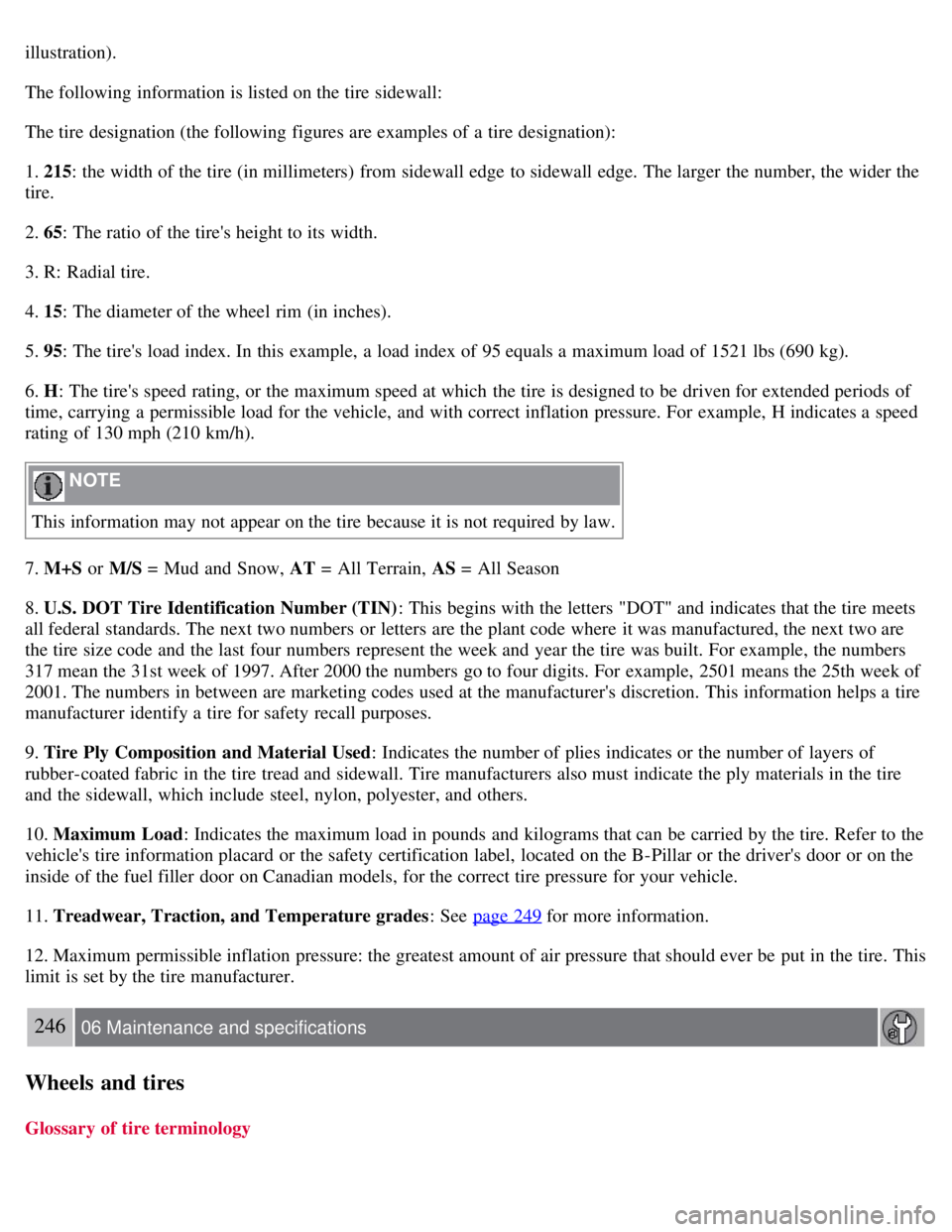
illustration).
The following information is listed on the tire sidewall:
The tire designation (the following figures are examples of a tire designation):
1. 215: the width of the tire (in millimeters) from sidewall edge to sidewall edge. The larger the number, the wider the
tire.
2. 65: The ratio of the tire's height to its width.
3. R: Radial tire.
4. 15: The diameter of the wheel rim (in inches).
5. 95: The tire's load index. In this example, a load index of 95 equals a maximum load of 1521 lbs (690 kg).
6. H: The tire's speed rating, or the maximum speed at which the tire is designed to be driven for extended periods of
time, carrying a permissible load for the vehicle, and with correct inflation pressure. For example, H indicates a speed
rating of 130 mph (210 km/h).
NOTE
This information may not appear on the tire because it is not required by law.
7. M+S or M/S = Mud and Snow, AT = All Terrain, AS = All Season
8. U.S. DOT Tire Identification Number (TIN) : This begins with the letters "DOT" and indicates that the tire meets
all federal standards. The next two numbers or letters are the plant code where it was manufactured, the next two are
the tire size code and the last four numbers represent the week and year the tire was built. For example, the numbers
317 mean the 31st week of 1997. After 2000 the numbers go to four digits. For example, 2501 means the 25th week of
2001. The numbers in between are marketing codes used at the manufacturer's discretion. This information helps a tire
manufacturer identify a tire for safety recall purposes.
9. Tire Ply Composition and Material Used : Indicates the number of plies indicates or the number of layers of
rubber-coated fabric in the tire tread and sidewall. Tire manufacturers also must indicate the ply materials in the tire
and the sidewall, which include steel, nylon, polyester, and others.
10. Maximum Load : Indicates the maximum load in pounds and kilograms that can be carried by the tire. Refer to the
vehicle's tire information placard or the safety certification label, located on the B-Pillar or the driver's door or on the
inside of the fuel filler door on Canadian models, for the correct tire pressure for your vehicle.
11. Treadwear, Traction, and Temperature grades : See page 249
for more information.
12. Maximum permissible inflation pressure: the greatest amount of air pressure that should ever be put in the tire. This
limit is set by the tire manufacturer.
246 06 Maintenance and specifications
Wheels and tires
Glossary of tire terminology
Page 238 of 275
The tire suppliers may have additional markings, notes or warnings such as standard load, radial tubeless, etc.
Tire information placard: A placard showing the OE (Original Equipment) tire sizes, recommended inflation
pressure, and the maximum weight the vehicle can carry.
Tire Identification Number (TIN) : A number on the sidewall of each tire providing information about the tire
brand and manufacturing plant, tire size and date of manufacturer.
Inflation pressure : A measure of the amount of air in a tire.
Standard load: A class of P-metric or Metric tires designed to carry a maximum load at 35 psi [37 psi (2.5 bar) for
Metric tires]. Increasing the inflation pressure beyond this pressure will not increase the tires load carrying capability.
Extra load : A class of P-metric or Metric tires designed to carry a heavier maximum load at 41 psi [43 psi (2.9 bar)
for Metric tires]. Increasing the inflation pressure beyond this pressure will not increase the tire's load carrying
capability.
kPa : Kilopascal, a metric unit of air pressure.
PSI: Pounds per square inch, a standard unit of air pressure.
B-pillar: The structural member at the side of the vehicle behind the front door.
Bead area of the tire : Area of the tire next to the rim.
Sidewall of the tire: Area between the bead area and the tread.
Tread area of the tire : Area of the perimeter of the tire that contacts the road when mounted on the vehicle.
Rim: The metal support (wheel) for a tire or a tire and tube assembly upon which the tire beads are seated.
Maximum load rating : a figure indicating the maximum load in pounds and kilograms that can be carried by the
tire. This rating is established by the tire manufacturer.
Maximum permissible inflation pressure : the greatest amount of air pressure that should ever be put in the tire.
This limit is set by the tire manufacturer.
Recommended tire inflation pressure : inflation pressure, established by Volvo, which is based on the type of tires
that are mounted on a vehicle at the factory. This inflation pressure is affected by the number of occupants in the
vehicle, the amount of cargo, and the speed at which the vehicle will be driven for a prolonged period. This
information can be found on the tire inflation placard(s) located on the driver's side B-pillar or on the inside of the fuel
filler door on Canadian models, and in the tire inflation table in this chapter.
Cold tires : The tires are considered to be cold when they have the same temperature as the surrounding (ambient)
air. This temperature is normally reached after the vehicle has been parked for at least 3 hours.
247 06 Maintenance and specifications
Wheels and tires
Vehicle loading
Properly loading your vehicle will provide maximum return of vehicle design performance.
Before loading your vehicle, familiarize yourself with the following terms for determining your vehicle's weight
ratings, with or without a trailer, from the vehicle's Federal/Canadian Motor Vehicle Safety Standards
(FMVSS/CMVSS) label, and the vehicle's tire information placard:
Curb weight
The weight of the vehicle including a full tank of fuel and all standard equipment. It does not include passengers,
cargo, or optional equipment.
Capacity weight
All weight added to the curb weight, including cargo and optional equipment. When towing, trailer hitch tongue load
is also part of cargo weight.
NOTE
Page 246 of 275
Tire sealing system
Certain models are equipped with a tire sealing system that enables you to temporarily seal a hole in the tread surface
and reinflate a flat tire, or to adjust a tire's inflation pressure.
The system consists of an air compressor, a container for the sealing compound, wiring to connect the system to the
vehicle's electrical system via one of the 12-volt sockets, and a hose used to connect the system to the tire's inflation
valve.
The 12-volt sockets are located in the front tunnel console, on the rear side of the center console in the rear seat. See
page 185
.
Accessing the tire sealing system
The tire sealing system is stowed under the floor of the trunk. To access it:
1. Fold up the floor carpeting, starting at the rear and working forward.
2. Remove the retaining screws
3. Lift out the foam plastic block holding the jack and lug wrench.
4. Lift out the tire sealing system.
NOTE
The tire sealing system is only intended to seal holes on the tire's tread area, not the sidewall.
Tires with large holes or tears cannot be repaired with the tire sealing system.
WARNING
After using the tire sealing system, the vehicle should not be driven farther than approximately 120 miles (200
km).
Have the tire inspected by a qualified service technician as soon as possible to determine if it can be permanently
repaired or must be replaced.
The vehicle should not be driven faster than 50 mph (80 km/h) while using a tire that has been temporarily
repaired with the tire sealing system.
After using the tire sealing system, drive carefully and avoid abrupt steering maneuvers and sudden stops.
257 06 Maintenance and specifications
Wheels and tires
Tire sealing system -overview
Page 248 of 275
Skin: Wash affected areas of skin with soap and water. Get medical attention if symptoms occur.
Eyes: Flush with plenty of water for least 15 minutes, occasionally lifting the upper and lower eyelids. Get
medical attention if symptoms occur.
Inhalation: Move the person to fresh air. If irritation persists, get medical attention
1Certain markets only.
258 06 Maintenance and specifications
Wheels and tires
Inflating tires
The tire sealing system can be used to inflate the tires. To do so:
1. Park the car in a safe place.
2. The compressor should be switched off. Ensure that the on/off switch is in position 0 (the 0 side of the switch should
be pressed down).
3. Take out the electrical wire and hose.
4. Remove the valve cap from the tire's inflation valve and screw the hose connector onto the valve as tightly as
possible by hand.
5. Connect the electrical wire to the nearest 12-volt socket in the vehicle.
6. Start the vehicle's engine.
WARNING
The vehicle's engine should be running when the tire sealing system is used to avoid battery drain. Therefore, be
sure the vehicle is parked in a well ventilated place, or outdoors, before using the system.
Children should never be left unattended in the vehicle when the engine is running.
7. Check the tire's inflation pressure on the gauge. Switch off the compressor briefly to get a clear reading from the
pressure gauge.
8. Refer to the tables on pages 240 and 241
for the correct tire inflation pressure. If the tire needs to be inflated, start
the tire sealing system's compressor (press the on/off switch to position I ). If necessary, release air from the tire by
turning the air release knob counterclockwise.
CAUTION
The compressor should not be used for more than 10 minutes at a time to avoid overheating.
9. Turn off the compressor (press the on/off switch to position 0) when the correct inflation pressure has been reached.
10. Unscrew the hose from the tire's inflation valve and reinstall the valve cap.
11. Disconnect the electrical wire from the 12-volt socket.
Page 249 of 275
259 06 Maintenance and specifications
Wheels and tires
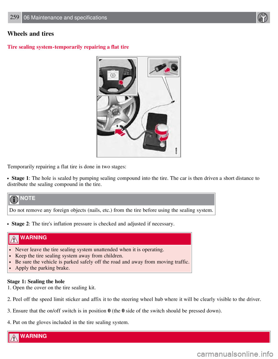
Tire sealing system-temporarily repairing a flat tire
Temporarily repairing a flat tire is done in two stages:
Stage 1: The hole is sealed by pumping sealing compound into the tire. The car is then driven a short distance to
distribute the sealing compound in the tire.
NOTE
Do not remove any foreign objects (nails, etc.) from the tire before using the sealing system.
Stage 2: The tire's inflation pressure is checked and adjusted if necessary.
WARNING
Never leave the tire sealing system unattended when it is operating.
Keep the tire sealing system away from children.
Be sure the vehicle is parked safely off the road and away from moving traffic.
Apply the parking brake.
Stage 1: Sealing the hole
1. Open the cover on the tire sealing kit.
2. Peel off the speed limit sticker and affix it to the steering wheel hub where it will be clearly visible to the driver.
3. Ensure that the on/off switch is in position 0 (the 0 side of the switch should be pressed down).
4. Put on the gloves included in the tire sealing system.
WARNING
Page 250 of 275
Contact with the sealing compound may cause skin irritation. If contact occurs, wash the affected area immediately
with soap and water.
5. Unscrew the orange cover over the bottle holder and unscrew the cap on the bottle of sealing compound.
NOTE
Do not break the seal on the bottle. This occurs automatically when the bottle is screwed into the holder.
6. Screw the bottle into the bottle holder.
WARNING
The bottle is equipped with a catch to keep it securely in place and help prevent sealing compound leakage. Once in
place, the bottle cannot be unscrewed. This must be done by a trained and qualified Volvo service technician.
7. Remove the valve cap from the tire's inflation valve and screw the tire sealing system's hose connector onto the
valve as tightly as possible by hand.
260 06 Maintenance and specifications
Wheels and tires
8. Connect the electrical wire to the nearest 12-volt socket in the vehicle.
9. Start the vehicle's engine.
WARNING
The vehicle's engine should be running when the tire sealing system is used to avoid battery drain. Therefore, be sure
the vehicle is parked in a well ventilated place, or outdoors, before using the system.
10. Start the tire sealing system's compressor by pressing the on/off switch to position I .
WARNING
Never stand next to the tire being inflated when the compressor is in operation.
If cracks, bubbles, etc. form on the tire, switch off the compressor immediately.
If there is visible damage to the sidewall or the rim, the tire cannot be repaired. The vehicle should not be driven if
this occurs. Contact a towing service or Volvo On Call Roadside Assistance if applicable.
NOTE
The air pressure gauge will temporarily show an increase in pressure to approximately 88 psi (6 bar) while the
sealing compound is being pumped into the tire. The pressure should return to a normal level after approximately 30
seconds.
11. Within seven minutes, inflate the tire to between 22-44 psi (1.8-3.0 bar). Switch off the compressor briefly to get a
clear reading from the pressure gauge.