Page 210 of 278

9-21INSPECTION AND MAINTENANCE
80J21-03E
BrakesBrake Fluid
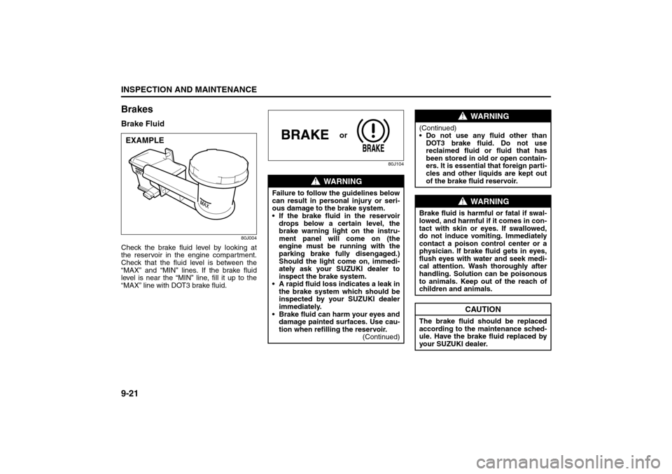
80J004
Check the brake fluid level by looking at
the reservoir in the engine compartment.
Check that the fluid level is between the
“MAX” and “MIN” lines. If the brake fluid
level is near the “MIN” line, fill it up to the
“MAX” line with DOT3 brake fluid.
80J104
EXAMPLE
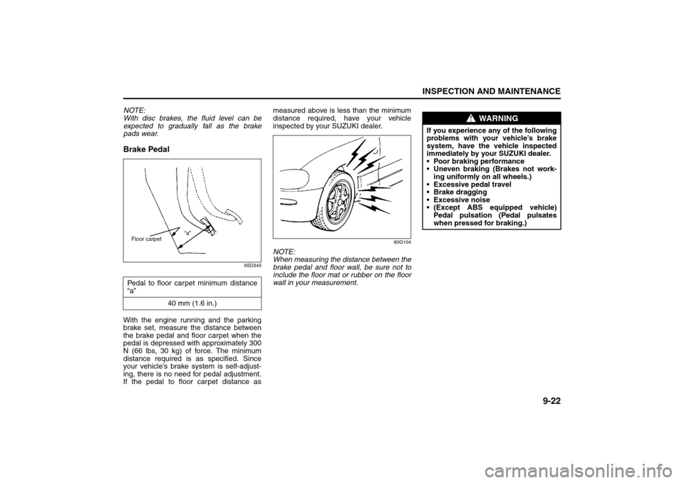
WARNING
Failure to follow the guidelines below
can result in personal injury or seri-
ous damage to the brake system.
If the brake fluid in the reservoir
drops below a certain level, the
brake warning light on the instru-
ment panel will come on (the
engine must be running with the
parking brake fully disengaged.)
Should the light come on, immedi-
ately ask your SUZUKI dealer to
inspect the brake system.
A rapid fluid loss indicates a leak in
the brake system which should be
inspected by your SUZUKI dealer
immediately.
Brake fluid can harm your eyes and
damage painted surfaces. Use cau-
tion when refilling the reservoir.
(Continued)
or
WARNING
(Continued)
Do not use any fluid other than
DOT3 brake fluid. Do not use
reclaimed fluid or fluid that has
been stored in old or open contain-
ers. It is essential that foreign parti-
cles and other liquids are kept out
of the brake fluid reservoir.
WARNING
Brake fluid is harmful or fatal if swal-
lowed, and harmful if it comes in con-
tact with skin or eyes. If swallowed,
do not induce vomiting. Immediately
contact a poison control center or a
physician. If brake fluid gets in eyes,
flush eyes with water and seek medi-
cal attention. Wash thoroughly after
handling. Solution can be poisonous
to animals. Keep out of the reach of
children and animals.
CAUTION
The brake fluid should be replaced
according to the maintenance sched-
ule. Have the brake fluid replaced by
your SUZUKI dealer.
Clutch Pedal: 6
Tires: 6
Page 211 of 278

9-22
INSPECTION AND MAINTENANCE
80J21-03E
NOTE:
With disc brakes, the fluid level can be
expected to gradually fall as the brake
pads wear.Brake Pedal
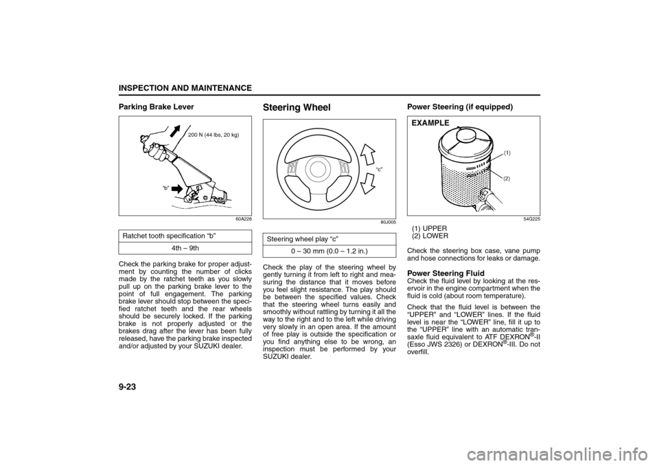
65D345
With the engine running and the parking
brake set, measure the distance between
the brake pedal and floor carpet when the
pedal is depressed with approximately 300
N (66 lbs, 30 kg) of force. The minimum
distance required is as specified. Since
your vehicle’s brake system is self-adjust-
ing, there is no need for pedal adjustment.
If the pedal to floor carpet distance asmeasured above is less than the minimum
distance required, have your vehicle
inspected by your SUZUKI dealer.
60G104
NOTE:
When measuring the distance between the
brake pedal and floor wall, be sure not to
include the floor mat or rubber on the floor
wall in your measurement.
Pedal to floor carpet minimum distance
“a”
40 mm (1.6 in.)
“a”
Floor carpet
WARNING
If you experience any of the following
problems with your vehicle’s brake
system, have the vehicle inspected
immediately by your SUZUKI dealer.
Poor braking performance
Uneven braking (Brakes not work-
ing uniformly on all wheels.)
Excessive pedal travel
Brake dragging
Excessive noise
(Except ABS equipped vehicle)
Pedal pulsation (Pedal pulsates
when pressed for braking.)
Tires: 6
Page 212 of 278

9-23INSPECTION AND MAINTENANCE
80J21-03E
Parking Brake Lever
60A226
Check the parking brake for proper adjust-
ment by counting the number of clicks
made by the ratchet teeth as you slowly
pull up on the parking brake lever to the
point of full engagement. The parking
brake lever should stop between the speci-
fied ratchet teeth and the rear wheels
should be securely locked. If the parking
brake is not properly adjusted or the
brakes drag after the lever has been fully
released, have the parking brake inspected
and/or adjusted by your SUZUKI dealer.
Steering Wheel
80J005
Check the play of the steering wheel by
gently turning it from left to right and mea-
suring the distance that it moves before
you feel slight resistance. The play should
be between the specified values. Check
that the steering wheel turns easily and
smoothly without rattling by turning it all the
way to the right and to the left while driving
very slowly in an open area. If the amount
of free play is outside the specification or
you find anything else to be wrong, an
inspection must be performed by your
SUZUKI dealer.
Power Steering (if equipped)
54G225
(1) UPPER
(2) LOWER
Check the steering box case, vane pump
and hose connections for leaks or damage.Power Steering FluidCheck the fluid level by looking at the res-
ervoir in the engine compartment when the
fluid is cold (about room temperature).
Check that the fluid level is between the
“UPPER” and “LOWER” lines. If the fluid
level is near the “LOWER” line, fill it up to
the “UPPER” line with an automatic tran-
saxle fluid equivalent to ATF DEXRON
®-II
(Esso JWS 2326) or DEXRON
®-III. Do not
overfill. Ratchet tooth specification “b”
4th – 9th
200 N (44 lbs, 20 kg)
“b”
Steering wheel play “c”
0 – 30 mm (0.0 – 1.2 in.)
“c”
EXAMPLE
Tires: 6
Page 221 of 278

9-32
INSPECTION AND MAINTENANCE
80J21-03E
GLOSSARY OF TIRE TERMINOL-
OGYAccessory Weight – the combined weight
(in excess of those standard items which
may be replaced) of automatic transaxle,
power steering, power brakes, power win-
dows, power seats, radio, and heater, to
the extent that these items are available as
factory-installed equipment (whether
installed or not).
Cold Tire Inflation Pressure – the pressure
in a tire that has been driven less than 1
mile or has been standing for three hours
or more.
Curb Weight – the weight of a motor vehi-
cle with standard equipment including the
maximum capacity of fuel, oil, and coolant,
and, if so equipped, air conditioning and
additional weight optional engine.
Intended Outboard Sidewall – (1) the side-
wall that contains a whitewall, bears white
lettering or bears manufacturer, brand,
and/or model name molding that is higher
or deeper than the same molding on the
other sidewall of the tire, or (2) the outward
facing sidewall of an asymmetrical tire that
has a particular side that must always face
outward when mounted on a vehicle.
Maximum Inflation Pressure – the maxi-
mum cold inflation pressure a tire is
designed to support in normal service.Maximum Loaded Vehicle Weight – the
sum of curb weight, accessory weight,
vehicle capacity weight (total load capac-
ity), and production options weight.
Normal Occupant Weight – 68 kilograms
times the number of occupants specified in
the second column of Table 1 (shown
below).
Occupant distribution – distribution of
occupants in a vehicle as specified in the
third column of Table 1 (shown below).
Production Options Weight – the combined
weight of those installed regular production
options weighing over 2.3 kilograms in
excess of those standard items which they
replace, not previously considered in curb
weight or accessory weight, including
heavy duty brakes, ride levelers, roof rack,
heavy duty battery, and special trim.
Recommended Inflation Pressure – the
cold tire inflation pressure recommended
by a manufacturer.
Rim – metal support for a tire or tire and
tube assembly upon which the tire beads
are seated.
Vehicle Capacity Weight – the rated cargo
and luggage load plus 68 kilograms (150
lbs) times the vehicle’s designated seating
capacity.Vehicle Maximum Load on the Tire – the
load on an individual tire that is determined
by distributing to each axle its share of the
maximum loaded vehicle weight and divid-
ing by two.
Vehicle Normal Load on the Tire – the load
on an individual tire that is determined by
distributing to each axle its share of the
curb weight, accessory weight, and normal
occupant weight (distributed in accordance
with Table 1 shown below) and dividing by
2.
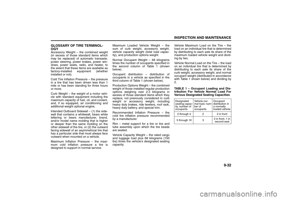
TABLE 1 – Occupant Loading and Dis-
tribution For Vehicle Normal Load For
Various Designated Seating Capacities
Designated
seating capac-
ity, number of
occupantsVehicle nor-
mal load, num-
ber of
occupantsOccupant
distribution in
a normally
loaded vehicle
2 through 4 2 2 in front
5 through 10 32 in front, 1 in
second seat
Fuses: 7
Page 225 of 278

9-36
INSPECTION AND MAINTENANCE
80J21-03E
Fuses in the Engine Compartment
80J051
80J052
(1)
(2) (3)
(28) (27) (26) (25) (6) (7) (9) (11)
(15) (16) (17) (18) (19)
(24)
(8) (4) (5) (10)
(22) (21)
(23)(20)(12) (13) (14)
(30)
(29)
MAIN FUSE / PRIMARY FUSE
(1) 80A All electric load
(2) 50APower window, Ignition,
Wiper, Starter
(3) 50ATail light, Rear defogger,
Door lock, Hazard/Horn,
Dome
(4) – Blank
(5) – Blank
(6) 15A Head light (Right) fuse
(7) 15A Head light (Left) fuse
(8) 20A Front fog light fuse
(9) – Blank
(10) 40A ABS control module fuse
(11) 30A Radiator fan fuse
(12) 30A ABS control module fuse
(13) 30A Starting motor fuse
(14) 50A Ignition switch fuse
(15) 30A Blower fan fuse
(16) 20A Air compressor fuse
(17) 15A Throttle motor fuse
(18) 15A Automatic transaxle fuse
(19) 15A Fuel injection fuse
(20) – Automatic transaxle relay
(21) – Air compressor relay
(22) – Fuel pump relay
(23) – Condenser fan relay
(24) – Front fog light relay
(25) – Throttle motor relay
(26) – FI MAIN
(27) – Starting motor relay
(28) – Radiator fan relay
(29) – Radiator fan relay 2
(30) – Radiator fan relay 3
Bulb Replacement: 7
Page 229 of 278
9-40
INSPECTION AND MAINTENANCE
80J21-03E
Center Interior Light (if equipped)
60G115
Pull down the lens by using a plain screw
driver covered with a soft cloth as shown.
To install it, simply push it back in.
The bulb can be removed by simply pulling
it out. When replacing the bulb, make sure
that the contact springs are holding the
bulb securely.
Headlights
65D149
54G121
Open the engine hood. Remove the cou-
pler and the rubber cover. Then unhook
the bulb holding spring and replace the
bulb.
Other General LightsBulb holder
54G123
(1) Removal
(2) Installation
To remove a bulb holder from a light hous-
ing, turn the holder counterclockwise and
pull it out. To install the holder, push the
holder in and turn it clockwise.
(1)
(1) (2)(2)
EXAMPLE
Wiper Blades: 3
Page 237 of 278
9-48
INSPECTION AND MAINTENANCE
80J21-03E
Air Conditioning SystemIf you do not use the air conditioner for a
long period, such as during winter, it may
not give the best performance when you
start using it again. To help maintain opti-
mum performance and durability of your air
conditioner, it needs to be run periodically.
Operate the air conditioner at least once a
month for one minute with the engine
idling. This circulates the refrigerant and oil
and helps protect the internal components.
Page 239 of 278
EMERGENCY SERVICE
10
80J21-03E
60G411
EMERGENCY SERVICEJacking Instructions ........................................................... 10-1
Jump Starting Instructions ................................................ 10-3
Towing a Disabled Vehicle ................................................. 10-4
If the Starter Does Not Operate .......................................... 10-4
If the Engine is Flooded ...................................................... 10-5
If the Engine Overheats ...................................................... 10-5
If You Can Not Shift Automatic Transaxle Gearshift
Lever Out of “P” (PARK) .................................................... 10-6