2008 SUZUKI SX4 door lock
[x] Cancel search: door lockPage 147 of 278
5-10
OTHER CONTROLS AND EQUIPMENT
80J21-03E
Eyeglasses Holder
(if equipped)
86G067
To use the eyeglasses holder, open the
cover. Do not put heavy or sharp items in
the box.
Engine Hood
79J077
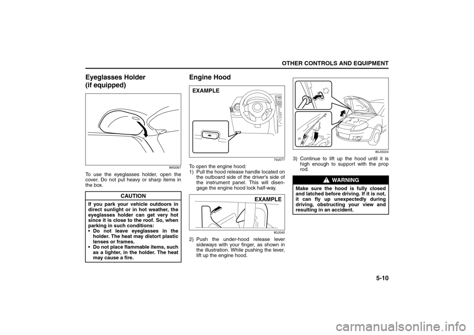
To open the engine hood:
1) Pull the hood release handle located on
the outboard side of the driver’s side of
the instrument panel. This will disen-
gage the engine hood lock half-way.
80J045
2) Push the under-hood release lever
sideways with your finger, as shown in
the illustration. While pushing the lever,
lift up the engine hood.
80JS024
3) Continue to lift up the hood until it is
high enough to support with the prop
rod.
CAUTION
If you park your vehicle outdoors in
direct sunlight or in hot weather, the
eyeglasses holder can get very hot
since it is close to the roof. So, when
parking in such conditions:
Do not leave eyeglasses in the
holder. The heat may distort plastic
lenses or frames.
Do not place flammable items, such
as a lighter, in the holder. The heat
may cause a fire.
EXAMPLE
EXAMPLE
WARNING
Make sure the hood is fully closed
and latched before driving. If it is not,
it can fly up unexpectedly during
driving, obstructing your view and
resulting in an accident.
Sun Visor: 5
Interior Light Switch: 7
Page 156 of 278
6-1OPERATING YOUR VEHICLE
80J21-03E
Exhaust Gas Warning
52D334
Daily Inspection ChecklistBefore Driving1) Make sure that windows, mirrors, lights
and reflectors are clean and unob-
structed.
2) Visually check the tires for the following
points:
– the depth of the tread groove
– abnormal wear, cracks and damage
– loose wheel nuts
– existence of foreign material such as
nails, stones, etc.
Refer to “Tires” in “INSPECTION AND
MAINTENANCE” section for details.
3) Look for fluid, oil leaks.
NOTE:
It is normal for water to drip from the air
conditioning system after use.
4) Make sure the hood is fully closed and
latched.
5) Check the headlights, turn signal lights,
brake lights and horn for proper opera-
tion.
6) Lock all doors.
7) Adjust the seat and adjustable head
restraints (if equipped).
8) Check the brake pedal.
9) Adjust the mirrors.
10)Make sure that you and all passengers
have properly fastened your seat belts.
11)Make sure that all warning lights come
on as the key is turned to the “ON” or
“START” position.
WARNING
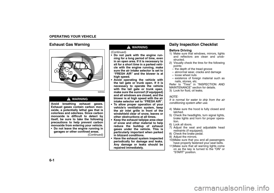
Avoid breathing exhaust gases.
Exhaust gases contain carbon mon-
oxide, a potentially lethal gas that is
colorless and odorless. Since carbon
monoxide is difficult to detect by
itself, be sure to take the following
precautions to help prevent carbon
monoxide from entering your vehicle.
Do not leave the engine running in
garages or other confined areas.
(Continued)
WARNING
(Continued)
Do not park with the engine run-
ning for a long period of time, even
in an open area. If it is necessary to
sit for a short time in a parked vehi-
cle with the engine running, make
sure the air intake selector is set to
“FRESH AIR” and the blower is at
high speed.
Avoid operating the vehicle with
the tail gate or trunk open. If it is
necessary to operate the vehicle
with the tail gate or trunk open,
make sure the sunroof (if equipped)
and all windows are closed, and the
blower is at high speed with the air
intake selector set to “FRESH AIR”.
To allow proper operation of your
vehicle’s ventilation system, keep
the air inlet grille in front of the
windshield clear of snow, leaves or
other obstructions at all times.
Keep the exhaust tailpipe area clear
of snow and other material to help
reduce the buildup of exhaust
gases under the vehicle. This is
particularly important when parked
in blizzard conditions.
Have the exhaust system inspected
periodically for damage and leaks.
Any damage or leaks should be
repaired immediately.
Exhaust Gas Warning: NO
Daily Inspection Checklist: NO
Page 158 of 278
6-3OPERATING YOUR VEHICLE
80J21-03E
Vehicle With Keyless Start System
80JC002
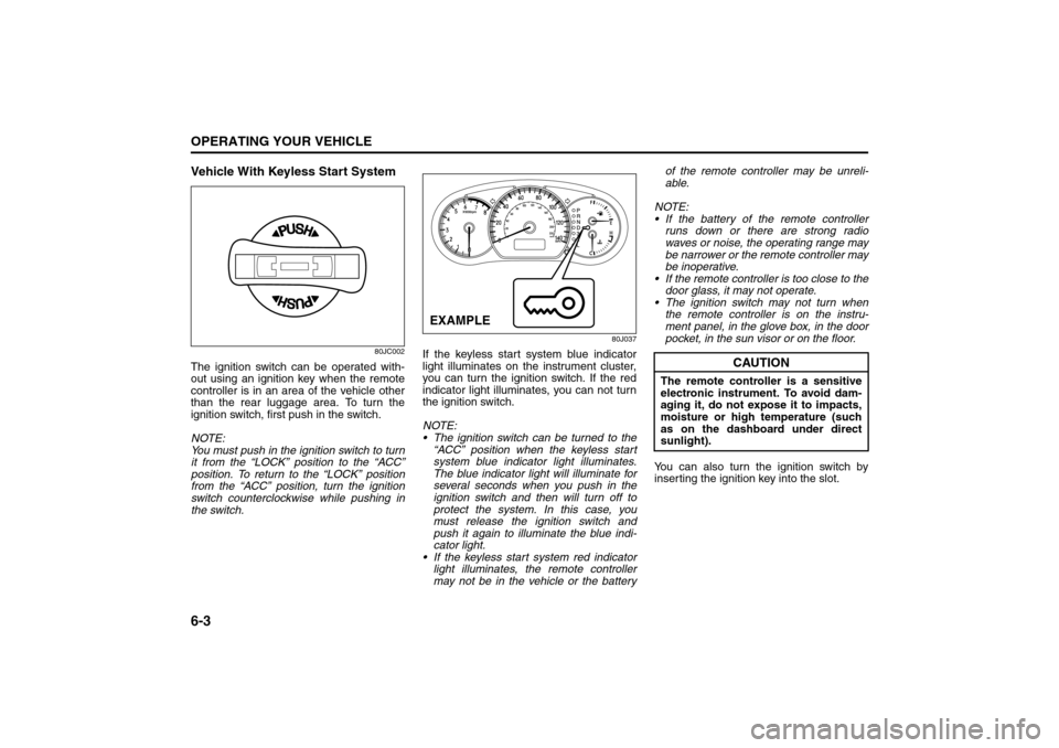
The ignition switch can be operated with-
out using an ignition key when the remote
controller is in an area of the vehicle other
than the rear luggage area. To turn the
ignition switch, first push in the switch.
NOTE:
You must push in the ignition switch to turn
it from the “LOCK” position to the “ACC”
position. To return to the “LOCK” position
from the “ACC” position, turn the ignition
switch counterclockwise while pushing in
the switch.
80J037
If the keyless start system blue indicator
light illuminates on the instrument cluster,
you can turn the ignition switch. If the red
indicator light illuminates, you can not turn
the ignition switch.
NOTE:
The ignition switch can be turned to the
“ACC” position when the keyless start
system blue indicator light illuminates.
The blue indicator light will illuminate for
several seconds when you push in the
ignition switch and then will turn off to
protect the system. In this case, you
must release the ignition switch and
push it again to illuminate the blue indi-
cator light.
If the keyless start system red indicator
light illuminates, the remote controller
may not be in the vehicle or the batteryof the remote controller may be unreli-
able.
NOTE:
If the battery of the remote controller
runs down or there are strong radio
waves or noise, the operating range may
be narrower or the remote controller may
be inoperative.
If the remote controller is too close to the
door glass, it may not operate.
The ignition switch may not turn when
the remote controller is on the instru-
ment panel, in the glove box, in the door
pocket, in the sun visor or on the floor.
You can also turn the ignition switch by
inserting the ignition key into the slot.EXAMPLE
CAUTION
The remote controller is a sensitive
electronic instrument. To avoid dam-
aging it, do not expose it to impacts,
moisture or high temperature (such
as on the dashboard under direct
sunlight).
Engine Block Heater: 1
Page 180 of 278
7-3DRIVING TIPS
80J21-03E
Tire ChainsTire chains should only be used if they are
needed to increase traction or are required
by law. Make sure that the chains you use
are small-link chains or cable-type chains
and are the correct size for your vehicle’s
tires. Also make sure that there is enough
clearance between the fenders and the
chains as installed on the tires.
Install the chains on the front tires tightly,
according to the chain manufacturer’s
instructions. Retighten the chains after
driving about 1.0 km (1/2 mile) if neces-
sary. With the chains installed, drive slowly.Do not drive through deep or rushing
water
Driving in deep or rushing water can be
hazardous. You could lose control of the
vehicle and the occupants could drown.
Also, your vehicle could be seriously dam-
aged. To avoid these risks, observe the fol-
lowing instructions and precautions.
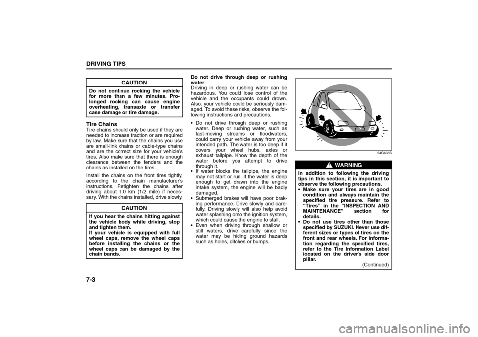
Do not drive through deep or rushing
water. Deep or rushing water, such as
fast-moving streams or floodwaters,
could carry your vehicle away from your
intended path. The water is too deep if it
covers your wheel hubs, axles or
exhaust tailpipe. Know the depth of the
water before you attempt to drive
through it.
If water blocks the tailpipe, the engine
may not start or run. If the water is deep
enough to get drawn into the engine
intake system, the engine will be badly
damaged.
Submerged brakes will have poor brak-
ing performance. Drive slowly and care-
fully. Driving slowly will also help avoid
water splashing onto the ignition system,
which could cause the engine to stall.
Even when driving through shallow or
still waters, drive carefully since the
water may be hiding ground hazards
such as holes, ditches or bumps.
54G638S
CAUTION
Do not continue rocking the vehicle
for more than a few minutes. Pro-
longed rocking can cause engine
overheating, transaxle or transfer
case damage or tire damage.
CAUTION
If you hear the chains hitting against
the vehicle body while driving, stop
and tighten them.
If your vehicle is equipped with full
wheel caps, remove the wheel caps
before installing the chains or the
wheel caps can be damaged by the
chain bands.
WARNING
In addition to following the driving
tips in this section, it is important to
observe the following precautions.
Make sure your tires are in good
condition and always maintain the
specified tire pressure. Refer to
“Tires” in the “INSPECTION AND
MAINTENANCE” section for
details.
Do not use tires other than those
specified by SUZUKI. Never use dif-
ferent sizes or types of tires on the
front and rear wheels. For informa-
tion regarding the specified tires,
refer to the Tire Information Label
located on the driver’s side door
pillar.
(Continued)
Driving on Slippery Roads: NO
Page 215 of 278
9-26
INSPECTION AND MAINTENANCE
80J21-03E
Tire Inflation PressureTire inflation pressure should be checked
when the tire is cold. “Cold tire inflation
pressure” is the pressure in a tire that has
been driven less than 1 mile (1.6 km) or
has been standing for three hours or more.
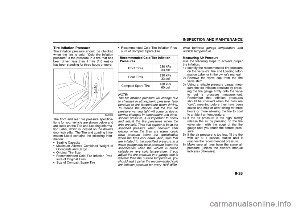
80JS025
The front and rear tire pressure specifica-
tions for your vehicle are shown below and
are listed on the Tire and Loading Informa-
tion Label, which is located on the driver’s
door lock pillar. The Tire and Loading Infor-
mation Label contains the following infor-
mation:
Seating Capacity
Maximum Allowed Combined Weight of
Occupants and Cargo
Original Tire Size
Recommended Cold Tire Inflation Pres-
sure of Original Tires
Size of Compact Spare Tire Recommended Cold Tire Inflation Pres-
sure of Compact Spare Tire
NOTE:
The tire inflation pressure will change due
to changes in atmospheric pressure, tem-
perature or tire temperature when driving.
To reduce the chance that the low tire
pressure warning light will come on due to
normal changes in temperature and atmo-
spheric pressure, it is important to check
and adjust the tire pressures when the
tires are cold. Tires that appear to be at the
specified pressure when checked after
driving, when the tires are warm, could
have pressure below the specification
when the tires cool down. Also, tires that
are inflated to the specified pressure in a
warm garage may have pressure below the
specification when the vehicle is driven
outside in very cold temperature. If you
adjust the tire pressure in a garage that is
warmer than the outside temperature, you
should add 1 psi to the recommended cold
tire inflation pressure for every 10°F differ-ence between garage temperature and
outside temperature.
Measuring Air Pressure
Use the following steps to achieve proper
tire inflation:
1) Identify the recommended tire pressure
on the vehicle’s Tire and Loading Infor-
mation Label or in the owner’s manual.
2) Remove the valve cap from the tire
valve stem.
3) Using a reliable pressure gauge, mea-
sure the tire inflation pressure by press-
ing the tire gauge firmly onto the valve
to get a pressure measurement.
Remember that inflation pressures
should be checked when the tires are
“cold”, meaning before they have been
driven one mile or after sitting for three
hours or more allowing the tire to cool
to ambient air temperature.
4) If the air pressure is too high, slowly
release the air by pressing on the tire
valve stem with the edge of the tire
gauge until you reach the correct pres-
sure.
5) If the air pressure is too low, fill the tire
with air at a service station until it
reaches the recommended pressure.
6) Make sure all tires have the same air
pressure (unless the owner’s manual
indicates otherwise).
Recommended Cold Tire Inflation
Pressures
Fr on t T ir es230 kPa
33 psi
Rear Tires230 kPa
33 psi
Compact Spare Tire420 kPa
60 psi
Tires: 6
Page 225 of 278

9-36
INSPECTION AND MAINTENANCE
80J21-03E
Fuses in the Engine Compartment
80J051
80J052
(1)
(2) (3)
(28) (27) (26) (25) (6) (7) (9) (11)
(15) (16) (17) (18) (19)
(24)
(8) (4) (5) (10)
(22) (21)
(23)(20)(12) (13) (14)
(30)
(29)
MAIN FUSE / PRIMARY FUSE
(1) 80A All electric load
(2) 50APower window, Ignition,
Wiper, Starter
(3) 50ATail light, Rear defogger,
Door lock, Hazard/Horn,
Dome
(4) – Blank
(5) – Blank
(6) 15A Head light (Right) fuse
(7) 15A Head light (Left) fuse
(8) 20A Front fog light fuse
(9) – Blank
(10) 40A ABS control module fuse
(11) 30A Radiator fan fuse
(12) 30A ABS control module fuse
(13) 30A Starting motor fuse
(14) 50A Ignition switch fuse
(15) 30A Blower fan fuse
(16) 20A Air compressor fuse
(17) 15A Throttle motor fuse
(18) 15A Automatic transaxle fuse
(19) 15A Fuel injection fuse
(20) – Automatic transaxle relay
(21) – Air compressor relay
(22) – Fuel pump relay
(23) – Condenser fan relay
(24) – Front fog light relay
(25) – Throttle motor relay
(26) – FI MAIN
(27) – Starting motor relay
(28) – Radiator fan relay
(29) – Radiator fan relay 2
(30) – Radiator fan relay 3
Bulb Replacement: 7
Page 226 of 278
9-37INSPECTION AND MAINTENANCE
80J21-03E
60A243
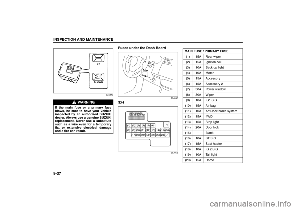
Fuses under the Dash Board
79J093
SX4
80J053
WARNING
If the main fuse or a primary fuse
blows, be sure to have your vehicle
inspected by an authorized SUZUKI
dealer. Always use a genuine SUZUKI
replacement. Never use a substitute
such as a wire even for a temporary
fix, or extensive electrical damage
and a fire can result.
BLOWNOK
(1) (2) (3) (4) (5) (6)
(8) (9) (10) (11) (12) (13) (14) (15) (16)
(18) (17) (19) (20) (21) (22) (23)(7)
MAIN FUSE / PRIMARY FUSE
(1) 15A Rear wiper
(2) 15A Ignition coil
(3) 10A Back-up light
(4) 10A Meter
(5) 15A Accessory
(6) 15A Accessory 2
(7) 30A Power window
(8) 30A Wiper
(9) 10A IG1 SIG
(10) 15A Air bag
(11) 10A Anti-lock brake system
(12) 15A 4WD
(13) 15A Stop light
(14) 20A Door lock
(15) – Blank
(16) 10A ST SIG
(17) 15A Seat heater
(18) 10A IG 2 SIG
(19) 10A Tail light
(20) 15A Dome
Bulb Replacement: 7
Page 227 of 278
9-38
INSPECTION AND MAINTENANCE
80J21-03E
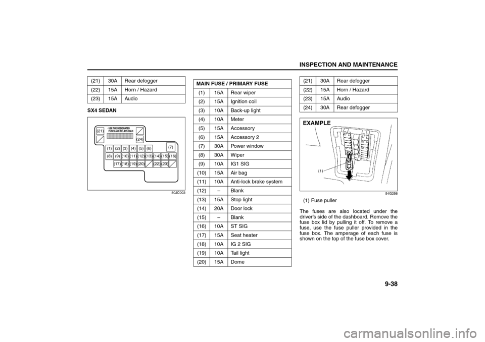
SX4 SEDAN
80JC003
54G256
(1) Fuse puller
The fuses are also located under the
driver’s side of the dashboard. Remove the
fuse box lid by pulling it off. To remove a
fuse, use the fuse puller provided in the
fuse box. The amperage of each fuse is
shown on the top of the fuse box cover. (21) 30A Rear defogger
(22) 15A Horn / Hazard
(23) 15A Audio
(1) (2) (3) (4) (5) (6)
(8) (9) (10) (11) (12) (13)
(21)
(24)
(14) (15) (16)
(18) (17) (19) (20) (22) (23)(7)
MAIN FUSE / PRIMARY FUSE
(1) 15A Rear wiper
(2) 15A Ignition coil
(3) 10A Back-up light
(4) 10A Meter
(5) 15A Accessory
(6) 15A Accessory 2
(7) 30A Power window
(8) 30A Wiper
(9) 10A IG1 SIG
(10) 15A Air bag
(11) 10A Anti-lock brake system
(12) – Blank
(13) 15A Stop light
(14) 20A Door lock
(15) – Blank
(16) 10A ST SIG
(17) 15A Seat heater
(18) 10A IG 2 SIG
(19) 10A Tail light
(20) 15A Dome
(21) 30A Rear defogger
(22) 15A Horn / Hazard
(23) 15A Audio
(24) 30A Rear defoggerEXAMPLE
Bulb Replacement: 7