2008 SUZUKI SX4 brakes
[x] Cancel search: brakesPage 212 of 278
9-23INSPECTION AND MAINTENANCE
80J21-03E
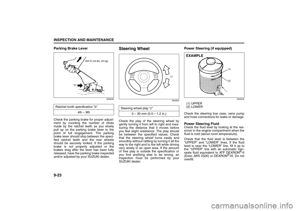
Parking Brake Lever
60A226
Check the parking brake for proper adjust-
ment by counting the number of clicks
made by the ratchet teeth as you slowly
pull up on the parking brake lever to the
point of full engagement. The parking
brake lever should stop between the speci-
fied ratchet teeth and the rear wheels
should be securely locked. If the parking
brake is not properly adjusted or the
brakes drag after the lever has been fully
released, have the parking brake inspected
and/or adjusted by your SUZUKI dealer.
Steering Wheel
80J005
Check the play of the steering wheel by
gently turning it from left to right and mea-
suring the distance that it moves before
you feel slight resistance. The play should
be between the specified values. Check
that the steering wheel turns easily and
smoothly without rattling by turning it all the
way to the right and to the left while driving
very slowly in an open area. If the amount
of free play is outside the specification or
you find anything else to be wrong, an
inspection must be performed by your
SUZUKI dealer.
Power Steering (if equipped)
54G225
(1) UPPER
(2) LOWER
Check the steering box case, vane pump
and hose connections for leaks or damage.Power Steering FluidCheck the fluid level by looking at the res-
ervoir in the engine compartment when the
fluid is cold (about room temperature).
Check that the fluid level is between the
“UPPER” and “LOWER” lines. If the fluid
level is near the “LOWER” line, fill it up to
the “UPPER” line with an automatic tran-
saxle fluid equivalent to ATF DEXRON
®-II
(Esso JWS 2326) or DEXRON
®-III. Do not
overfill. Ratchet tooth specification “b”
4th – 9th
200 N (44 lbs, 20 kg)
“b”
Steering wheel play “c”
0 – 30 mm (0.0 – 1.2 in.)
“c”
EXAMPLE
Tires: 6
Page 221 of 278
9-32
INSPECTION AND MAINTENANCE
80J21-03E
GLOSSARY OF TIRE TERMINOL-
OGYAccessory Weight – the combined weight
(in excess of those standard items which
may be replaced) of automatic transaxle,
power steering, power brakes, power win-
dows, power seats, radio, and heater, to
the extent that these items are available as
factory-installed equipment (whether
installed or not).
Cold Tire Inflation Pressure – the pressure
in a tire that has been driven less than 1
mile or has been standing for three hours
or more.
Curb Weight – the weight of a motor vehi-
cle with standard equipment including the
maximum capacity of fuel, oil, and coolant,
and, if so equipped, air conditioning and
additional weight optional engine.
Intended Outboard Sidewall – (1) the side-
wall that contains a whitewall, bears white
lettering or bears manufacturer, brand,
and/or model name molding that is higher
or deeper than the same molding on the
other sidewall of the tire, or (2) the outward
facing sidewall of an asymmetrical tire that
has a particular side that must always face
outward when mounted on a vehicle.
Maximum Inflation Pressure – the maxi-
mum cold inflation pressure a tire is
designed to support in normal service.Maximum Loaded Vehicle Weight – the
sum of curb weight, accessory weight,
vehicle capacity weight (total load capac-
ity), and production options weight.
Normal Occupant Weight – 68 kilograms
times the number of occupants specified in
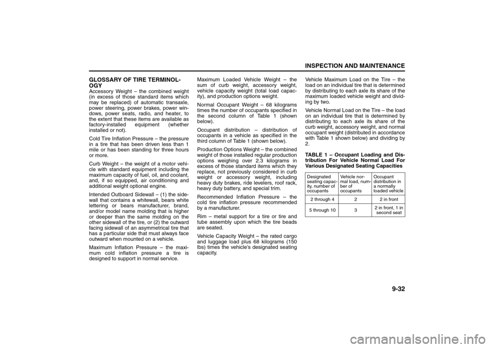
the second column of Table 1 (shown
below).
Occupant distribution – distribution of
occupants in a vehicle as specified in the
third column of Table 1 (shown below).
Production Options Weight – the combined
weight of those installed regular production
options weighing over 2.3 kilograms in
excess of those standard items which they
replace, not previously considered in curb
weight or accessory weight, including
heavy duty brakes, ride levelers, roof rack,
heavy duty battery, and special trim.
Recommended Inflation Pressure – the
cold tire inflation pressure recommended
by a manufacturer.
Rim – metal support for a tire or tire and
tube assembly upon which the tire beads
are seated.
Vehicle Capacity Weight – the rated cargo
and luggage load plus 68 kilograms (150
lbs) times the vehicle’s designated seating
capacity.Vehicle Maximum Load on the Tire – the
load on an individual tire that is determined
by distributing to each axle its share of the
maximum loaded vehicle weight and divid-
ing by two.
Vehicle Normal Load on the Tire – the load
on an individual tire that is determined by
distributing to each axle its share of the
curb weight, accessory weight, and normal
occupant weight (distributed in accordance
with Table 1 shown below) and dividing by
2.
TABLE 1 – Occupant Loading and Dis-
tribution For Vehicle Normal Load For
Various Designated Seating Capacities
Designated
seating capac-
ity, number of
occupantsVehicle nor-
mal load, num-
ber of
occupantsOccupant
distribution in
a normally
loaded vehicle
2 through 4 2 2 in front
5 through 10 32 in front, 1 in
second seat
Fuses: 7
Page 242 of 278
10-3EMERGENCY SERVICE
80J21-03E
Jump Starting Instructions
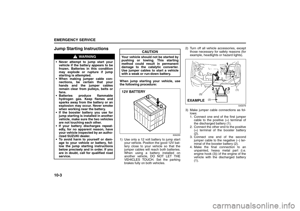
When jump starting your vehicle, use
the following procedure:
60A269
1) Use only a 12 volt battery to jump start
your vehicle. Position the good 12V bat-
tery close to your vehicle so that the
jumper cables will reach both batteries.
When using a battery installed on
another vehicle, DO NOT LET THE
VEHICLES TOUCH. Set the parking
brakes fully on both vehicles.2) Turn off all vehicle accessories, except
those necessary for safety reasons (for
example, headlights or hazard lights).
54G079
3) Make jumper cable connections as fol-
lows:
1. Connect one end of the first jumper
cable to the positive (+) terminal of
the discharged battery (1).
2. Connect the other end to the positive
(+) terminal of the booster battery
(2).
3. Connect one end of the second
jumper cable to the negative (–) ter-
minal of the booster battery (2).
4. Make the final connection to an
unpainted, heavy metal part (i.e.
engine hook (3)) of the engine of the
vehicle with the discharged battery
(1).
WARNING
Never attempt to jump start your
vehicle if the battery appears to be
frozen. Batteries in this condition
may explode or rupture if jump
starting is attempted.
When making jumper cable con-
nections, be certain that your
hands and the jumper cables
remain clear from pulleys, belts or
fans.
Batteries produce flammable
hydrogen gas. Keep flames and
sparks away from the battery or an
explosion may occur. Never smoke
when working near the battery.
If the booster battery you use for
jump starting is installed in another
vehicle, make sure the two vehicles
are not touching each other.
If your battery discharges repeat-
edly, for no apparent reason, have
your vehicle inspected by an autho-
rized SUZUKI dealer.
To avoid harm to yourself or dam-
age to your vehicle or battery, fol-
low the jump starting instructions
below precisely and in order. If you
are in doubt, call for qualified road
service.
CAUTION
Your vehicle should not be started by
pushing or towing. This starting
method could result in permanent
damage to the catalytic converter.
Use jumper cables to start a vehicle
with a weak or run-down battery.12V BATTERY
(1)
(3)
(2)
EXAMPLE
Jacking Instructions: 5
Page 251 of 278
11-4
APPEARANCE CARE
80J21-03E
WashingWhen washing the vehicle, follow the
instructions below:
1) Flush the underside of body and wheel
housings with pressurized water to
remove mud and debris. Use plenty of
water.2) Rinse the body to loosen the dirt.
Remove dirt and mud from the body
exterior with running water. You may
use a soft sponge or brush. Do not use
hard materials which can scratch the
paint or plastic. Remember that the
headlight covers or lenses are made of
plastic in many cases.
3) Wash the entire exterior with a mild
detergent or car wash soap using a
sponge or soft cloth. The sponge or
cloth should be frequently soaked in the
soap solution.
4) Once the dirt has been completely
removed, rinse off the detergent with
running water.
5) After rinsing, wipe off the vehicle body
with a wet chamois or cloth and allow it
to dry in the shade.6) Check carefully for damage to painted
surfaces. If there is any damage,
“touch-up” the damage following the
procedure below:
1. Clean all damaged spots and allow
them to dry.
2. Stir the paint and “touch-up” the
damaged spots lightly using a small
brush.
3. Allow the paint to dry completely.
WARNING
Never attempt to wash and wax
your vehicle with the engine run-
ning.
When cleaning the underside of the
body and fender, where there may
be sharp-edged parts, you should
wear gloves and a long-sleeved
shirt to protect your hands and
arms from being cut.
After washing your vehicle, care-
fully test the brakes before driving
to make sure they have maintained
their normal effectiveness.
CAUTION
When washing the vehicle, avoid
directing steam or hot water of
more than 80°C (176°F) on plastic
parts.
To avoid damaging engine compo-
nents, do not use pressurized
water in the engine compartment.
CAUTION
To avoid damage to the paint or plas-
tic surface, do not wipe the dirt off
without ample water. Be sure to fol-
low above procedure.
CAUTION
When using a commercial car wash
product, observe the cautions speci-
fied by the manufacturer. Never use
strong household detergents or
soaps.
CAUTION
If you use an automatic car wash,
make sure that your vehicle’s body
parts, such as spoilers, can not be
damaged. If you are in doubt, consult
the car wash operator for advice.
Vehicle Cleaning:
Page 256 of 278
12-3GENERAL INFORMATION
80J21-03E
On-Board Vehicle Computers
and Event Data RecordersYour vehicle is equipped with on-board
computer systems which monitor and
control several aspects of vehicle per-
formance, including the following:
Emission-related components and
engine parameters such as engine
speed and throttle position are moni-
tored to provide emissions control
and to provide optimum fuel econ-
omy. Your vehicle also has an on-
board diagnostic system which mon-
itors and records information about
emission-related malfunctions.
Signals from various sensors are
monitored to provide air bag deploy-
ment.
If your vehicle is equipped with
antilock brakes, conditions such as
vehicle speed and brake perfor-
mance are monitored, so that the
ABS system can provide effective
antilock braking. If your vehicle has
an Electronic Stability Program
(ESP
®) system, conditions such as
yaw rate, lateral acceleration, and
brake fluid pressure are monitored,
so that the ESP
® system can help
the driver control the vehicle in diffi-
cult driving situations.
Some information may be stored by
the on-board computers during normaloperation of the vehicle. This stored
information can assist technicians in
repairing the vehicle when malfunc-
tions occur. Other information is stored
only in the event of crash, by computer
systems that are commonly called
Event Data Recorders (EDRs).
In a crash event, EDRs such as the
Airbag Sensing and Diagnostic Mod-
ule (SDM) in your vehicle may record
information about the condition of the
vehicle and how it was operated, such
as data related to airbag readiness,
airbag performance, safety belt usage,
and the severity of the collision. These
data can help provide a better under-
standing of the circumstances in which
crashes and injuries occur and lead to
the designing of safer vehicles. The
SDM in your vehicle does not collect
or store personal information.
To read the stored information, special
equipment is needed and access to
the vehicle or storage device is
required. SUZUKI will not access infor-
mation about a crash event or share it
with others other than with the consent
of the vehicle owner or lessee, in
response to an official request from
the police or similar government office,
as part of SUZUKI’s defense of litiga-
tion through the discovery process, or
as required by law.In addition, once SUZUKI collects or
receives data, SUZUKI may use the
data for research conducted by
SUZUKI, make the data available for
outside research if need is shown and
confidentiality is assured, or make
summary data which does not identify
specific vehicles available for outside
research.
Others, such as law enforcement per-
sonnel, may have access to the spe-
cial equipment that can read the
information if they have access to the
vehicle or storage device.
Reporting Safety Defects: NO
Page 271 of 278
15-1
INDEX
15
80J21-03E
INDEXSymbols“CRUISE” Indicator Light...................................................... 4-8
“ESP OFF” Indicator Light ........................................... 4-6, 6-14
“ESP OFF” Switch ............................................................... 4-13
“ESP” (Electronic Stability Program) Warning Light ......... 4-5
“ESP” Warning Light ........................................................... 6-13
“PASS AIRBAG OFF” Indicator .......................................... 4-20
“SET” Indicator Light ............................................................ 4-8Numerics2WD/i-AWD (intelligent All Wheel Drive) Switch ............... 4-14
4-Speed Automatic Transaxle .............................................. 6-5AA/T Selector Position Indicator .......................................... 4-10
Accelerator Pedal .................................................................. 5-2
Accessory Socket ................................................................ 5-11
Adding Coolant .................................................................... 9-18
Adjusting Seat Position ...................................................... 2-20
Adjusting Seatbacks ........................................................... 2-20
AIR BAG Light ........................................................................ 4-7
Air Cleaner............................................................................ 9-19
Air Conditioning System ..................................................... 9-48
All Seat Belts ........................................................................ 2-25
Anti-Lock Brake System (ABS) .......................................... 6-10
Anti-Lock Brake System (ABS) Warning Light ................... 4-5
Anti-Lock Braking System (ABS) ....................................... 6-12
Assist Grips............................................................................ 5-9
Audio Systems ..................................................................... 4-32
Automatic Heating and Air Conditioning System
(Climate Control).................................................................. 4-28Automatic Locking Retractor (ALR) ................................... 2-24
Automatic Transaxle Fluid .................................................. 9-16
BBasic Operations.................................................................. 4-35
Battery ................................................................................... 9-35
Brake Assist System............................................................ 6-10
Brake Fluid............................................................................ 9-21
Brake Pedal.................................................................... 5-2, 9-22
Brake System Warning Light ................................................ 4-4
Brakes ................................................................................... 9-21
Braking .................................................................................... 6-9
Break-In ................................................................................. 6-18
Bulb Replacement ................................................................ 9-39CCatalytic Converter .............................................................. 6-19
Changing Engine Oil and Filter........................................... 9-12
Changing Wheels ................................................................. 9-31
Charging Light........................................................................ 4-6
Child Lock System (rear doors) .......................................... 2-13
Child Restraint Systems ...................................................... 2-29
Cigarette Lighter and Ashtray............................................. 4-16
Clock ..................................................................................... 4-17
Clutch Pedal .................................................................. 5-2, 9-24
Compact Spare Tire ............................................................. 9-30
Coolant Level Check ............................................................ 9-18
Coolant Replacement .......................................................... 9-18
Corrosion Prevention .......................................................... 11-1
Cruise Control ........................................................................ 3-9
Cup Holder and Storage Area ............................................. 5-11DDaily Inspection Checklist..................................................... 6-1
Page 274 of 278

15-4INDEX
80J21-03E
Periodic Maintenance Schedule ........................................... 9-3
Power Assisted Brakes ......................................................... 6-9
Power Door Locking System ................................................ 2-2
Power Mirror Control ........................................................... 2-19
Power Steering..................................................................... 9-23
Power Steering Fluid ........................................................... 9-23
Power Window Controls ..................................................... 2-16RRadio Antenna ............................................................ 4-38, 5-16
Rear Window Wiper/Washer Switch .................................... 3-8
Refill with Oil and Check for Leaks .................................... 9-13
Refilling................................................................................. 9-12
Remote Audio Controls.............................................. 3-11, 4-53
Replace the Oil Filter ........................................................... 9-13
Replacing Tires and/or Wheels .......................................... 6-18
Reporting Safety Defects .................................................... 12-4
Roof Rails or Roof Rack Anchors ...................................... 5-16SSafety Certification Label.................................................... 12-2
Seat Adjustment .................................................................. 2-19
Seat Belt Extender ............................................................... 2-38
Seat Belt Hanger .................................................................. 2-28
Seat Belt Inspection ............................................................ 2-29
Seat Belt Pretensioner System........................................... 2-39
Seat Belt Reminder .............................................................. 2-26
Seat Belts and Child Restraint Systems............................ 2-22
Selection of Coolant ............................................................ 9-17
Shoulder Anchor Height Adjuster ...................................... 2-28
Side Air Bags and Side Curtain Air Bags .......................... 2-43
Side Door Locks .................................................................... 2-1
SLIP Indicator Light ...................................................... 4-5, 6-13Snow Tires ............................................................................ 9-31
Spark Plugs .......................................................................... 9-20
SPECIFICATIONS ................................................................. 14-1
Specified Fluid...................................................................... 9-16
Specified Gear Oil ................................................................ 9-14
Specified Oil ......................................................................... 9-11
Speedometer ........................................................................ 4-11
Spot Light ............................................................................... 5-9
Stability Control System...................................................... 6-12
Starting the Engine ................................................................ 6-2
Steering Wheel ..................................................................... 9-23
Sun Visor ................................................................................ 5-8
Supplemental Restraint System (air bags) ........................ 2-40
TTachometer ........................................................................... 4-12
Tailgate.................................................................................. 2-14
Temperature Gauge ............................................................. 4-13
Theft Deterrent Light............................................................ 4-20
Thermometer ........................................................................ 4-17
Tilt Steering Lock Lever ........................................................ 3-8
Tire Chains.............................................................................. 7-3
Tire Changing Tool .............................................................. 5-13
Tire Inflation Pressure ......................................................... 9-26
Tire Inspection...................................................................... 9-27
Tire Pressure Monitoring System (TPMS) ......................... 6-14
Tire Rotation ......................................................................... 9-29
Tire Sidewall Labeling ......................................................... 9-24
Tire Size ................................................................................ 9-25
Tires....................................................................................... 9-24
Towing a Disabled Vehicle .................................................. 10-4
Towing Your Vehicle (recreational towing) ......................... 8-2