2008 SUZUKI SX4 coolant
[x] Cancel search: coolantPage 196 of 278

9-7INSPECTION AND MAINTENANCE
80J21-03E
Maintenance Recommended under Severe Driving ConditionsFollow this schedule if your car is mainly operated under one or more of the following conditions:
When most trips are less than 6 kilometers (4 miles)
When most trips are less than 16 kilometers (10 miles) and outside temperature remain below freezing.
Idling and/or low-speed operation in stop-and-go traffic.
Operating in dusty areas.
Schedule should also be followed if the car is used for delivery service, police, taxi or other commercial applications.
R: Replace or change
I : Inspect, clean, adjust, lubricate or replace as necessaryInterval: This interval should be judged by odometer
reading or months, whichever comes first.miles (x 1000) 3 6 9 12 15 18 21 24 27 30 33 36 39
km (x 1000) 5 101520253035404550556065
months 3 6 9 12 15 18 21 24 27 30 33 36 39ENGINE & EMISSION CONTROL
1. Drive belt
*Tension check, *adjustment, *replacement
–
–
–
–
–
–
–
–
–
I
–
–
–
*2.Valve lash (clearance) ––––––––– I –––
3.Engine oil and oil filter
R
R
R
R
R
R
R
R
R
R
R
R
R
*4. Cooling system hoses and connections–––– I –––– I –––
5.Engine coolant
–
–
–
–
–
–
–
–
–
R
–
–
–
*6. Exhaust pipes and mountings–––– I –––– I –––
*7.
EVAP canister
Replace every 250000 km (150000 miles) or 180 months
*8.Emission-related hoses & tubes –––––––––––––
9.Spark plugs
–
–
–
–
–
–
–
–
–
–
–
–
–
*10.Ignition coil (plug cap) ––––––––– I –––
*11.
Fuel tank & cap
–
–
–
–
I
–
–
–
–
I
–
–
–
12. Air cleaner filter element (paved road)IIIIIIIIIRIII
*13.
Fuel filter
Replace every 250000 km (150000 miles) or 150 months
*14. Fuel lines and connections–––– I –––– I –––
*15.
Canister air suction filter
–
–
–
–
–
–
–
–
–
–
–
–
–
Engine Oil and Filter: 1, 2
Page 197 of 278

9-8
INSPECTION AND MAINTENANCE
80J21-03E
R: Replace or change
I : Inspect, clean, adjust, lubricate or replace as necessaryInterval: This interval should be judged by odometer
reading or months, whichever comes first.miles (x 1000) 42 45 48 51 54 57 60 63 66 69 72 75
km (x 1000) 70 75 80 85 90 95 100 105 110 115 120 125
months 42 45 48 51 54 57 60 63 66 69 72 75ENGINE & EMISSION CONTROL
1. Drive belt
*Tension check, *adjustment, *replacement
–
–
–
–
–
–
I
–
–
–
–
–
*2.Valve lash (clearance) –––––– I –––––
3.Engine oil and oil filter
R
R
R
R
R
R
R
R
R
R
R
R
*4. Cooling system hoses and connections – I–––– I –––– I
5.Engine coolant
–
–
–
–
–
–
R
–
–
–
–
–
*6. Exhaust pipes and mountings – I–––– I –––– I
*7.
EVAP canister
Replace every 250000 km (150000 miles) or 180 months
*8.Emission-related hoses & tubes –––––– I –––––
9.Spark plugs
–
–
–
–
–
–
R
–
–
–
–
–
*10.Ignition coil (plug cap) –––––– I –––––
*11.
Fuel tank & cap
–
I
–
–
–
–
I
–
–
–
–
I
12. Air cleaner filter element (paved road)IIIIIIRIIIII
*13.
Fuel filter
Replace every 250000 km (150000 miles) or 150 months
*14. Fuel lines and connections – I–––– I –––– I
*15.
Canister air suction filter
–
–
–
–
–
–
–
–
–
–
–
R
Engine Oil and Filter: 1, 2
Page 202 of 278

9-13INSPECTION AND MAINTENANCE
80J21-03E
Replace the Oil Filter
60A198
1) Remove the engine under cover.
2) Using an oil filter wrench, turn the oil fil-
ter counterclockwise and remove it.
3) Using a clean rag, wipe off the mount-
ing surface on the engine where the
new filter will be seated.
4) Smear a little engine oil around the rub-
ber gasket of the new oil filter.
5) Screw on the new filter by hand until the
filter gasket contacts the mounting sur-
face.
54G093
(1) Oil filter
(2) 3/4 turn
6) Tighten the filter 3/4 turn from the point
of contact with the mounting surface (or
to the specified torque) using an oil filter
wrench.
Refill with Oil and Check for Leaks1) Pour oil through the filler hole and
install the filler cap.
For the approximate capacity of the oil,
refer to the “Capacities” item in the
“SPECIFICATIONS” section.
2) Start the engine and look carefully for
leaks at the oil filter and drain plug. Run
the engine at various speeds for at least
5 minutes.
3) Stop the engine and wait about 5 min-
utes. Check the oil level again and add
oil if necessary. Check for leaks again.
CAUTION
To tighten the oil filter properly, it is
important to accurately identify the
position at which the filter gasket
first contacts the mounting surface.
Tightening torque specification
14 Nm (10.0 lb-ft, 1.4 kg-m)
CAUTION
To prevent oil leakage, make sure
that the oil filter is tight, but do not
overtighten it.
CAUTION
When replacing the oil filter, it is rec-
ommended that you use a genuine
SUZUKI replacement filter. If you use
an after-market filter, make sure it is
of equivalent quality and carefully fol-
low the manufacturer’s instructions
and precautions.
Automatic Transaxle Fluid: 10
Engine Coolant: 1, 2
Page 203 of 278

9-14
INSPECTION AND MAINTENANCE
80J21-03E
80J014
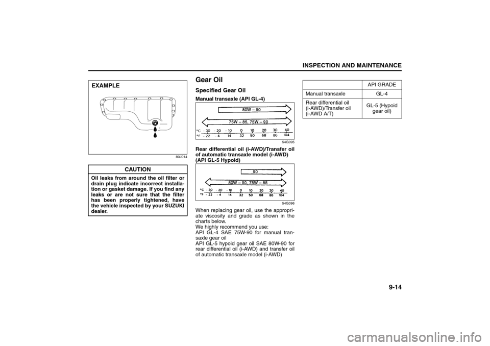
Gear OilSpecified Gear OilManual transaxle (API GL-4)
54G095
Rear differential oil (i-AWD)/Transfer oil
of automatic transaxle model (i-AWD)
(API GL-5 Hypoid)
54G096
When replacing gear oil, use the appropri-
ate viscosity and grade as shown in the
charts below.
We highly recommend you use:
API GL-4 SAE 75W-90 for manual tran-
saxle gear oil
API GL-5 hypoid gear oil SAE 80W-90 for
rear differential oil (i-AWD) and transfer oil
of automatic transaxle model (i-AWD)
CAUTION
Oil leaks from around the oil filter or
drain plug indicate incorrect installa-
tion or gasket damage. If you find any
leaks or are not sure that the filter
has been properly tightened, have
the vehicle inspected by your SUZUKI
dealer.EXAMPLE
API GRADE
Manual transaxle GL-4
Rear differential oil
(i-AWD)/Transfer oil
(i-AWD A/T)GL-5 (Hypoid
gear oil)
Engine Coolant: 1, 2
Page 204 of 278

9-15INSPECTION AND MAINTENANCE
80J21-03E
Manual transaxle
54G097
Transfer case (i-AWD)
80J007
(1) Oil filler and level plugRear differential (i-AWD)
80J015
(1) Oil filler and level plug
Tightening torque
Gear Oil Level CheckThe manual transaxle, transfer gears (i-
AWD A/T) and rear differential (i-AWD) are
lubricated with gear oil. To check the gear
oil level in any of the above locations, use
the following procedure:
1) Park the vehicle on a level surface. Set
parking brake and stop the engine.
2) Remove the oil filler plug (1).
3) Check the inside of the hole with your
finger. If the oil level comes up to the
bottom of the plug hole, the oil level is
correct. If so, reinstall the plug.
4) If the oil level is low, add gear oil
through the filler plug hole (1) until the
oil level reaches the bottom of the filler
hole.Gear Oil ReplacementSince special procedures, materials and
tools are required to change the automatic
transaxle oil, it is recommended that you
trust this job to your authorized SUZUKI
dealer.
(1)
Oil Filler Plug
Manual transaxle21 Nm
(15.2 lb-ft)
(2.1 kg-m)
Transfer 23 Nm
(16.6 lb-ft)
(2.3 kg-m) Rear differential
(1)
Engine Coolant: 1, 2
Windshield Washer Fluid: 3
Page 206 of 278

9-17INSPECTION AND MAINTENANCE
80J21-03E
Changing OilSince special procedures, materials and
tools are required to change the automatic
transaxle oil, it is recommended that you
trust this job to your authorized SUZUKI
dealer.
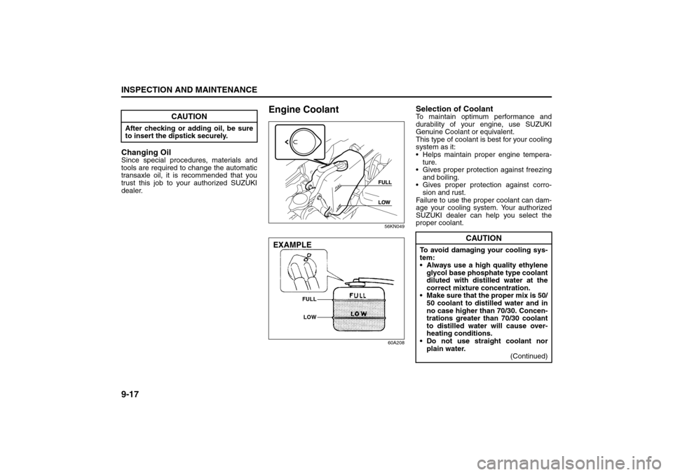
Engine Coolant
56KN049
60A208
Selection of CoolantTo maintain optimum performance and
durability of your engine, use SUZUKI
Genuine Coolant or equivalent.
This type of coolant is best for your cooling
system as it:
Helps maintain proper engine tempera-
ture.
Gives proper protection against freezing
and boiling.
Gives proper protection against corro-
sion and rust.
Failure to use the proper coolant can dam-
age your cooling system. Your authorized
SUZUKI dealer can help you select the
proper coolant.
CAUTION
After checking or adding oil, be sure
to insert the dipstick securely.
EXAMPLE
FULL
LOW
CAUTION
To avoid damaging your cooling sys-
tem:
Always use a high quality ethylene
glycol base phosphate type coolant
diluted with distilled water at the
correct mixture concentration.
Make sure that the proper mix is 50/
50 coolant to distilled water and in
no case higher than 70/30. Concen-
trations greater than 70/30 coolant
to distilled water will cause over-
heating conditions.
Do not use straight coolant nor
plain water.
(Continued)
Spark Plugs: 1, 2
Page 207 of 278

9-18
INSPECTION AND MAINTENANCE
80J21-03E
Coolant Level CheckCheck the engine coolant level at the
reserve tank, not at the radiator. With the
engine cool, the engine coolant level
should be between the “FULL” and “LOW”
marks.Adding CoolantIf the engine coolant level is below the
“LOW” mark, more engine coolant should
be added. Remove the reserve tank cap
and add engine coolant until the reserve
tank level reaches the “FULL” mark. Never
fill the reserve tank above the “FULL” mark.
Coolant ReplacementSince special procedures are required, we
recommend you take your vehicle to your
SUZUKI dealer for coolant replacement.
CAUTION
(Continued)
Do not add extra inhibitors or addi-
tives. They may not be compatible
with your cooling system.
Do not mix different types of base
coolants. Doing so may result in
accelerated seal wear and/or the
possibility of severe overheating
and extensive engine/automatic
transaxle damage.
CAUTION
The mixture you use should con-
tain 50% concentration of anti-
freeze.
If the lowest ambient temperature
in your area is expected to be –
35°C (–31°F) or below, use higher
concentrations up to 60% following
the instructions on the antifreeze
container.
When putting the cap on the reser-
voir tank, line up the arrow on the
cap and the arrow on the tank. Fail-
ure to follow this can result in cool-
ant leakage.
WARNING
Engine coolant is harmful or fatal if
swallowed or inhaled. Do not drink
antifreeze or coolant solution. If swal-
lowed, do not induce vomiting. Imme-
diately contact a poison control
center or a physician. Avoid inhaling
mist or hot vapors; if inhaled, remove
to fresh air. If coolant gets in eyes,
flush eyes with water and seek medi-
cal attention. Wash thoroughly after
handling. Solution can be poisonous
to animals. Keep out of the reach of
children and animals.
Brakes: 6
Page 221 of 278

9-32
INSPECTION AND MAINTENANCE
80J21-03E
GLOSSARY OF TIRE TERMINOL-
OGYAccessory Weight – the combined weight
(in excess of those standard items which
may be replaced) of automatic transaxle,
power steering, power brakes, power win-
dows, power seats, radio, and heater, to
the extent that these items are available as
factory-installed equipment (whether
installed or not).
Cold Tire Inflation Pressure – the pressure
in a tire that has been driven less than 1
mile or has been standing for three hours
or more.
Curb Weight – the weight of a motor vehi-
cle with standard equipment including the
maximum capacity of fuel, oil, and coolant,
and, if so equipped, air conditioning and
additional weight optional engine.
Intended Outboard Sidewall – (1) the side-
wall that contains a whitewall, bears white
lettering or bears manufacturer, brand,
and/or model name molding that is higher
or deeper than the same molding on the
other sidewall of the tire, or (2) the outward
facing sidewall of an asymmetrical tire that
has a particular side that must always face
outward when mounted on a vehicle.
Maximum Inflation Pressure – the maxi-
mum cold inflation pressure a tire is
designed to support in normal service.Maximum Loaded Vehicle Weight – the
sum of curb weight, accessory weight,
vehicle capacity weight (total load capac-
ity), and production options weight.
Normal Occupant Weight – 68 kilograms
times the number of occupants specified in
the second column of Table 1 (shown
below).
Occupant distribution – distribution of
occupants in a vehicle as specified in the
third column of Table 1 (shown below).
Production Options Weight – the combined
weight of those installed regular production
options weighing over 2.3 kilograms in
excess of those standard items which they
replace, not previously considered in curb
weight or accessory weight, including
heavy duty brakes, ride levelers, roof rack,
heavy duty battery, and special trim.
Recommended Inflation Pressure – the
cold tire inflation pressure recommended
by a manufacturer.
Rim – metal support for a tire or tire and
tube assembly upon which the tire beads
are seated.
Vehicle Capacity Weight – the rated cargo
and luggage load plus 68 kilograms (150
lbs) times the vehicle’s designated seating
capacity.Vehicle Maximum Load on the Tire – the
load on an individual tire that is determined
by distributing to each axle its share of the
maximum loaded vehicle weight and divid-
ing by two.
Vehicle Normal Load on the Tire – the load
on an individual tire that is determined by
distributing to each axle its share of the
curb weight, accessory weight, and normal
occupant weight (distributed in accordance
with Table 1 shown below) and dividing by
2.
TABLE 1 – Occupant Loading and Dis-
tribution For Vehicle Normal Load For
Various Designated Seating Capacities
Designated
seating capac-
ity, number of
occupantsVehicle nor-
mal load, num-
ber of
occupantsOccupant
distribution in
a normally
loaded vehicle
2 through 4 2 2 in front
5 through 10 32 in front, 1 in
second seat
Fuses: 7