Page 1352 of 1496
Downloaded from www.Manualslib.com manuals search engine 9F-6 Security and Locks:
Repair Instructions
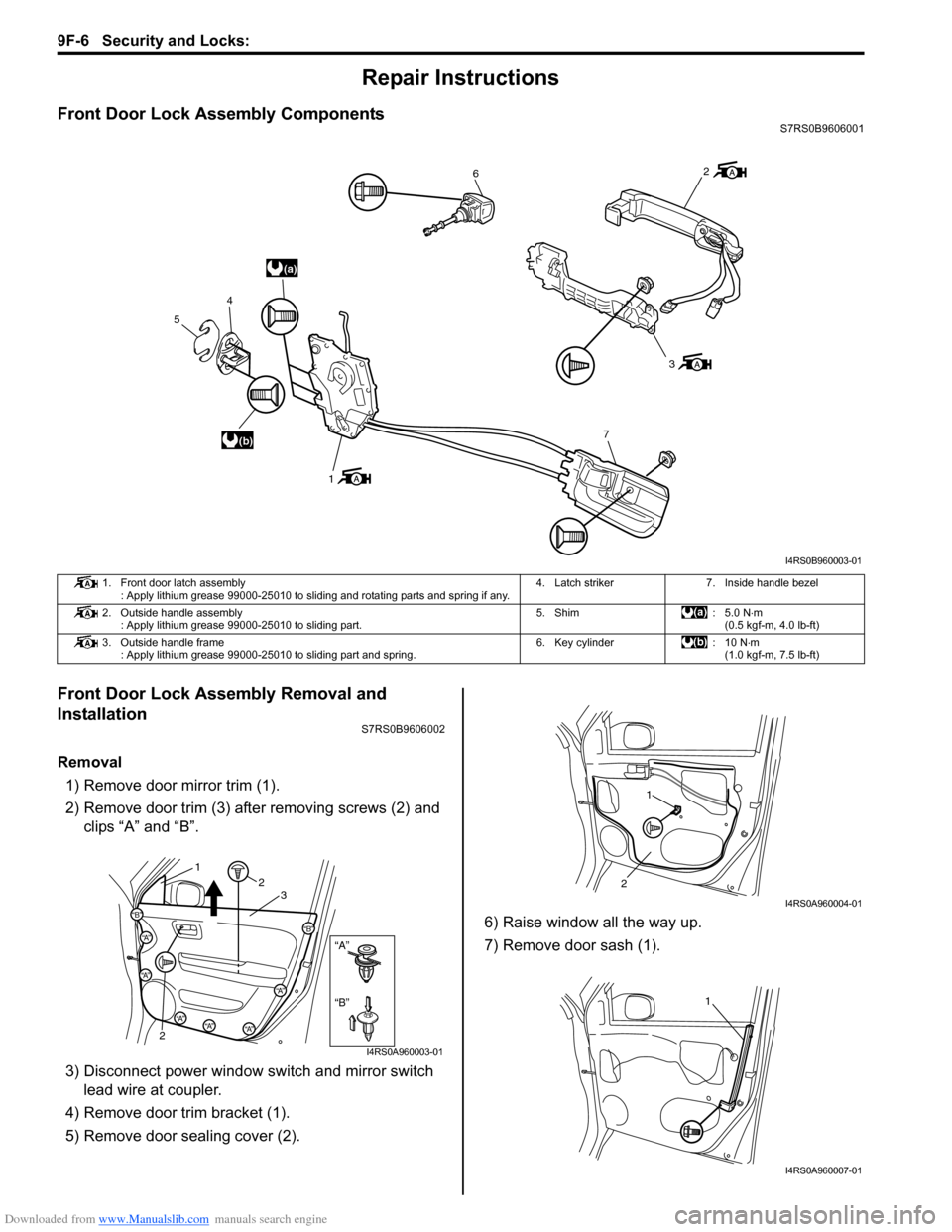
Front Door Lock Assembly ComponentsS7RS0B9606001
Front Door Lock Assembly Removal and
Installation
S7RS0B9606002
Removal1) Remove door mirror trim (1).
2) Remove door trim (3) after removing screws (2) and clips “A” and “B”.
3) Disconnect power window s witch and mirror switch
lead wire at coupler.
4) Remove door trim bracket (1).
5) Remove door sealing cover (2). 6) Raise window all the way up.
7) Remove door sash (1).
(a)
(b)
6
3
7
1
4
5
2
I4RS0B960003-01
1. Front door latch assembly : Apply lithium grease 99000-25010 to sliding and rotating parts and spring if any. 4. Latch striker 7. Inside handle bezel
2. Outside handle assembly : Apply lithium grease 99000-25010 to sliding part. 5. Shim : 5.0 N
⋅m
(0.5 kgf-m, 4.0 lb-ft)
3. Outside handle frame : Apply lithium grease 99000-25010 to sliding part and spring. 6. Key cylinder : 10 N⋅m
(1.0 kgf-m, 7.5 lb-ft)
“B”
“A”
“B”
“A”
“B”“A”
“A”
“A”“A”“A”
12
2 3
I4RS0A960003-01
1
2
I4RS0A960004-01
1
I4RS0A960007-01
Page 1353 of 1496
Downloaded from www.Manualslib.com manuals search engine Security and Locks: 9F-7
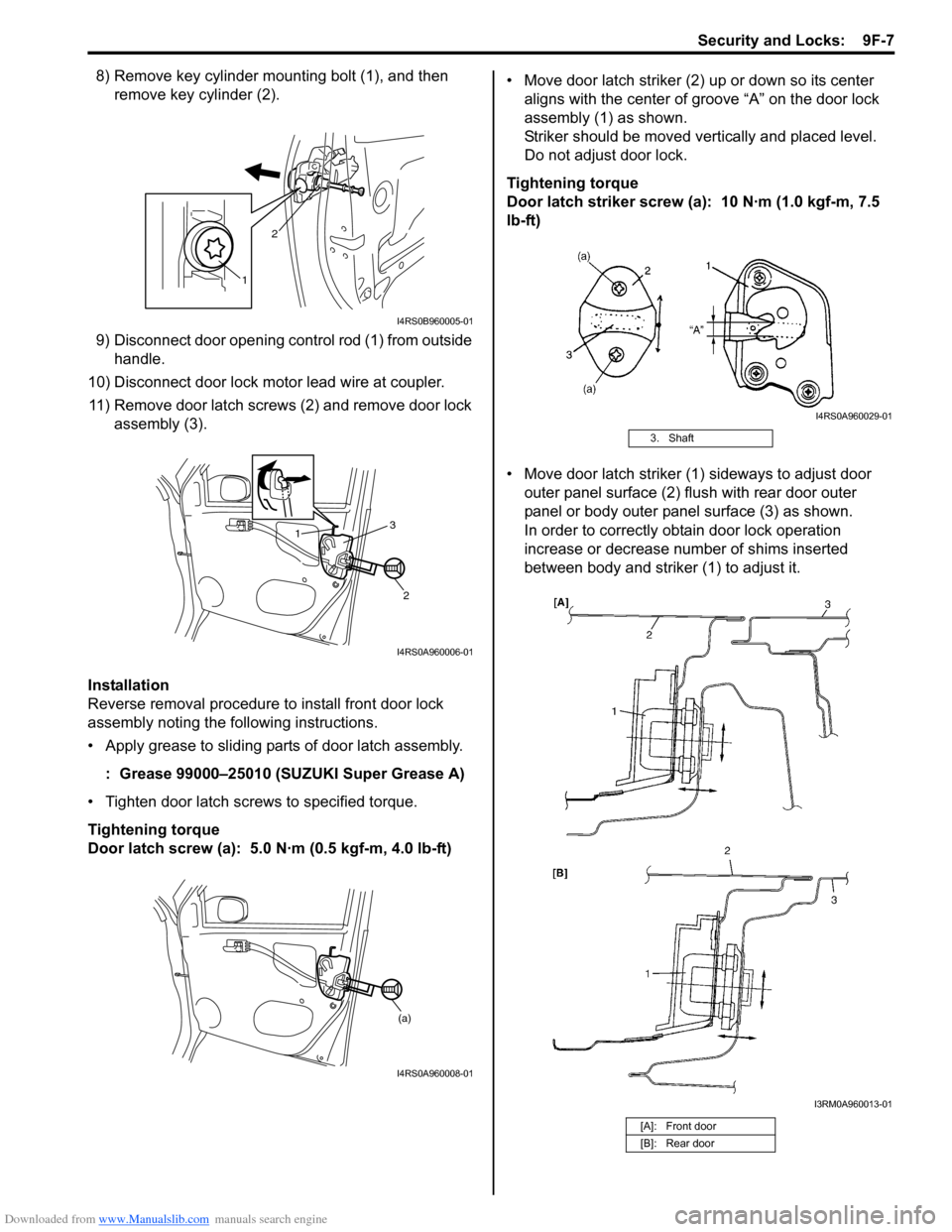
8) Remove key cylinder mounting bolt (1), and then remove key cylinder (2).
9) Disconnect door opening control rod (1) from outside handle.
10) Disconnect door lock motor lead wire at coupler. 11) Remove door latch screws (2) and remove door lock assembly (3).
Installation
Reverse removal procedure to install front door lock
assembly noting the following instructions.
• Apply grease to sliding parts of door latch assembly.
: Grease 99000–25010 (SUZUKI Super Grease A)
• Tighten door latch screws to specified torque.
Tightening torque
Door latch screw (a): 5.0 N·m (0.5 kgf-m, 4.0 lb-ft) • Move door latch striker (2) up or down so its center
aligns with the center of groove “A” on the door lock
assembly (1) as shown.
Striker should be moved vertically and placed level.
Do not adjust door lock.
Tightening torque
Door latch striker screw (a): 10 N·m (1.0 kgf-m, 7.5
lb-ft)
• Move door latch striker (1) sideways to adjust door outer panel surface (2) flush with rear door outer
panel or body outer panel surface (3) as shown.
In order to correctly obtain door lock operation
increase or decrease number of shims inserted
between body and striker (1) to adjust it.
1 2
I4RS0B960005-01
1
2
3
I4RS0A960006-01
(a)
I4RS0A960008-01
3. Shaft
[A]: Front door
[B]: Rear door
I4RS0A960029-01
I3RM0A960013-01
Page 1356 of 1496
Downloaded from www.Manualslib.com manuals search engine 9F-10 Security and Locks:
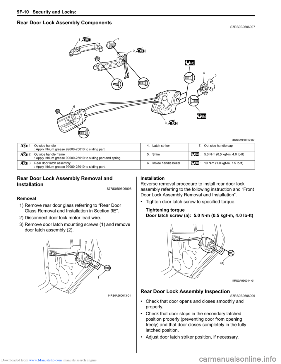
Rear Door Lock Assembly ComponentsS7RS0B9606007
Rear Door Lock Assembly Removal and
Installation
S7RS0B9606008
Removal1) Remove rear door glass referring to “Rear Door Glass Removal and Installation in Section 9E”.
2) Disconnect door lock motor lead wire.
3) Remove door latch mounting screws (1) and remove door latch assembly (2). Installation
Reverse removal procedure to install rear door lock
assembly referring to the following instruction and “Front
Door Lock Assembly Re
moval and Installation”.
• Tighten door latch screw to specified torque.
Tightening torque
Door latch screw (a): 5.0 N·m (0.5 kgf-m, 4.0 lb-ft)
Rear Door Lock Assembly InspectionS7RS0B9606009
• Check that door opens and closes smoothly and properly.
• Check that door stops in the secondary latched position properly (preventing door from opening
freely) and that door closes completely in the fully
latched position.
• Adjust door latch strike r position, if necessary.
(a)
(b)
1
7
2
6
3 4
5
I4RS0A960012-02
1. Outside handle
: Apply lithium grease 99000-25010 to sliding part. 4. Latch striker 7. Out side handle cap
2. Outside handle frame : Apply lithium grease 99000-25010 to sliding part and spring. 5. Shim : 5.0 N
⋅m (0.5 kgf-m, 4.0 lb-ft)
3. Rear door latch assembly : Apply lithium grease 99000-25010 to sliding part. 6. Inside handle bezel : 10 N
⋅m (1.0 kgf-m, 7.5 lb-ft)
1
2
I4RS0A960013-01
(a)
I4RS0A960014-01
Page 1492 of 1496
Downloaded from www.Manualslib.com manuals search engine 10E-30 Keyless Start System:
Repair Instructions
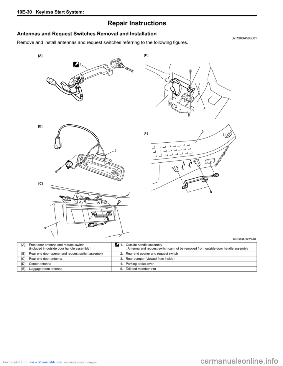
Antennas and Request Switches Removal and InstallationS7RS0BA506001
Remove and install antennas and request switches referring to the following figures.
[A]
[B][D]
[C] [E]
1
2
3
4
5
I4RS0BA50027-04
[A]: Front door antenna and request switch
(included in outside door handle assembly) 1. Outside handle assembly
: Antenna and request switch can not be removed from outside door handle assembly
[B]: Rear end door opener and request switch assembly 2. Rear end opener and request switch
[C]: Rear end door antenna 3. Rear bumper (viewed from inside)
[D]: Center antenna 4. Parking brake lever [E]: Luggage room antenna 5. Tail end member trim