2008 SUZUKI SWIFT operation procedure for refrigerant charge
[x] Cancel search: operation procedure for refrigerant chargePage 515 of 1496
Downloaded from www.Manualslib.com manuals search engine Brake Control System and Diagnosis: 4A-17
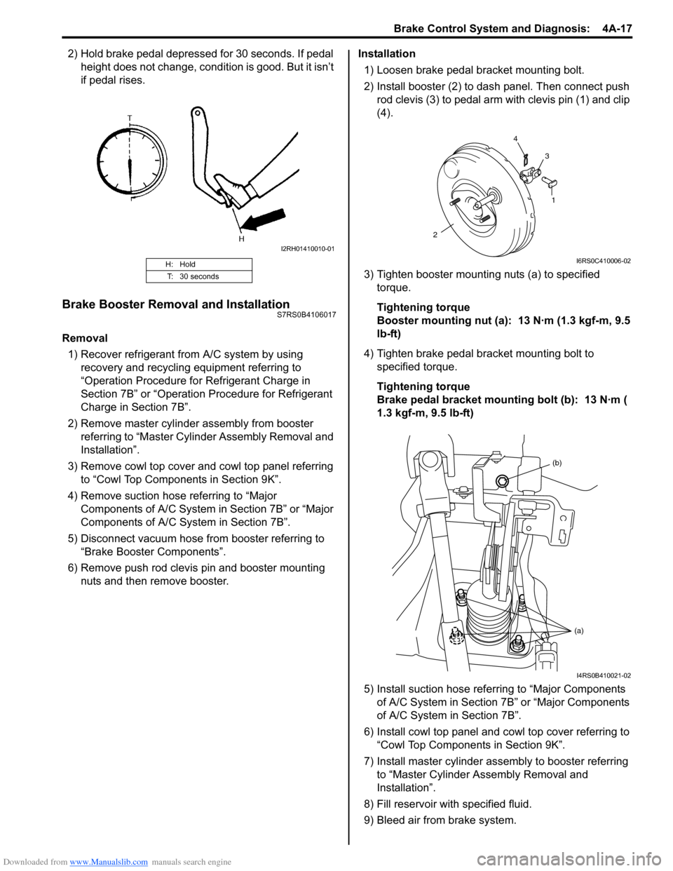
2) Hold brake pedal depressed for 30 seconds. If pedal height does not change, condition is good. But it isn’t
if pedal rises.
Brake Booster Removal and InstallationS7RS0B4106017
Removal
1) Recover refrigerant from A/C system by using recovery and recycling equipment referring to
“Operation Procedure for Refrigerant Charge in
Section 7B” or “Operation Procedure for Refrigerant
Charge in Section 7B”.
2) Remove master cylinder assembly from booster referring to “Master Cylin der Assembly Removal and
Installation”.
3) Remove cowl top cover and cowl top panel referring to “Cowl Top Components in Section 9K”.
4) Remove suction hose referring to “Major Components of A/C System in Section 7B” or “Major
Components of A/C System in Section 7B”.
5) Disconnect vacuum hose from booster referring to “Brake Booster Components”.
6) Remove push rod clevis pin and booster mounting nuts and then remove booster. Installation
1) Loosen brake pedal bracket mounting bolt.
2) Install booster (2) to dash panel. Then connect push rod clevis (3) to pedal arm with clevis pin (1) and clip
(4).
3) Tighten booster mounting nuts (a) to specified torque.
Tightening torque
Booster mounting nut (a): 13 N·m (1.3 kgf-m, 9.5
lb-ft)
4) Tighten brake pedal bracket mounting bolt to specified torque.
Tightening torque
Brake pedal bracket mounting bolt (b): 13 N·m (
1.3 kgf-m, 9.5 lb-ft)
5) Install suction hose referring to “Major Components of A/C System in Section 7B” or “Major Components
of A/C System in Section 7B”.
6) Install cowl top panel and cowl top cover referring to
“Cowl Top Components in Section 9K”.
7) Install master cylinder assembly to booster referring to “Master Cylinder Assembly Removal and
Installation”.
8) Fill reservoir with specified fluid.
9) Bleed air from brake system.
H: Hold
T: 30 seconds
I2RH01410010-01
1
2 4
3
I6RS0C410006-02
(b)
(a)
I4RS0B410021-02
Page 516 of 1496
Downloaded from www.Manualslib.com manuals search engine 4A-18 Brake Control System and Diagnosis:
10) Check pedal height and play referring to “Brake Pedal Free Height Inspection” and “Brake Pedal
Play Inspection”.
11) Check each installed part for fluid leakage and perform brake test.
12) Evacuate and charge refrigerant by referring to “Evacuating of A/C Syst em” and “Procedure of
Charging” under “Operation Procedure for
Refrigerant Charge in Section 7B” or “Operation
Procedure for Refrigerant Charge in Section 7B”.
Brake Booster Inspection and AdjustmentS7RS0B4106018
Installation Position of Push Rod
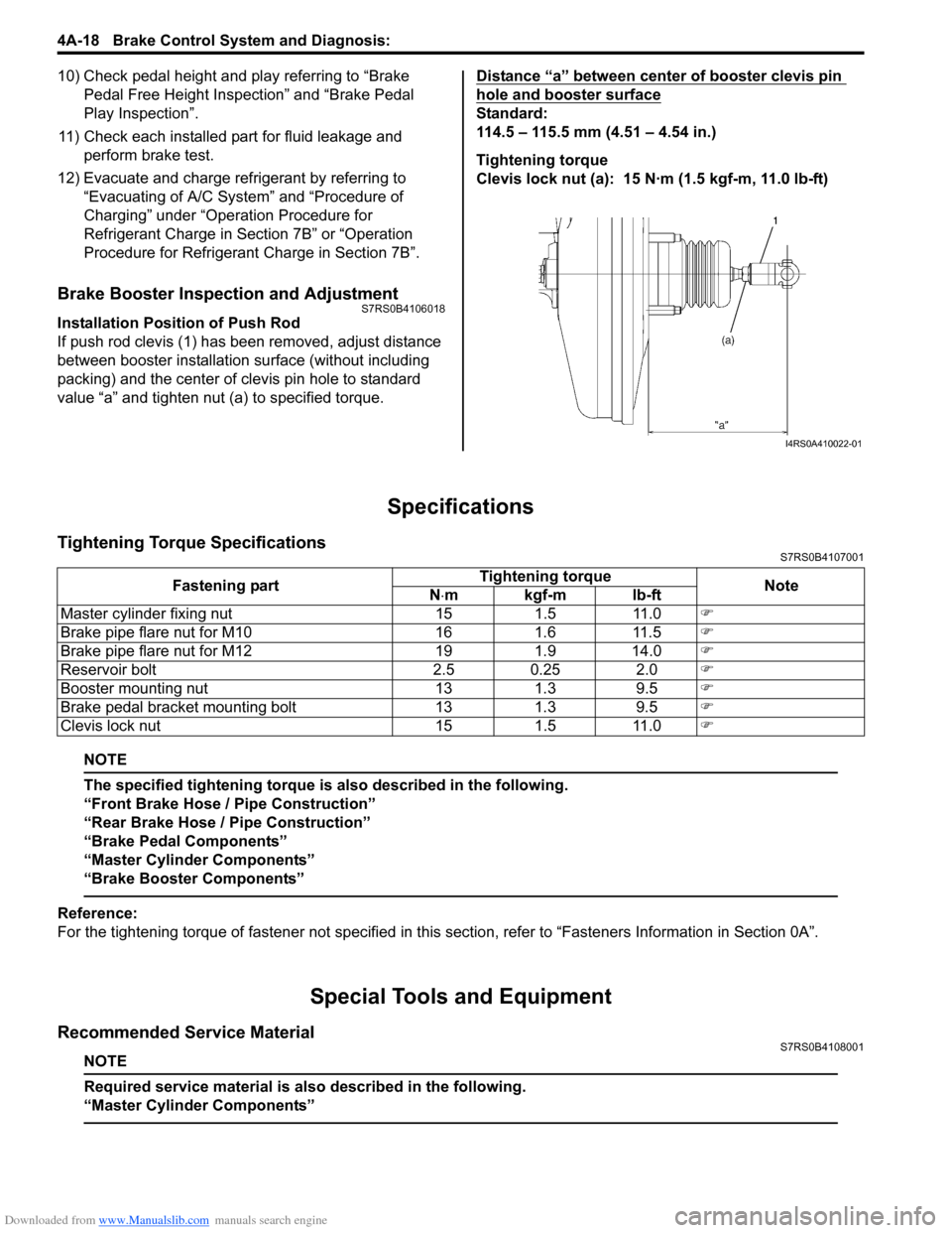
If push rod clevis (1) has b een removed, adjust distance
between booster installation surface (without including
packing) and the center of clevis pin hole to standard
value “a” and tighten nut (a) to specified torque. Distance “a” between center of booster clevis pin
hole and booster surface
Standard:
114.5 – 115.5 mm (4.51 – 4.54 in.)
Tightening torque
Clevis lock nut (a): 15 N·m (1.5 kgf-m, 11.0 lb-ft)
Specifications
Tightening Torque SpecificationsS7RS0B4107001
NOTE
The specified tightening torque is also described in the following.
“Front Brake Hose / Pipe Construction”
“Rear Brake Hose / Pipe Construction”
“Brake Pedal Components”
“Master Cylinder Components”
“Brake Booster Components”
Reference:
For the tightening torque of fastener not specified in this
section, refer to “Fasteners Information in Section 0A”.
Special Tools and Equipment
Recommended Service MaterialS7RS0B4108001
NOTE
Required service material is also described in the following.
“Master Cylinder Components”
I4RS0A410022-01
Fastening part Tightening torque
Note
N ⋅mkgf-mlb-ft
Master cylinder fixing nut 15 1.5 11.0 )
Brake pipe flare nut for M10 16 1.6 11.5 )
Brake pipe flare nut for M12 19 1.9 14.0 )
Reservoir bolt 2.5 0.25 2.0 )
Booster mounting nut 13 1.3 9.5 )
Brake pedal bracket mounting bolt 13 1.3 9.5 )
Clevis lock nut 15 1.5 11.0 )
Page 933 of 1496
Downloaded from www.Manualslib.com manuals search engine Table of Contents 7- i
7
Section 7
CONTENTS
HVAC
Precautions ................................................. 7-1
Precautions............................................................. 7-1
Precautions on HVAC ........................................... 7-1
Heater and Ventilation.... ......................... 7A-1
General Description ............................................. 7A-1
Heater and Ventilation Construction ................... 7A-1
Schematic and Routing Diagram ........................ 7A-2 Heater and Ventilation Wiring Circuit Diagram .... 7A-2
Diagnostic Information and Procedures ............ 7A-3 Heater and Ventilation Symptom Diagnosis........ 7A-3
Repair Instructions .............................................. 7A-4 HVAC Unit Components ..................................... 7A-4
HVAC Unit Removal and Installation .................. 7A-4
Blower Motor Removal and Installation............... 7A-4
Blower Motor Inspection ..................................... 7A-4
Blower Motor Resistor Removal and Installation ......................................................... 7A-5
Blower Motor Resistor Inspection ....................... 7A-5
Blower Motor Relay Inspection ........................... 7A-6
HVAC Control Unit Components ......................... 7A-6
HVAC Control Unit Remova l and Installation ...... 7A-7
Blower Speed Selector In spection ...................... 7A-9
Air Intake Selector Inspec tion ............................. 7A-9
Air Intake Control Actuator Removal and Installation ......................................................... 7A-9
Air Intake Control Actuator Inspection .............. 7A-10
Center Ventilation Louver Removal and Installation ....................................................... 7A-10
Side Ventilation Louver Removal and Installation ....................................................... 7A-11
HVAC Air Filter Removal and Installation (If Equipped)........................................................ 7A-12
HVAC Air Filter Inspection (If Equipped) ........... 7A-12
Air Conditioning System... ...................... 7B-1
Manual Type ............................................................ 7B-1
Precautions........................................................... 7B-1A/C System Caution ............................................ 7B-1
Precautions on Servicing A/C System ................ 7B-1
General Description ............................................. 7B-3 Refrigerant Type Identifica tion ............................ 7B-3
Sub-Cool A/C System Description ...................... 7B-4
A/C Operation Description .................................. 7B-4 Schematic and Routing Diagram ........................7B-5
Major Components of A/C System ...................... 7B-5
A/C System Wiring Diagram ............................... 7B-6
Diagnostic Information and Procedures ............7B-7 A/C System Symptom Diagnosis ........................ 7B-7
Abnormal Noise Sympto m Diagnosis of A/C
System .............................................................. 7B-9
A/C System Performance Inspection ................ 7B-10
A/C System Inspection at ECM ......................... 7B-15
Repair Instructions ........... .................................7B-16
Operation Procedure for Re frigerant Charge .... 7B-16
Condenser Assembly On-Vehicle Inspection .... 7B-21
Condenser Assembly Removal and Installation ....................................................... 7B-21
Receiver/Dryer Removal and Installation .......... 7B-22
HVAC Unit Components ................................... 7B-23
HVAC Unit Removal and In stallation ................ 7B-24
Evaporator Inspection ....................................... 7B-24
Evaporator Thermistor (Evaporator Temperature Sensor) Removal and
Installation ....................................................... 7B-25
Evaporator Thermistor (Evaporator Temperature Sensor) Inspec tion..................... 7B-25
Expansion Valve Removal and Installation ....... 7B-26
Expansion Valve Inspection .............................. 7B-26
A/C Refrigerant Pressure Sensor and Its Circuit Inspection............................................. 7B-26
A/C Refrigerant Pressu re Sensor Removal
and Installation ................................................ 7B-26
A/C Switch Inspection ....................................... 7B-27
Compressor Relay Inspection ........................... 7B-27
Compressor Drive Belt Inspection and Adjustment ...................................................... 7B-27
Compressor Drive Belt Removal and Installation ....................................................... 7B-28
Compressor Assembly Removal and Installation ....................................................... 7B-28
Compressor Assembly Components................. 7B-29
Magnet Clutch Inspection.................................. 7B-29
Magnet Clutch Removal and Installation........... 7B-29
Relief Valve Inspection...................................... 7B-31
Relief Valve Removal and Installation............... 7B-32
Specifications .................... .................................7B-32
Tightening Torque Specifications ...................... 7B-32
Special Tools and Equipmen t ...........................7B-33
Page 934 of 1496
Downloaded from www.Manualslib.com manuals search engine 7-ii Table of Contents
Recommended Service Material ....................... 7B-33
Special Tool ...................................................... 7B-33
Automatic Type .................... .................................7B-34
Precautions.........................................................7B-34 A/C System Caution .......................................... 7B-34
Precautions in Diagnosing Trouble ................... 7B-34
Precautions on Servicing A/C System .............. 7B-34
General Description .......... .................................7B-34
Auto A/C System Descript ion ............................ 7B-34
HVAC Control Module Operation Description ... 7B-36
Refrigerant Type Identifica tion .......................... 7B-36
Sub-Cool A/C System Description .................... 7B-36
A/C Operation Description ................................ 7B-36
On-Board Diagnostic System Description ......... 7B-37
Schematic and Routing Diagram ......................7B-37 Major Components of A/C System .................... 7B-37
A/C System Wiring Diagra m ............................. 7B-38
Diagnostic Information and Procedures ..........7B-39 A/C System Symptom Diagnosis ...................... 7B-39
Abnormal Noise Sympto m Diagnosis of A/C
System ............................................................ 7B-42
DTC Check........................................................ 7B-42
DTC Clearance ................................................. 7B-43
DTC Table ......................................................... 7B-44
Fail-Safe Table ................. ................................. 7B-45
Scan Tool Data ................................................. 7B-46
Air Conditioning System Check......................... 7B-47
Visual Inspection ............................................... 7B-49
DTC B1502: Inside Air Temperature Sensor and/or Its Circuit Malfunction .......................... 7B-49
DTC B1503: A/C Evaporator Air Temperature Sensor and/or Its Circuit Malfunction .............. 7B-50
DTC B1504: Sunload Sensor and/or Its Circuit Malfunction ......... ................................. 7B-52
DTC B1511: Temperature Control Actuator (Position Sensor) and/or Its Circuit
Malfunction ...................................................... 7B-53
DTC B1512: Air flow Control Actuator (Position Sensor) and/or Its Circuit
Malfunction ...................................................... 7B-55
DTC B1513: Temperature Control Actuator and/or Its Circuit Malfunction .......................... 7B-57
DTC B1514: Air Flow Co ntrol Actuator and/or
Its Circuit Malfunction ...................................... 7B-60
DTC B1541: HVAC Control Module Back-Up Power Supply Malfunction .............................. 7B-62
DTC B1546: A/C Refrigerant Pressure Malfunction ...................................................... 7B-63
DTC B1551: Serial Communication Circuit Malfunction ...................................................... 7B-63
DTC B1552: Serial Communication Signal Malfunction ...................................................... 7B-64
DTC B1553: CAN Communication Signal Malfunction ...................................................... 7B-65
DTC B1557: Vehicle Speed Sensor Signal Malfunction ...................................................... 7B-65
DTC B1561: Engine Coolant Temperature Sensor Signal Malfunctio n .............................. 7B-66 DTC B1562: Outside Air Temperature Sensor
Signal Malfunction ........................................... 7B-66
DTC B1563: A/C Refr igerant Pressure
Sensor Signal Malfunction .............................. 7B-66
Inspection of HVAC Control Module and Its Circuit .............................................................. 7B-67
A/C System Performance Inspection ................ 7B-70
A/C System Inspection at ECM ......................... 7B-70
Repair Instructions ............ ................................7B-71
Operation Procedure for Refrigerant Charge .... 7B-71
HVAC Unit Components ................................... 7B-72
HVAC Unit Removal and In stallation ................ 7B-73
Temperature Control Actuator Removal and Installation ....................................................... 7B-73
Temperature Control Actuat or Inspection ......... 7B-73
Air Flow Control Actuator Removal and Installation ....................................................... 7B-74
Air Flow Control Actuator Inspection ................. 7B-74
Air Intake Control Actuator Removal and Installation ....................................................... 7B-75
Air Intake Control Actuator Inspection............... 7B-75
Actuator Linkage Inspection .............................. 7B-76
Blower Motor Controller Removal and Installation ....................................................... 7B-76
Blower Motor Controller Inspection ................... 7B-76
HVAC Control Module Removal and Installation ....................................................... 7B-77
Sunload Sensor Removal and Installation ........ 7B-77
Sunload Sensor Inspection ............................... 7B-77
Outside Air Temperature Sensor Removal and Installation ................................................ 7B-77
Outside Air Temperature Sensor Inspection ..... 7B-77
Inside Air Temperature Sensor Removal and Installation ....................................................... 7B-78
Inside Air Temperature Sens or Inspection ........ 7B-78
Condenser Assembly On-Vehicle Inspection .... 7B-78
Condenser Assembly Removal and Installation ....................................................... 7B-78
Receiver/Dryer Removal and Installation .......... 7B-78
Evaporator Inspection ....................................... 7B-78
Evaporator Temperature Sensor Removal and Installation ................................................ 7B-78
Evaporator Temperature Se nsor Inspection ..... 7B-78
Expansion Valve Removal an d Installation ....... 7B-78
Expansion Valve Inspection .............................. 7B-78
A/C Refrigerant Pressure Sensor and Its Circuit Inspection............................................. 7B-78
A/C Refrigerant Pressu re Sensor Removal
and Installation ................................................ 7B-78
Compressor Relay Inspection .
.......................... 7B-78
Compressor Drive Belt Inspection and Adjustment ...................................................... 7B-78
Compressor Drive Belt Removal and Installation ....................................................... 7B-79
Compressor Assembly Removal and Installation ....................................................... 7B-79
Compressor Assembly Components................. 7B-79
Magnet Clutch Removal and Installation........... 7B-79
Magnet Clutch Inspection.................................. 7B-79
Relief Valve Inspection...................................... 7B-79
Page 950 of 1496
Downloaded from www.Manualslib.com manuals search engine 7B-2 Air Conditioning System: Manual Type
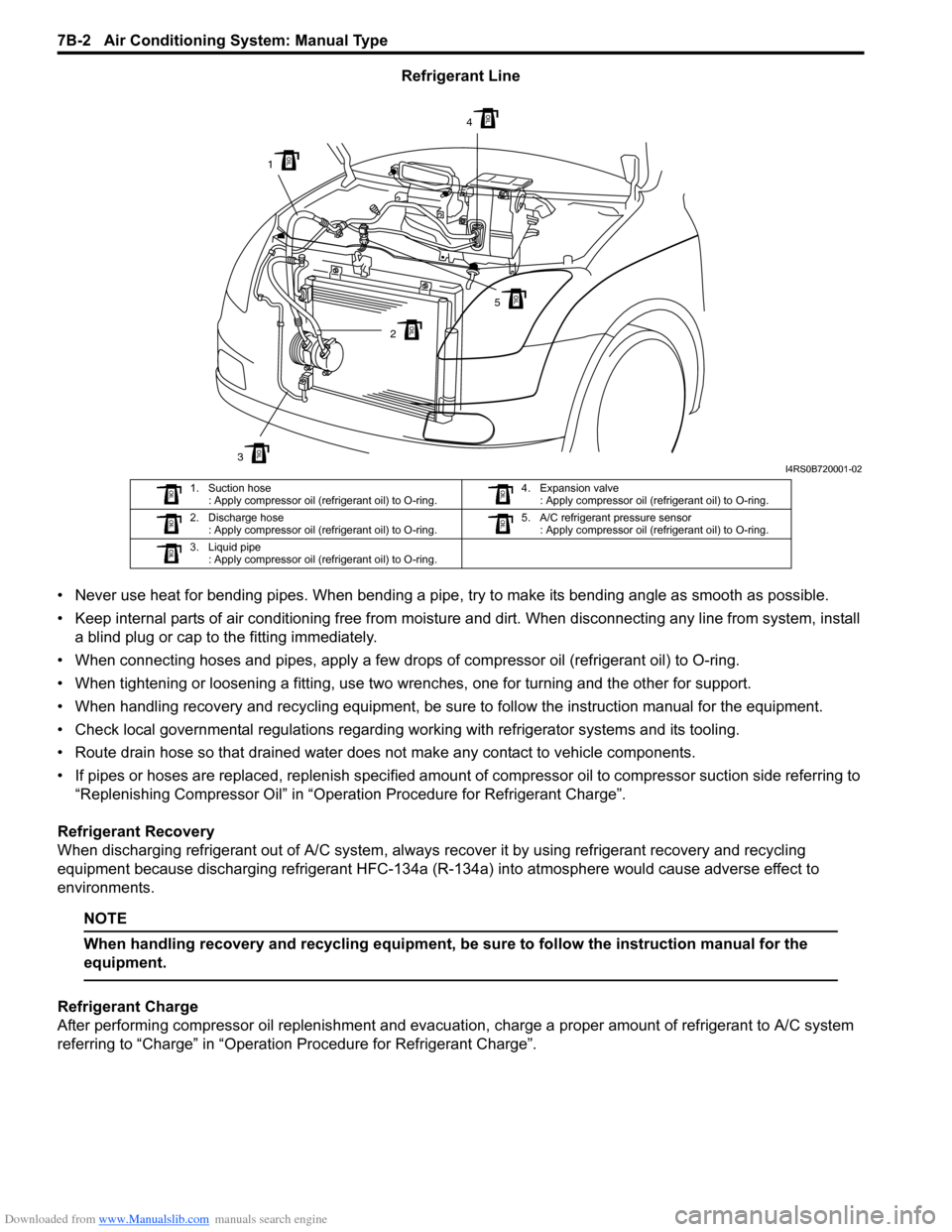
Refrigerant Line
• Never use heat for bending pipes. When bending a pipe , try to make its bending angle as smooth as possible.
• Keep internal parts of air conditioning free from moistu re and dirt. When disconnecting any line from system, install
a blind plug or cap to the fitting immediately.
• When connecting hoses and pipes, apply a few drops of compressor oil (refrigerant oil) to O-ring.
• When tightening or loosening a fitting, use two wrenches, one for turning and the other for support.
• When handling recovery and recycling equipment, be sure to follow the instruction manual for the equipment.
• Check local governmental regulations regarding working with refrigerator systems and its tooling.
• Route drain hose so that drained water does not make any contact to vehicle components.
• If pipes or hoses are replaced, replenish specified amount of compressor oil to compre ssor suction side referring to
“Replenishing Compressor Oil” in “Operation Procedure for Refrigerant Charge”.
Refrigerant Recovery
When discharging refrigerant out of A/C system, always recover it by using refrigerant recovery and recycling
equipment because discharging refrigerant HFC-134a (R-1 34a) into atmosphere would cause adverse effect to
environments.
NOTE
When handling recovery and recycling equipment, be sure to follow the instruction manual for the
equipment.
Refrigerant Charge
After performing compressor oil replenishment and evacuat ion, charge a proper amount of refrigerant to A/C system
referring to “Charge” in “Operation Procedure for Refrigerant Charge”.
3
1
2
4
5
I4RS0B720001-02
1. Suction hose : Apply compressor oil (refrigerant oil) to O-ring. 4. Expansion valve
: Apply compressor oil (refrigerant oil) to O-ring.
2. Discharge hose : Apply compressor oil (refrigerant oil) to O-ring. 5. A/C refrigerant pressure sensor
: Apply compressor oil (refrigerant oil) to O-ring.
3. Liquid pipe : Apply compressor oil (refrigerant oil) to O-ring.
Page 955 of 1496
Downloaded from www.Manualslib.com manuals search engine Air Conditioning System: Manual Type 7B-7
Diagnostic Information and Procedures
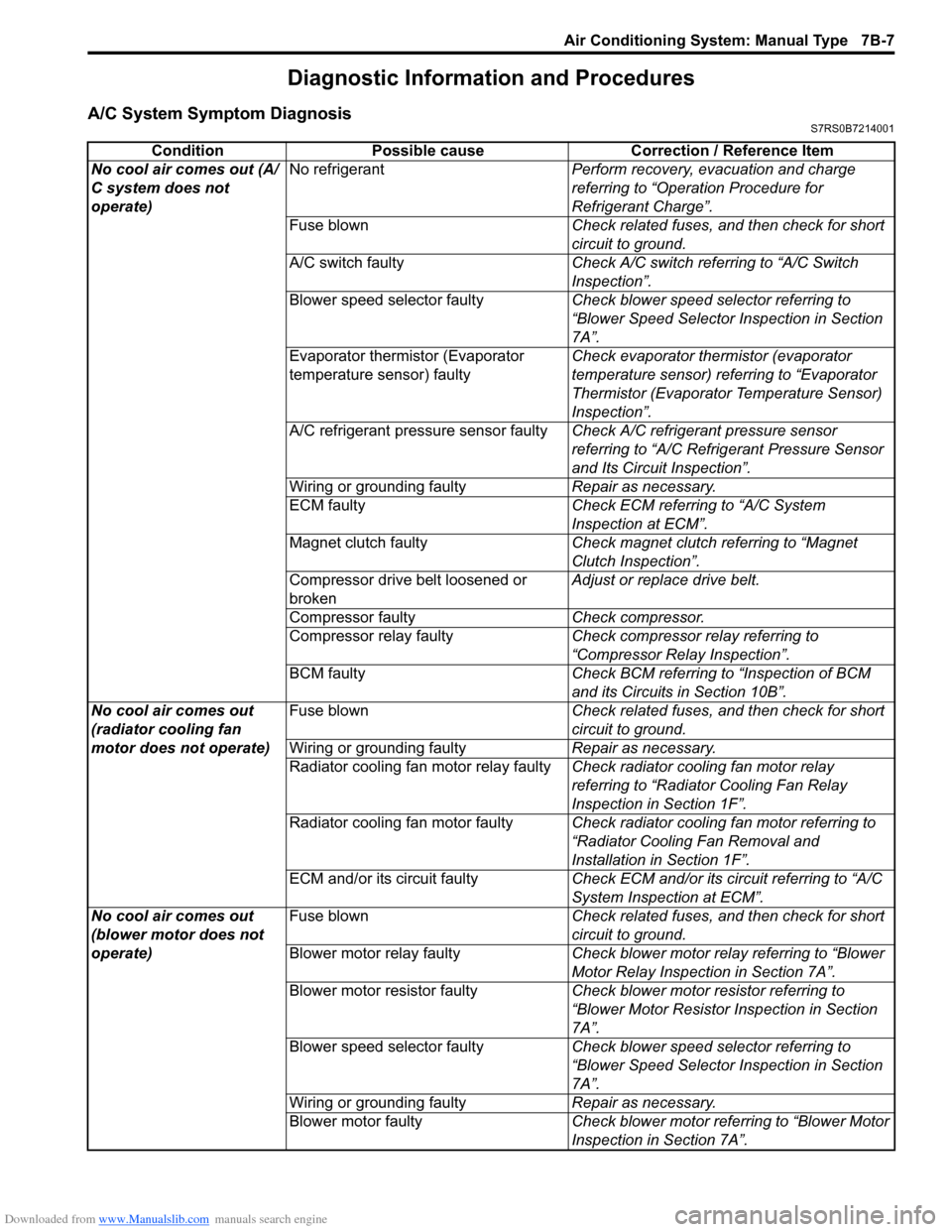
A/C System Symptom DiagnosisS7RS0B7214001
ConditionPossible cause Correction / Reference Item
No cool air comes out (A/
C system does not
operate) No refrigerant
Perform recovery, evacuation and charge
referring to “Operation Procedure for
Refrigerant Charge”.
Fuse blown Check related fuses, and then check for short
circuit to ground.
A/C switch faulty Check A/C switch referring to “A/C Switch
Inspection”.
Blower speed selector faulty Check blower speed selector referring to
“Blower Speed Selector Inspection in Section
7A”.
Evaporator thermistor (Evaporator
temperature sensor) faulty Check evaporator thermistor (evaporator
temperature sensor) referring to “Evaporator
Thermistor (Evaporator Temperature Sensor)
Inspection”.
A/C refrigerant pressure sensor faulty Check A/C refrigerant pressure sensor
referring to “A/C Refrigerant Pressure Sensor
and Its Circuit Inspection”.
Wiring or grounding faulty Repair as necessary.
ECM faulty Check ECM referring to “A/C System
Inspection at ECM”.
Magnet clutch faulty Check magnet clutch referring to “Magnet
Clutch Inspection”.
Compressor drive belt loosened or
broken Adjust or replace drive belt.
Compressor faulty Check compressor.
Compressor relay faulty Check compressor relay referring to
“Compressor Relay Inspection”.
BCM faulty Check BCM referring to “Inspection of BCM
and its Circuits in Section 10B”.
No cool air comes out
(radiator cooling fan
motor does not operate) Fuse blown
Check related fuses, and then check for short
circuit to ground.
Wiring or grounding faulty Repair as necessary.
Radiator cooling fan motor relay faulty Check radiator cooling fan motor relay
referring to “Radiator Cooling Fan Relay
Inspection in Section 1F”.
Radiator cooling fan motor faulty Check radiator cooling fan motor referring to
“Radiator Cooling Fan Removal and
Installation in Section 1F”.
ECM and/or its circuit faulty Check ECM and/or its circuit referring to “A/C
System Inspection at ECM”.
No cool air comes out
(blower motor does not
operate) Fuse blown
Check related fuses, and then check for short
circuit to ground.
Blower motor relay faulty Check blower motor relay referring to “Blower
Motor Relay Inspection in Section 7A”.
Blower motor resistor faulty Check blower motor resistor referring to
“Blower Motor Resistor Inspection in Section
7A”.
Blower speed selector faulty Check blower speed selector referring to
“Blower Speed Selector Inspection in Section
7A”.
Wiring or grounding faulty Repair as necessary.
Blower motor faulty Check blower motor referring to “Blower Motor
Inspection in Section 7A”.
Page 956 of 1496
Downloaded from www.Manualslib.com manuals search engine 7B-8 Air Conditioning System: Manual Type
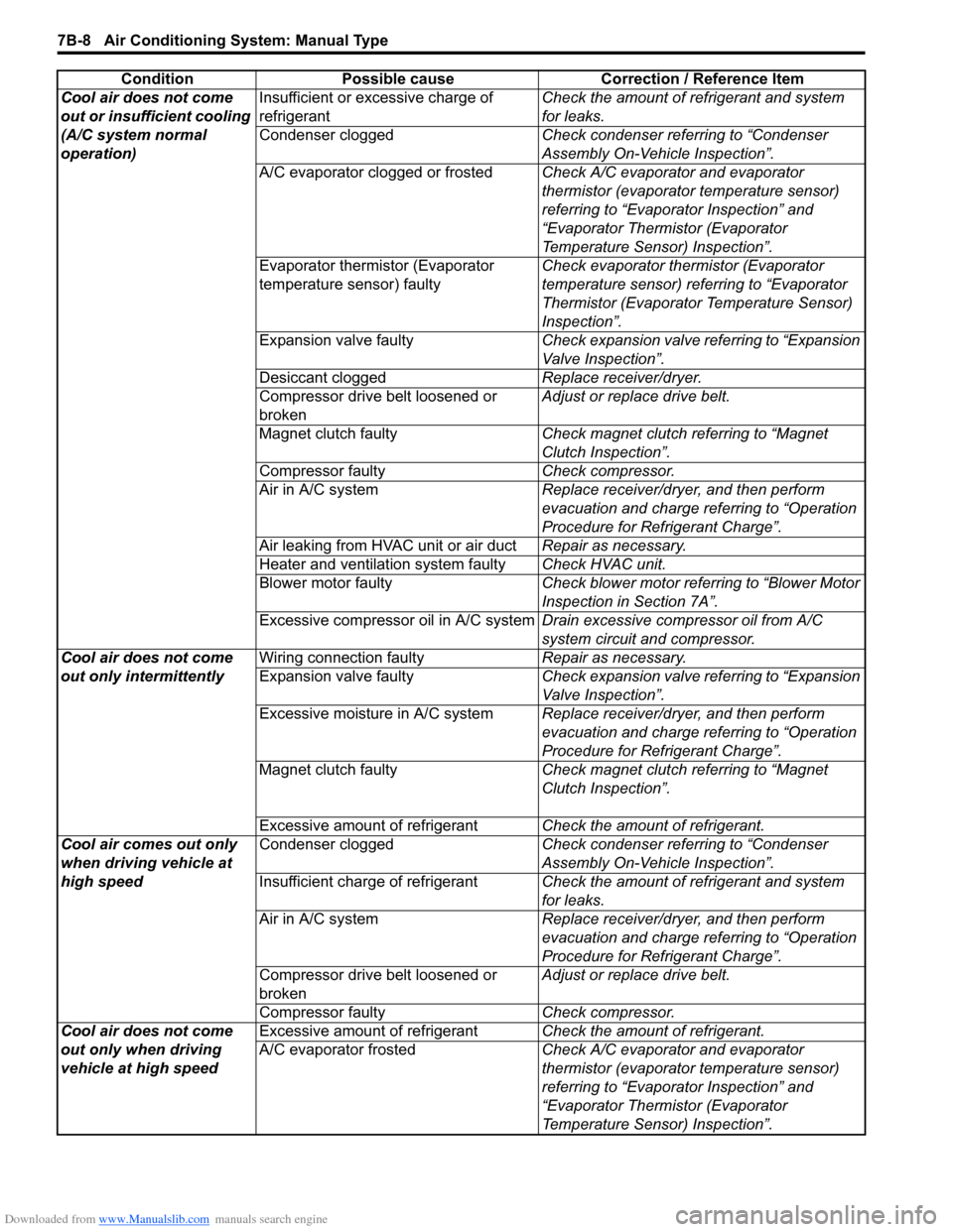
Cool air does not come
out or insufficient cooling
(A/C system normal
operation)Insufficient or excessive charge of
refrigerant
Check the amount of refrigerant and system
for leaks.
Condenser clogged Check condenser referring to “Condenser
Assembly On-Vehicle Inspection”.
A/C evaporator clogged or frosted Check A/C evaporator and evaporator
thermistor (evaporator temperature sensor)
referring to “Evaporator Inspection” and
“Evaporator Thermistor (Evaporator
Temperature Sensor) Inspection”.
Evaporator thermistor (Evaporator
temperature sensor) faulty Check evaporator thermistor (Evaporator
temperature sensor) referring to “Evaporator
Thermistor (Evaporator Temperature Sensor)
Inspection”.
Expansion valve faulty Check expansion valve referring to “Expansion
Valve Inspection”.
Desiccant clogged Replace receiver/dryer.
Compressor drive belt loosened or
broken Adjust or replace drive belt.
Magnet clutch faulty Check magnet clutch referring to “Magnet
Clutch Inspection”.
Compressor faulty Check compressor.
Air in A/C system Replace receiver/dryer, and then perform
evacuation and charge referring to “Operation
Procedure for Refrigerant Charge”.
Air leaking from HVAC unit or air duct Repair as necessary.
Heater and ventilation system faulty Check HVAC unit.
Blower motor faulty Check blower motor referring to “Blower Motor
Inspection in Section 7A”.
Excessive compressor oil in A/C system Drain excessive compressor oil from A/C
system circuit and compressor.
Cool air does not come
out only intermittently Wiring connection faulty
Repair as necessary.
Expansion valve faulty Check expansion valve referring to “Expansion
Valve Inspection”.
Excessive moisture in A/C system Replace receiver/dryer, and then perform
evacuation and charge referring to “Operation
Procedure for Refrigerant Charge”.
Magnet clutch faulty Check magnet clutch referring to “Magnet
Clutch Inspection”.
Excessive amount of refrigerant Check the amount of refrigerant.
Cool air comes out only
when driving vehicle at
high speed Condenser clogged
Check condenser referring to “Condenser
Assembly On-Vehicle Inspection”.
Insufficient charge of refrigerant Check the amount of refrigerant and system
for leaks.
Air in A/C system Replace receiver/dryer, and then perform
evacuation and charge referring to “Operation
Procedure for Refrigerant Charge”.
Compressor drive belt loosened or
broken Adjust or replace drive belt.
Compressor faulty Check compressor.
Cool air does not come
out only when driving
vehicle at high speed Excessive amount of refrigerant
Check the amount of refrigerant.
A/C evaporator frosted Check A/C evaporator and evaporator
thermistor (evaporator temperature sensor)
referring to “Evaporator Inspection” and
“Evaporator Thermistor (Evaporator
Temperature Sensor) Inspection”.
Condition Possible cause Correction / Reference Item
Page 964 of 1496
Downloaded from www.Manualslib.com manuals search engine 7B-16 Air Conditioning System: Manual Type
Repair Instructions
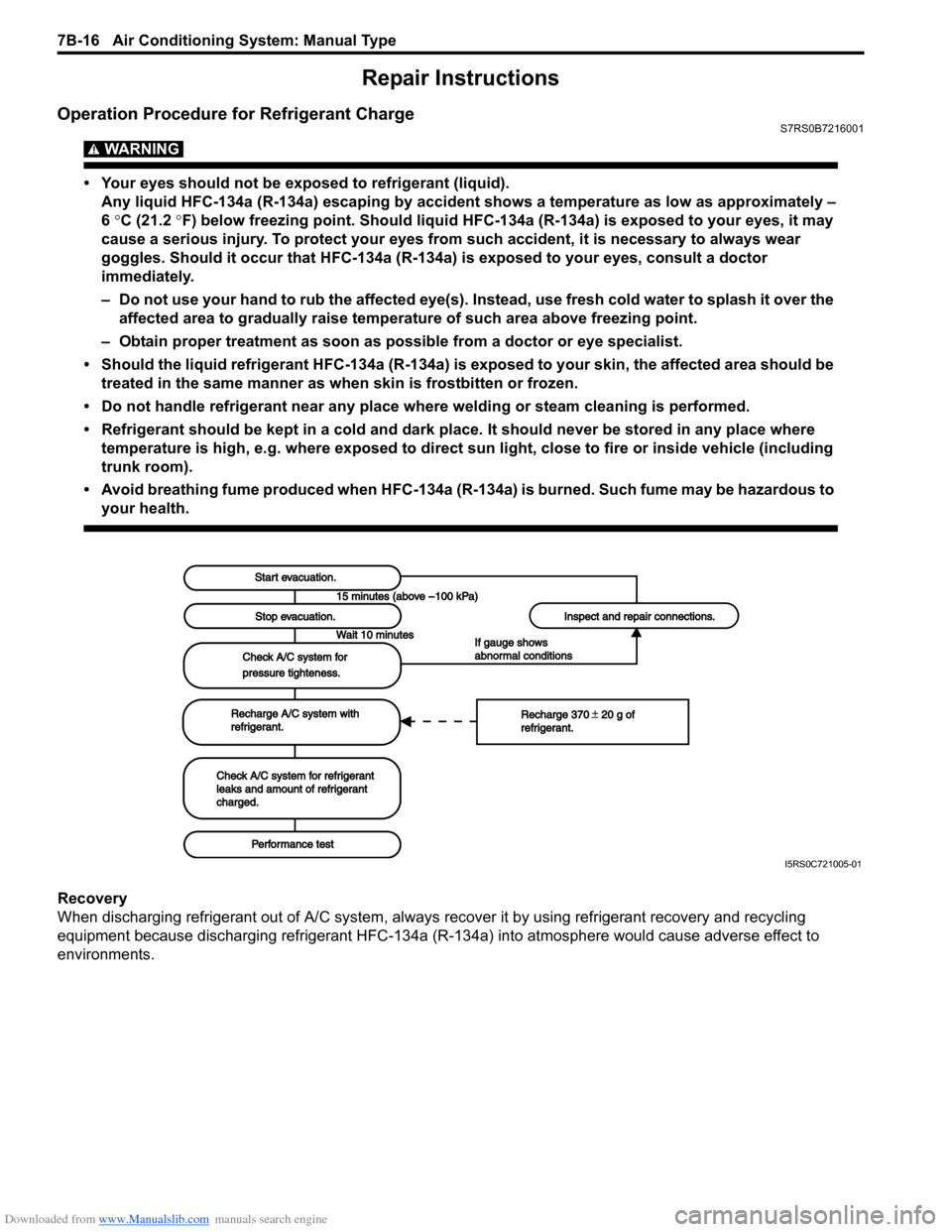
Operation Procedure for Refrigerant ChargeS7RS0B7216001
WARNING!
• Your eyes should not be exposed to refrigerant (liquid).Any liquid HFC-134a (R-134a) escaping by accident shows a temperature as low as approximately –
6 °C (21.2 ° F) below freezing point. Should liquid HFC-134a (R-134a) is exposed to your eyes, it may
cause a serious injury. To protect your eyes from such accident, it is necessary to always wear
goggles. Should it occur that HFC-134a (R-134a) is exposed to your eyes, consult a doctor
immediately.
– Do not use your hand to rub the affected eye(s). Instead, use fresh cold water to splash it over the affected area to gradually raise temperature of such area above freezing point.
– Obtain proper treatment as soon as possible from a doctor or eye specialist.
• Should the liquid refrigerant HFC-134a (R-134a) is exposed to your skin, the affected area should be treated in the same manner as when skin is frostbitten or frozen.
• Do not handle refrigerant near any place where welding or steam cleaning is performed.
• Refrigerant should be kept in a cold and dark pl ace. It should never be stored in any place where
temperature is high, e.g. where exposed to direct su n light, close to fire or inside vehicle (including
trunk room).
• Avoid breathing fume produced when HFC-134a (R-134a) is burned. Such fume may be hazardous to your health.
Recovery
When discharging refrigerant out of A/C system, always recover it by using refrigerant recovery and recycling
equipment because discharging refrigerant HFC-134a (R-1 34a) into atmosphere would cause adverse effect to
environments.
Start evacuation.Start evacuation.
Stop evacuation.Stop evacuation.
Wait 10 minutesWait 10 minutes
Check A/C system forCheck A/C system for
pressure tighteness.pressure tighteness.
Recharge A/C system withRecharge A/C system withrefrigerant.refrigerant.
Check A/C system for refrigerantCheck A/C system for refrigerantleaks and amount of refrigerantleaks and amount of refrigerantcharged.charged.
Performance testPerformance test
Inspect and repair connections.Inspect and repair connections.
If gauge showsIf gauge showsabnormal conditionsabnormal conditions
Recharge 370 20 g ofRecharge 370 20 g ofrefrigerant.refrigerant.
I5RS0C721005-01