2008 SUZUKI SWIFT Wiring light
[x] Cancel search: Wiring lightPage 2 of 1496
Downloaded from www.Manualslib.com manuals search engine IMPORTANT
WARNING/CAUTION/NOTE
Please read this manual and follow its instructions carefully. To emphasize special information, the words , and NOTE have special meanings. Pay specia l attention to the messages high-
lighted by these signal words.
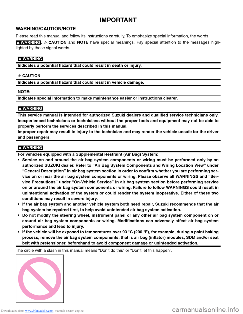
The circle with a slash in this manual me ans “Don’t do this” or “Don’t let this happen”.
WARNING!CAUTION!
Indicates a potential hazard that could result in death or injury.
WARNING!
Indicates a potential hazard that could result in vehicle damage.
CAUTION!
NOTE:
Indicates special information to make main tenance easier or instructions clearer.
This service manual is intended for authorized Su zuki dealers and qualified service technicians only.
Inexperienced technicians or technicians without the proper tools and equipment may not be able to
properly perform the services described in this manual.
Improper repair may result in injury to the technician and may render the vehicle unsafe for the driver
and passengers.
WARNING!
For vehicles equipped with a Supplemental Restraint (Air Bag) System:
• Service on and around the air bag system components or wiring must be performed only by an authorized SUZUKI dealer. Refer to “Air Bag System Components and Wiring Location View” under
“General Description” in air bag system section in order to confirm whether you are performing ser-
vice on or near the air bag system components or wiring. Please observe all WARNINGS and “Ser-
vice Precautions” under “On-Vehicl e Service” in air bag system section before performing service
on or around the air bag system components or wiring. Failure to follow WARNINGS could result in
unintentional activation of the system or could re nder the system inoperative. Either of these two
conditions may result in severe injury.
If the air bag system and another vehicle system both need repair, Suzuki recommends that the air
bag system be repaired first, to help av oid unintended air bag system activation.
Do not modify the steering wheel, instrument pa nel or any other air bag system component on or
around air bag system components or wiring. Modi fications can adversely affect air bag system
performance and lead to injury.
If the vehicle will be exposed to temperatures over 93 °C (200 °F), for example, during a paint baking
process, remove the air bag system components, th at is air bag (inflator) modules, SDM and/or seat
belt with pretensioner, beforehand to avoid component damage or unintended activation.
WARNING!
Page 4 of 1496

Downloaded from www.Manualslib.com manuals search engine 00
0
1
2
3
4
5
6
7
8
9
10
11
Vo l u m e 1
Precautions............................................................... 00-iPrecautions ............................................................ 00-1
General Information ................ ................................... 0-i
General Information ............................................... 0A-1
Maintenance and Lubricatio n ................................. 0B-1
Engine ......................................................................... 1-i Precautions .............................................................. 1-1
Engine General Information and Diagnosis ........... 1A-1
Aux. Emission Control Devices .............................. 1B-1
Engine Electrical Devices....................................... 1C-1
Engine Mechanical ................................................. 1D-1
Engine Lubrication System .................................... 1E-1
Engine Cooling System .......................................... 1F-1
Fuel System ...........................................................1G-1
Ignition System....................................................... 1H-1
Starting System ....................................................... 1I-1
Charging System.....................................................1J-1
Exhaust System ..................................................... 1K-1
Suspension ................................................................. 2-i Precautions .............................................................. 2-1
Suspension General Diagnosis .............................. 2A-1
Front Suspension ................................................... 2B-1
Rear Suspension................ .................................... 2C-1
Wheels and Tires ................................................... 2D-1
Driveline / Axle ........................................................... 3-i Precautions .............................................................. 3-1
Drive Shaft / Axle ................................................... 3A-1
Brakes ......................................................................... 4-i Precautions .............................................................. 4-1
Brake Control System and Diagnosis .................... 4A-1
Front Brakes........................................................... 4B-1
Rear Brakes ........................................................... 4C-1
Parking Brake......................................................... 4D-1
ABS ........................................................................ 4E-1
Electronic Stability Program ................................... 4F-1
Vo l u m e 2
Precautions ............................................................... 00-iPrecautions ............................................................ 00-1
Transmission / Transaxle .... ...................................... 5-i
Precautions .............................................................. 5-1
Automatic Transmission/Transaxle ........................ 5A-1
Manual Transmission/Transaxle ............................ 5B-1
Clutch .....................................................................5C-1
Steering ....................................................................... 6-i Precautions .............................................................. 6-1
Steering General Diagnosis ................................... 6A-1
Steering Wheel and Column .................................. 6B-1
Power Assisted Steering System ...........................6C-1
HVAC ........................................................................... 7-i Precautions .............................................................. 7-1
Heater and Ventilation............................................ 7A-1
Air Conditioning System ......................................... 7B-1
Restraint ...................................................................... 8-i Precautions .............................................................. 8-1
Seat Belts ............................................................... 8A-1
Air Bag System ...................................................... 8B-1
Body, Cab and Accessories .... .................................. 9-i
Precautions .............................................................. 9-1
Wiring Systems ...................................................... 9A-1
Lighting Systems .................................................... 9B-1
Instrumentation / Driver Info. / Horn .......................9C-1
Wipers / Washers ...................................................9D-1
Glass / Windows / Mirrors ...................................... 9E-1
Security and Locks ................................................. 9F-1
Seats ..................................................................... 9G-1
Interior Trim ............................................................9H-1
Hood / Fenders / Doors .......................................... 9J-1
Body Structure ....................................................... 9K-1
Paint / Coatings ...................................................... 9L-1
Exterior Trim .......................................................... 9M-1
Control Systems ....................................................... 10-i Precautions ............................................................ 10-1
Body Electrical Control Sy stem ............................ 10B-1
Immobilizer Control System .................................10C-1
Keyless Start System ........................................... 10E-1
TABLE OF CONTENTS
Page 19 of 1496
Downloaded from www.Manualslib.com manuals search engine Precautions: 00-14
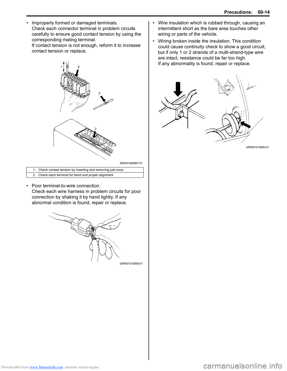
• Improperly formed or damaged terminals.Check each connector terminal in problem circuits
carefully to ensure good contact tension by using the
corresponding mating terminal.
If contact tension is not enough, reform it to increase
contact tension or replace.
• Poor terminal-to -wire connection.
Check each wire harness in problem circuits for poor
connection by shaking it by hand lightly. If any
abnormal condition is found, repair or replace. • Wire insulation which is rubbed through, causing an
intermittent short as the bare area touches other
wiring or parts of the vehicle.
• Wiring broken inside the insulation. This condition
could cause continuity check to show a good circuit,
but if only 1 or 2 strands of a multi-strand-type wire
are intact, resistance could be far too high.
If any abnormality is found, repair or replace.
1. Check contact tension by inserting and removing just once.
2. Check each terminal for bend and proper alignment.
I5RH01000007-01
I2RH01010059-01
I2RH01010060-01
Page 98 of 1496
Downloaded from www.Manualslib.com manuals search engine 1A-48 Engine General Information and Diagnosis:
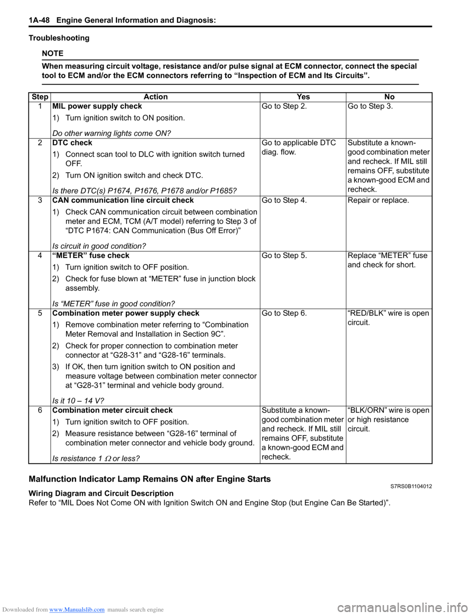
Troubleshooting
NOTE
When measuring circuit voltage, resistance and/or pulse signal at ECM connector, connect the special
tool to ECM and/or the ECM connectors referri ng to “Inspection of ECM and Its Circuits”.
Malfunction Indicator Lamp Remains ON after Engine StartsS7RS0B1104012
Wiring Diagram and Circuit Description
Refer to “MIL Does Not Come ON wit h Ignition Switch ON and Engine Stop (but Engine Can Be Started)”.
Step
Action YesNo
1 MIL power supply check
1) Turn ignition switch to ON position.
Do other warning lights come ON? Go to Step 2.
Go to Step 3.
2 DTC check
1) Connect scan tool to DLC with ignition switch turned
OFF.
2) Turn ON ignition switch and check DTC.
Is there DTC(s) P1674, P1676, P1678 and/or P1685? Go to applicable DTC
diag. flow.
Substitute a known-
good combination meter
and recheck. If MIL still
remains OFF, substitute
a known-good ECM and
recheck.
3 CAN communication line circuit check
1) Check CAN communication circuit between combination
meter and ECM, TCM (A/T model) referring to Step 3 of
“DTC P1674: CAN Communication (Bus Off Error)”
Is circuit in good condition? Go to Step 4.
Repair or replace.
4 “METER” fuse check
1) Turn ignition switch to OFF position.
2) Check for fuse blown at “M ETER” fuse in junction block
assembly.
Is “METER” fuse in good condition? Go to Step 5.
Replace “METER” fuse
and check for short.
5 Combination meter power supply check
1) Remove combination meter referring to “Combination
Meter Removal and Installation in Section 9C”.
2) Check for proper connection to combination meter connector at “G28-31” and “G28-16” terminals.
3) If OK, then turn ignition switch to ON position and measure voltage between combination meter connector
at “G28-31” terminal and vehicle body ground.
Is it 10 – 14 V? Go to Step 6.
“RED/BLK” wire is open
circuit.
6 Combination meter circuit check
1) Turn ignition switch to OFF position.
2) Measure resistance between “G28-16” terminal of
combination meter connector and vehicle body ground.
Is resistance 1
Ω or less? Substitute a known-
good combination meter
and recheck. If MIL still
remains OFF, substitute
a known-good ECM and
recheck.
“BLK/ORN” wire is open
or high resistance
circuit.
Page 180 of 1496
Downloaded from www.Manualslib.com manuals search engine 1A-130 Engine General Information and Diagnosis:
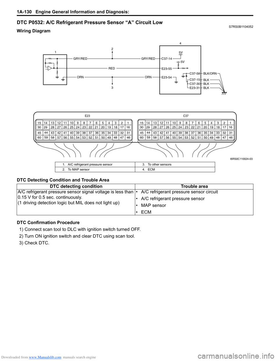
DTC P0532: A/C Refrigerant Pressure Sensor “A” Circuit LowS7RS0B1104052
Wiring Diagram
DTC Detecting Condition and Trouble Area
DTC Confirmation Procedure1) Connect scan tool to DLC with ignition switch turned OFF.
2) Turn ON ignition switch and clear DTC using scan tool.
3) Check DTC.
E23 C37
34
1819
567
1011
17
20
47 46
495051
2122
52 16
25 9
24
14
29
55
57 54 53
59
60 58 2
262728
15
30
56 4832 31
34353637
40
42 39 38
44
45 43 41 331
1213
238
34
1819
567
1011
17
20
47 46
495051
2122
52 16
25 9
24
14
29
55
57 54 53
59
60 58 2
262728
15
30
56 4832 31
34353637
40
42 39 38
44
45 43 41 331
1213
238
4
C37-58
C37-15 C37-30
BLK/ORN
BLKBLKE23-31 BLK
1
2
3
GRY/REDGRY/RED
ORNORN
5V
5VC37-14
E23-55
E23-54
RED
I6RS0C110024-03
1. A/C refrigerant pressure sensor
3. To other sensors
2. To MAP sensor 4. ECM
DTC detecting condition Trouble area
A/C refrigerant pressure sensor signal voltage is less than
0.15 V for 0.5 sec. continuously.
(1 driving detection logic but MIL does not light up) • A/C refrigerant pressure sensor circuit
• A/C refrigerant pressure sensor
• MAP sensor
•ECM
Page 182 of 1496
Downloaded from www.Manualslib.com manuals search engine 1A-132 Engine General Information and Diagnosis:
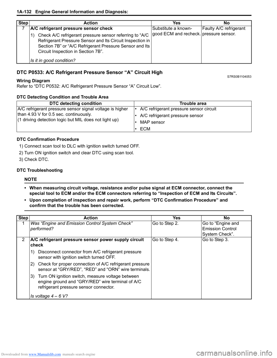
DTC P0533: A/C Refrigerant Pressure Sensor “A” Circuit HighS7RS0B1104053
Wiring Diagram
Refer to “DTC P0532: A/C Refrigerant Pressure Sensor “A” Circuit Low”.
DTC Detecting Condition and Trouble Area
DTC Confirmation Procedure1) Connect scan tool to DLC with ignition switch turned OFF.
2) Turn ON ignition switch and clear DTC using scan tool.
3) Check DTC.
DTC Troubleshooting
NOTE
• When measuring circuit voltage, resistance and/ or pulse signal at ECM connector, connect the
special tool to ECM and/or the ECM connectors re ferring to “Inspection of ECM and Its Circuits”.
• Upon completion of inspection and repair work, perform “DTC Confirmation Procedure” and confirm that the trouble has been corrected.
7 A/C refrigerant pressure sensor check
1) Check A/C refrigerant pressure sensor referring to “A/C
Refrigerant Pressure Sensor and Its Circuit Inspection in
Section 7B” or “A/C Refrigerant Pressure Sensor and Its
Circuit Inspection in Section 7B”.
Is it in good condition? Substitute a known-
good ECM and recheck.
Faulty A/C refrigerant
pressure sensor.
Step Action Yes No
DTC detecting condition
Trouble area
A/C refrigerant pressure sensor signal voltage is higher
than 4.93 V for 0.5 sec. continuously.
(1 driving detection logic but MIL does not light up) • A/C refrigerant pressure sensor circuit
• A/C refrigerant pressure sensor
• MAP sensor
•ECM
Step
Action YesNo
1 Was “Engine and Emission Control System Check”
performed? Go to Step 2.
Go to “Engine and
Emission Control
System Check”.
2 A/C refrigerant pressure sensor power supply circuit
check
1) Disconnect connector from A/C refrigerant pressure
sensor with ignition switch turned OFF.
2) Check for proper connection of A/C refrigerant pressure sensor at “GRY/RED”, “RED ” and “ORN” wire terminals.
3) Turn ON ignition switch, measure voltage between engine ground and “GRY/RED” wire terminal of A/C
refrigerant pressure sensor connector.
Is voltage 4 – 6 V? Go to Step 4.
Go to Step 3.
Page 189 of 1496
Downloaded from www.Manualslib.com manuals search engine Engine General Information and Diagnosis: 1A-139
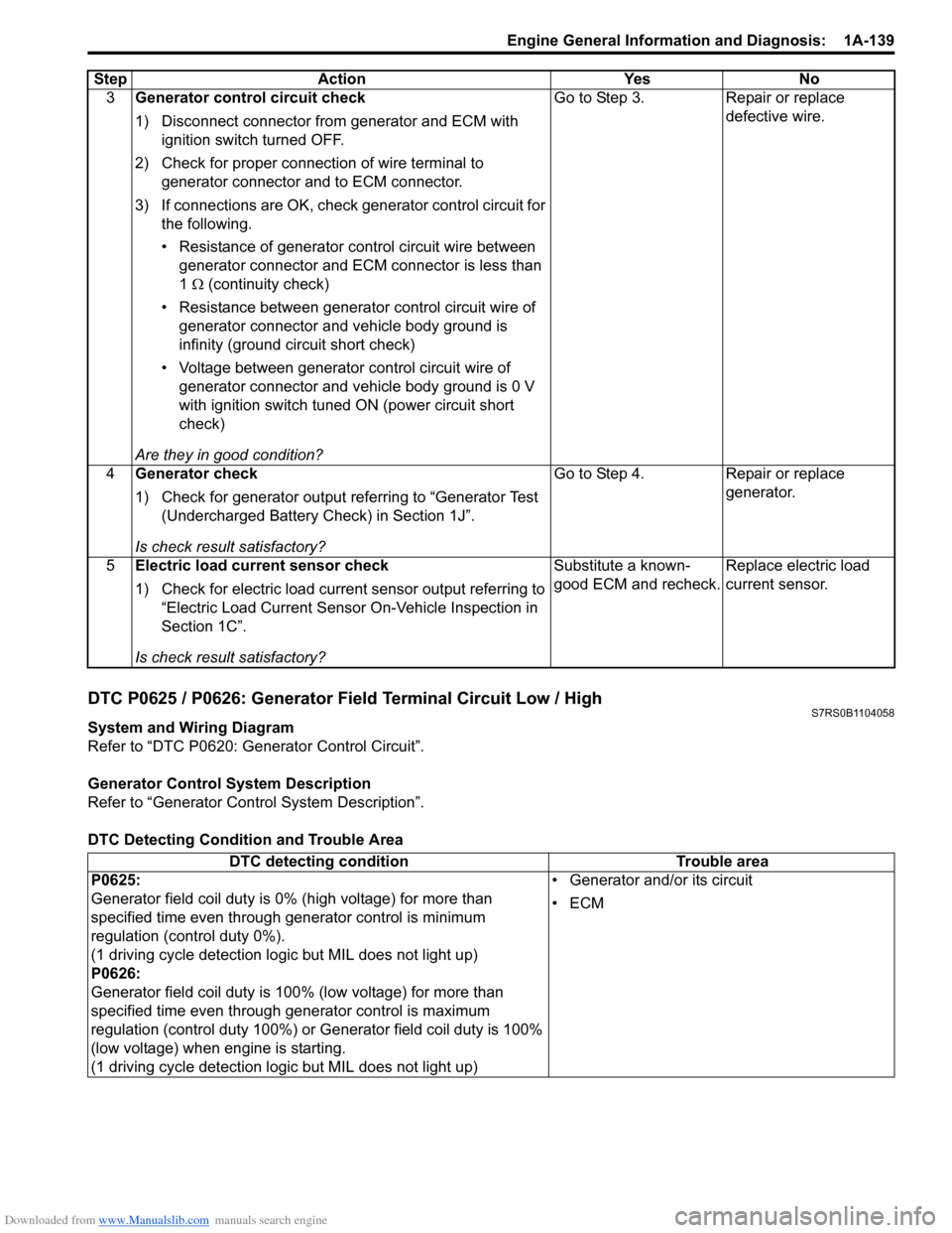
DTC P0625 / P0626: Generator Field Terminal Circuit Low / HighS7RS0B1104058
System and Wiring Diagram
Refer to “DTC P0620: Generator Control Circuit”.
Generator Control System Description
Refer to “Generator Control System Description”.
DTC Detecting Condition and Trouble Area 3
Generator control circuit check
1) Disconnect connector from generator and ECM with
ignition switch turned OFF.
2) Check for proper connection of wire terminal to generator connector and to ECM connector.
3) If connections are OK, check generator control circuit for
the following.
• Resistance of generator control circuit wire between generator connector and ECM connector is less than
1 Ω (continuity check)
• Resistance between generator control circuit wire of
generator connector and vehicle body ground is
infinity (ground circuit short check)
• Voltage between generator control circuit wire of generator connector and vehicle body ground is 0 V
with ignition switch tuned ON (power circuit short
check)
Are they in good condition? Go to Step 3. Repair or replace
defective wire.
4 Generator check
1) Check for generator output referring to “Generator Test
(Undercharged Battery Check) in Section 1J”.
Is check result satisfactory? Go to Step 4. Repair or replace
generator.
5 Electric load current sensor check
1) Check for electric load current sensor output referring to
“Electric Load Current Sensor On-Vehicle Inspection in
Section 1C”.
Is check result satisfactory? Substitute a known-
good ECM and recheck.
Replace electric load
current sensor.
Step Action Yes No
DTC detecting condition
Trouble area
P0625:
Generator field coil duty is 0% (high voltage) for more than
specified time even through generator control is minimum
regulation (control duty 0%).
(1 driving cycle detection logic but MIL does not light up)
P0626:
Generator field coil duty is 100% (low voltage) for more than
specified time even through ge nerator control is maximum
regulation (control duty 100%) or Generator field coil duty is 100%
(low voltage) when engine is starting.
(1 driving cycle detection logic but MIL does not light up) • Generator and/or its circuit
•ECM
Page 191 of 1496
Downloaded from www.Manualslib.com manuals search engine Engine General Information and Diagnosis: 1A-141
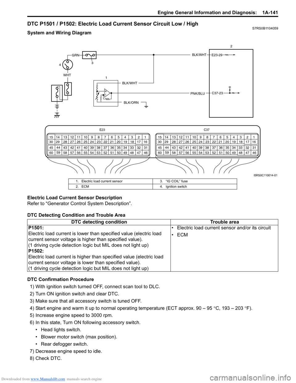
DTC P1501 / P1502: Electric Load Current Sensor Circuit Low / HighS7RS0B1104059
System and Wiring Diagram
Electric Load Current Sensor Description
Refer to “Generator Control System Description”.
DTC Detecting Condition and Trouble Area
DTC Confirmation Procedure1) With ignition switch turned OFF, connect scan tool to DLC.
2) Turn ON ignition switch and clear DTC.
3) Make sure that all accessory switch is tuned OFF.
4) Start engine and warm it up to normal operating temperature (ECT approx. 90 – 95 °C, 193 – 203 °F).
5) Increase engine speed to 3000 rpm.
6) In this state, Turn ON following accessory switch.
• Head lights switch.
• Blower motor switch (max position).
• Rear defogger switch.
7) Decrease engine speed to idle.
8) Check DTC.
E23 C37
34
1819
567
1011
17
20
47 46
495051
2122
52 16
25 9
24
14
29
55
57 54 53
59
60 58 2
262728
15
30
56 4832 31
34353637
40
42 39 38
44
45 43 41 331
1213
238
34
1819
567
1011
17
20
47 46
495051
2122
52 16
25 9
24
14
29
55
57 54 53
59
60 58 2
262728
15
30
56 4832 31
34353637
40
42 39 38
44
45 43 41 331
1213
238
BLK/WHT
WHT
GRN
4
3 2
E23-29
1
C37-23PNK/BLU
BLK/ORN
BLK/WHT
I5RS0C110014-01
1. Electric load current sensor
3. “IG COIL” fuse
2. ECM 4. Ignition switch
DTC detecting condition Trouble area
P1501:
Electric load current is lower th an specified value (electric load
current sensor voltage is higher than specified value).
(1 driving cycle detection logic but MIL does not light up)
P1502:
Electric load current is higher than specified value (electric load
current sensor voltage is lo wer than specified value).
(1 driving cycle detection logic but MIL does not light up) • Electric load current sensor and/or its circuit
•ECM