2008 SUZUKI SWIFT Fuel injection
[x] Cancel search: Fuel injectionPage 11 of 1496
Downloaded from www.Manualslib.com manuals search engine Precautions: 00-6
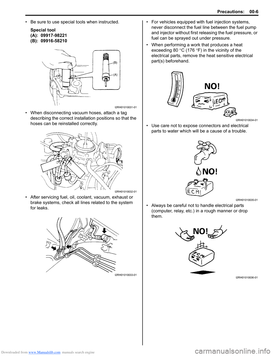
• Be sure to use special tools when instructed.Special tool
(A): 09917-98221
(B): 09916-58210
• When disconnecting vacuum hoses, attach a tag describing the correct installation positions so that the
hoses can be reinstalled correctly.
• After servicing fuel, oil, coolant, vacuum, exhaust or brake systems, check all lin es related to the system
for leaks. • For vehicles equipped with fuel injection systems,
never disconnect the fuel line between the fuel pump
and injector without first releasing the fuel pressure, or
fuel can be sprayed out under pressure.
• When performing a work that produces a heat exceeding 80 °C (176 ° F) in the vicinity of the
electrical parts, remove t he heat sensitive electrical
part(s) beforehand.
• Use care not to expose connectors and electrical parts to water which will be a cause of a trouble.
• Always be careful not to handle electrical parts (computer, relay, etc.) in a rough manner or drop
them.
I2RH01010031-01
I2RH01010032-01
I2RH01010033-01
I2RH01010034-01
I2RH01010035-01
I2RH01010036-01
Page 22 of 1496
Downloaded from www.Manualslib.com manuals search engine 0A-1 General Information:
General Information
General Information
General Description
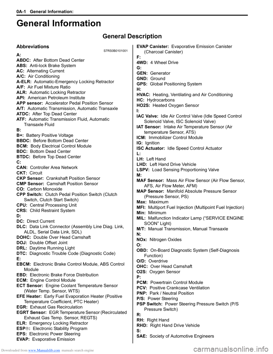
AbbreviationsS7RS0B0101001
A:
ABDC: After Bottom Dead Center
ABS: Anti-lock Brake System
AC: Alternating Current
A/C: Air Conditioning
A-ELR: Automatic-Emergency Locking Retractor
A/F: Air Fuel Mixture Ratio
ALR: Automatic Locking Retractor
API: American Petroleum Institute
APP sensor: Accelerator Pedal Position Sensor
A/T: Automatic Transmission , Automatic Transaxle
AT D C : After Top Dead Center
ATF: Automatic Transmission Fluid, Automatic
Transaxle Fluid
B:
B+: Battery Positive Voltage
BBDC: Before Bottom Dead Center
BCM: Body Electrical Control Module
BDC: Bottom Dead Center
BTDC: Before Top Dead Center
C:
CAN: Controller Area Network
CKT: Circuit
CKP Sensor: Crankshaft Position Sensor
CMP Sensor: Camshaft Position Sensor
CO: Carbon Monoxide
CPP Switch: Clutch Pedal Position Switch (Clutch
Switch, Clutch Start Switch)
CPU: Central Processing Unit
CRS: Child Restraint System
D:
DC: Direct Current
DLC: Data Link Connector (Assembly Line Diag. Link,
ALDL, Serial Data Link, SDL)
DOHC: Double Over Head Camshaft
DOJ: Double Offset Joint
DRL: Daytime Running Light
DTC: Diagnostic Trouble Code (Diagnostic Code)
E:
EBCM: Electronic Brake Cont rol Module, ABS Control
Module
EBD: Electronic Brake Force Distribution
ECM: Engine Control Module
ECT Sensor: Engine Coolant Temperature Sensor (Water Temp. Sensor, WTS)
EFE Heater: Early Fuel Evaporation Heater (Positive
Temperature Coefficient, PTC Heater)
EGR: Exhaust Gas Recirculation
EGRT Sensor: EGR Temperature Sensor (Recirculated
Exhaust Gas Temp. Sensor, REGTS)
ELR: Emergency Locking Retractor
ESP ®: Electronic Stability Program
EPS: Electronic Power Steering
EVAP: Evaporative Emission EVAP Canister:
Evaporative Emission Canister
(Charcoal Canister)
F:
4WD: 4 Wheel
Drive
G:
GEN: Generator
GND: Ground
GPS: Global Positioning System
H:
HVAC: Heating, Ventilating and Air Conditioning
HC: Hydrocarbons
HO2S: Heated Oxygen Sensor
I:
IAC Valve: Idle Air Control Valve (Idle Speed Control
Solenoid Valve, ISC Solenoid Valve)
IAT Sensor: Intake Air Temperature Sensor (Air
temperature Sensor, ATS)
ICM: Immobilizer Control Module
IG: Ignition
ISC Actuator: Idle Speed Control Actuator
L:
LH: Left Hand
LHD: Left Hand Drive Vehicle
LSPV: Load Sensing Proportioning Valve
M:
MAF Sensor: Mass Air Flow Sensor (Air Flow Sensor, AFS, Air Flow Meter, AFM)
MAP Sensor: Manifold Absolute Pressure Sensor
(Pressure Sensor, PS)
Max: Maximum
MFI: Multiport Fuel Injection (Mu ltipoint Fuel Injection)
Min: Minimum
MIL: Malfunction Indicator Lamp (“SERVICE ENGINE
SOON” Light)
M/T: Manual Transmission, Manual Transaxle
N:
NOx: Nitrogen Oxides
O:
OBD: On-Board Diagnostic System (Self-Diagnosis
Function)
O/D: Overdrive
OHC: Over Head Camshaft
O2S: Oxygen Sensor
P:
PCM: Powertrain Control Module
PCV: Positive Crankcase Ventilation
PNP: Park / Neutral Position
P/S: Power Steering
PSP Switch: Power Steering Pressure Switch (P/S
Pressure Switch)
R:
RH: Right Hand
RHD: Right Hand Drive Vehicle
S:
SAE: Society of Automotive Engineers
Page 23 of 1496
Downloaded from www.Manualslib.com manuals search engine General Information: 0A-2
SAS: Steering Angle Sensor
SDM: Sensing and Diagnostic Module (Air Bag Controller, Air bag Control Module)
SDT: Smart Diagnostic Tester
SFI: Sequential Multipor t Fuel Injection
SOHC: Single Over Head Camshaft
T:
TBI: Throttle Body Fuel Injection (Single-Point Fuel
Injection, SPI)
TCC: Torque Converter Clutch
TCM: Transmission Control Module (A/T Controller, A/T
Control Module)
TDC: Top Dead Center
TP Sensor: Throttle Position Sensor TVV:
Thermal Vacuum Valve (Thermal Vacuum
Switching Valve, TVSV, Bi metal Vacuum Switching
Valve, BVSV)
TWC: Three Way Catalytic Converter (Three Way
Catalyst)
2WD: 2 Wheel Drive
U:
USB: Universal Serial Bus
V:
VIN: Vehicle Identification Number
VSS: Vehicle Speed Sensor
VVT: Variable Valve Timing (Camshaft Position Control)
W:
WU-OC: Warm Up Oxidation Catalytic Converter
WU-TWC: Warm Up Three Way Catalytic Converter
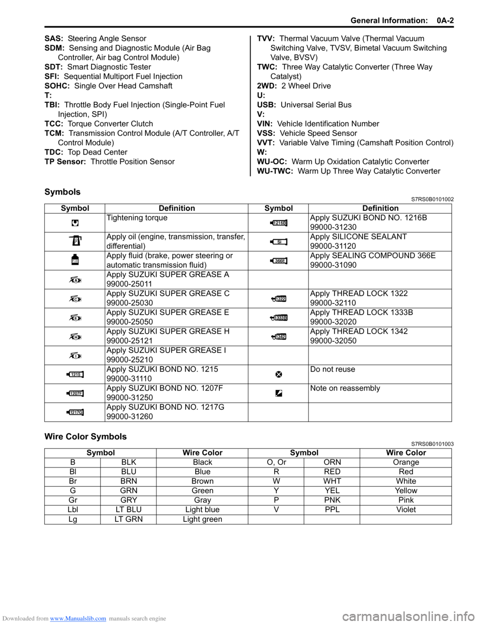
SymbolsS7RS0B0101002
Wire Color SymbolsS7RS0B0101003
Symbol Definition SymbolDefinition
Tightening torque Apply SUZUKI BOND NO. 1216B
99000-31230
Apply oil (engine, transmission, transfer,
differential) Apply SILICONE SEALANT
99000-31120
Apply fluid (brake, power steering or
automatic transmission fluid) Apply SEALING COMPOUND 366E
99000-31090
Apply SUZUKI SUPER GREASE A
99000-25011
Apply SUZUKI SUPER GREASE C
99000-25030 Apply THREAD LOCK 1322
99000-32110
Apply SUZUKI SUPER GREASE E
99000-25050 Apply THREAD LOCK 1333B
99000-32020
Apply SUZUKI SUPER GREASE H
99000-25121 Apply THREAD LOCK 1342
99000-32050
Apply SUZUKI SUPER GREASE I
99000-25210
Apply SUZUKI BOND NO. 1215
99000-31110 Do not reuse
Apply SUZUKI BO ND NO. 1207F
99000-31250 Note on reassembly
Apply SUZUKI BO ND NO. 1217G
99000-31260
Symbol Wire Color SymbolWire Color
B BLK Black O, Or ORN Orange
Bl BLU Blue RRED Red
Br BRN Brown WWHT White
G GRN Green YYEL Yellow
Gr GRY Gray PPNK Pink
Lbl LT BLU Light blueVPPL Violet
Lg LT GRN Light green
Page 62 of 1496
Downloaded from www.Manualslib.com manuals search engine 1A-12 Engine General Information and Diagnosis:
Electronic Control System DescriptionS7RS0B1101011
The electronic control system consists of 1) various sensors which detect the state of engine and driving conditions, 2)
ECM which controls various devices ac cording to the signals from the sensors and 3) various controlled devices.
Functionally, it is divided into the following sub systems:
• Fuel injection control system
• Ignition control system
• Electric throttle body control system
• Fuel pump control system
• Radiator cooling fan control system
• Evaporative emission control system
• EGR system
• Oxygen sensor heater control system
• A/C control system (A/C model)
• Camshaft position control system
• Immobilizer control system
• Generator control system
• Controller (computer) communication system
Especially, ECM, BCM, combination meter, TCM (A/T model), ABS/ESP ® control module, steering angle sensor
(ESP® model) and keyless start control module (if equipped) intercommunicate by means of CAN communication.
Page 81 of 1496
Downloaded from www.Manualslib.com manuals search engine Engine General Information and Diagnosis: 1A-31
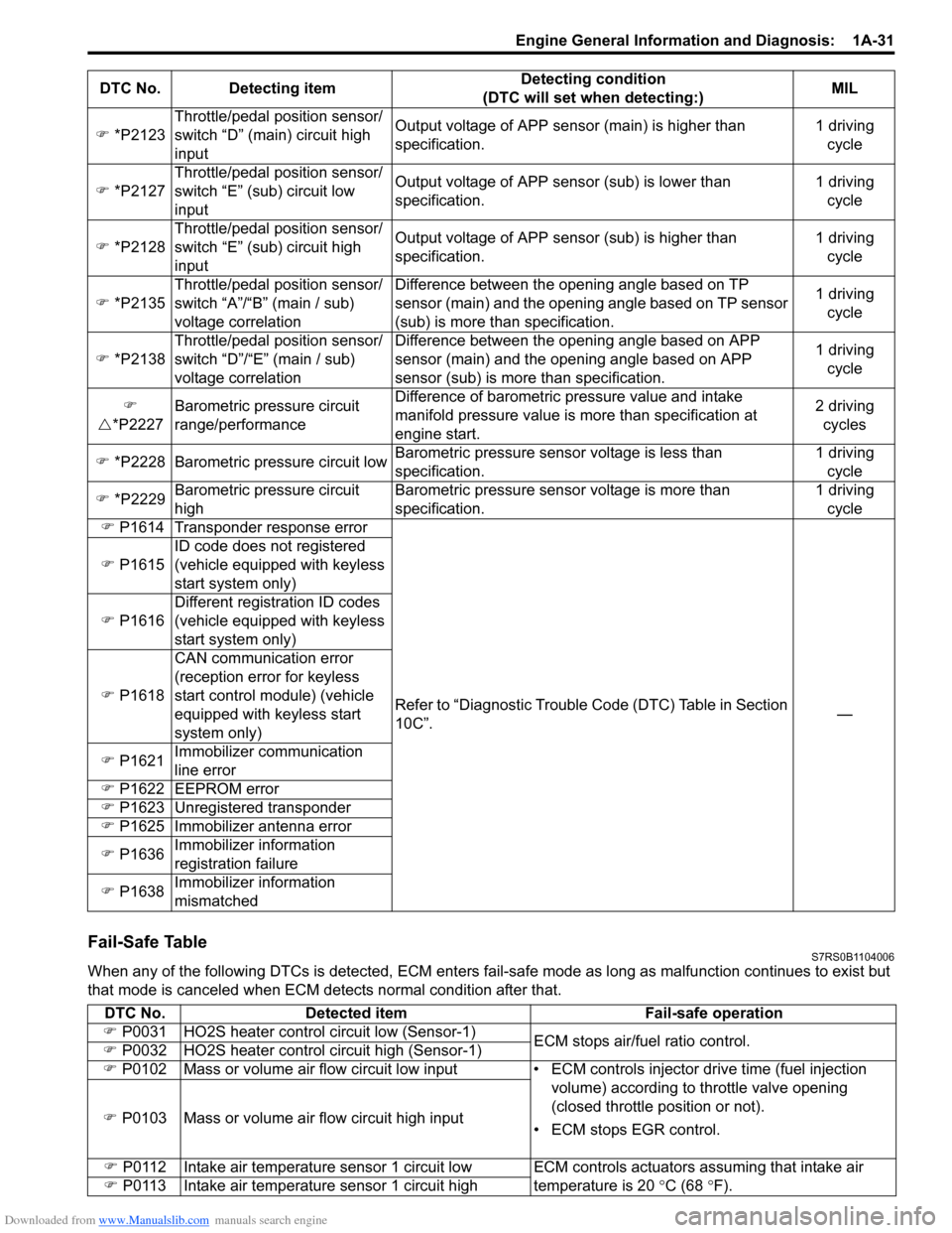
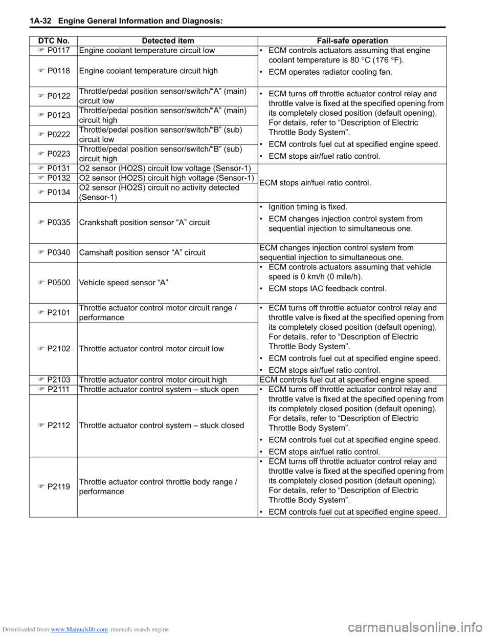
Fail-Safe TableS7RS0B1104006
When any of the following DTCs is detected, ECM enters fail-safe mode as long as malfunction continues to exist but
that mode is canceled when ECM de tects normal condition after that.
�)
*P2123 Throttle/pedal position sensor/
switch “D” (main) circuit high
input Output voltage of APP sensor (main) is higher than
specification.
1 driving
cycle
�) *P2127 Throttle/pedal position sensor/
switch “E” (sub) circuit low
input Output voltage of APP sens
or (sub) is lower than
specification. 1 driving
cycle
�) *P2128 Throttle/pedal position sensor/
switch “E” (sub) circuit high
input Output voltage of APP sensor (sub) is higher than
specification.
1 driving
cycle
�) *P2135 Throttle/pedal position sensor/
switch “A”/“B” (main / sub)
voltage correlation Difference between the opening angle based on TP
sensor (main) and the opening angle based on TP sensor
(sub) is more than specification.
1 driving
cycle
�) *P2138 Throttle/pedal position sensor/
switch “D”/“E” (main / sub)
voltage correlation Difference between the opening angle based on APP
sensor (main) and the opening angle based on APP
sensor (sub) is more
than specification. 1 driving
cycle
�)
�U *P2227 Barometric pressure circuit
range/performance Difference of barometric pressure value and intake
manifold pressure value is
more than specification at
engine start. 2 driving
cycles
�) *P2228 Barometric pressure circuit low Barometric pressure sens
or voltage is less than
specification. 1 driving
cycle
�) *P2229 Barometric pressure circuit
high Barometric pressure sensor voltage is more than
specification. 1 driving
cycle
�) P1614 Transponder response error
Refer to “Diagnostic Trouble Code (DTC) Table in Section
10C”. —
�) P1615 ID code does not registered
(vehicle equipped with keyless
start system only)
�) P1616 Different registration ID codes
(vehicle equipped with keyless
start system only)
�) P1618 CAN communication error
(reception error for keyless
start control module) (vehicle
equipped with keyless start
system only)
�) P1621 Immobilizer communication
line error
�) P1622
EEPROM error
�) P1623 Unregistered transponder
�) P1625 Immobilizer antenna error
�) P1636 Immobilizer information
registration failure
�) P1638 Immobilizer information
mismatched
DTC No. Detecting item
Detecting condition
(DTC will set when detecting:) MIL
DTC No.
Detected item Fail-safe operation
�) P0031 HO2S heater control circuit low (Sensor-1)
ECM stops air/fuel ratio control.
�) P0032 HO2S heater control circuit high (Sensor-1)
�) P0102 Mass or volume air flow circuit low input • ECM controls injector drive time (fuel injection
volume) according to throttle valve opening
(closed throttle position or not).
• ECM stops EGR control.
�)
P0103 Mass or volume air flow circuit high input
�) P0112 Intake air temperature sensor 1 circuit low ECM controls actuators assuming that intake air
temperature is 20 °C (68 ° F).
�) P0113 Intake air temperature sensor 1 circuit high
Page 82 of 1496
Downloaded from www.Manualslib.com manuals search engine 1A-32 Engine General Information and Diagnosis:
�) P0117 Engine coolant temperature circuit low • EC M controls actuators assuming that engine
coolant temperature is 80 °C (176 °F).
• ECM operates radiator cooling fan.
�)
P0118 Engine coolant temperature circuit high
�) P0122 Throttle/pedal position sensor/switch/“A” (main)
circuit low • ECM turns off throttle actuator control relay and
throttle valve is fixed at the specified opening from
its completely closed position (default opening).
For details, refer to “Description of Electric
Throttle Body System”.
• ECM controls fuel cut at specified engine speed.
• ECM stops air/fuel ratio control.
�)
P0123 Throttle/pedal position sensor/switch/“A” (main)
circuit high
�) P0222 Throttle/pedal position sensor/switch/“B” (sub)
circuit low
�) P0223 Throttle/pedal position sensor/switch/“B” (sub)
circuit high
�) P0131 O2 sensor (HO2S) circuit low voltage (Sensor-1)
ECM stops air/fuel ratio control.
�)
P0132 O2 sensor (HO2S) circuit high voltage (Sensor-1)
�) P0134 O2 sensor (HO2S) circuit no activity detected
(Sensor-1)
�) P0335 Crankshaft position sensor “A” circuit • Ignition timing is fixed.
• ECM changes injection control system from
sequential injection to simultaneous one.
�) P0340 Camshaft position sensor “A” circuit ECM changes injection
control system from
sequential injection to simultaneous one.
�) P0500 Vehicle speed sensor “A” • ECM controls actuators assuming that vehicle
speed is 0 km/h (0 mile/h).
• ECM stops IAC feedback control.
�) P2101 Throttle actuator control motor circuit range /
performance • ECM turns off throttle actuator control relay and
throttle valve is fixed at the specified opening from
its completely closed position (default opening).
For details, refer to “Description of Electric
Throttle Body System”.
• ECM controls fuel cut at specified engine speed.
• ECM stops air/fuel ratio control.
�)
P2102 Throttle actuator control motor circuit low
�) P2103 Throttle actuator control motor circuit high ECM controls fuel cut at specified engine speed.
�) P2111 Throttle actuator control system – stuck open • EC M turns off throttle actuator control relay and
throttle valve is fixed at the specified opening from
its completely closed position (default opening).
For details, refer to “Description of Electric
Throttle Body System”.
• ECM controls fuel cut at specified engine speed.
• ECM stops air/fuel ratio control.
�)
P2112 Throttle actuator control system – stuck closed
�) P2119 Throttle actuator control throttle body range /
performance • ECM turns off throttle actuator control relay and
throttle valve is fixed at the specified opening from
its completely closed position (default opening).
For details, refer to “Description of Electric
Throttle Body System”.
• ECM controls fuel cut at specified engine speed.
DTC No.
Detected item Fail-safe operation
Page 85 of 1496
Downloaded from www.Manualslib.com manuals search engine Engine General Information and Diagnosis: 1A-35
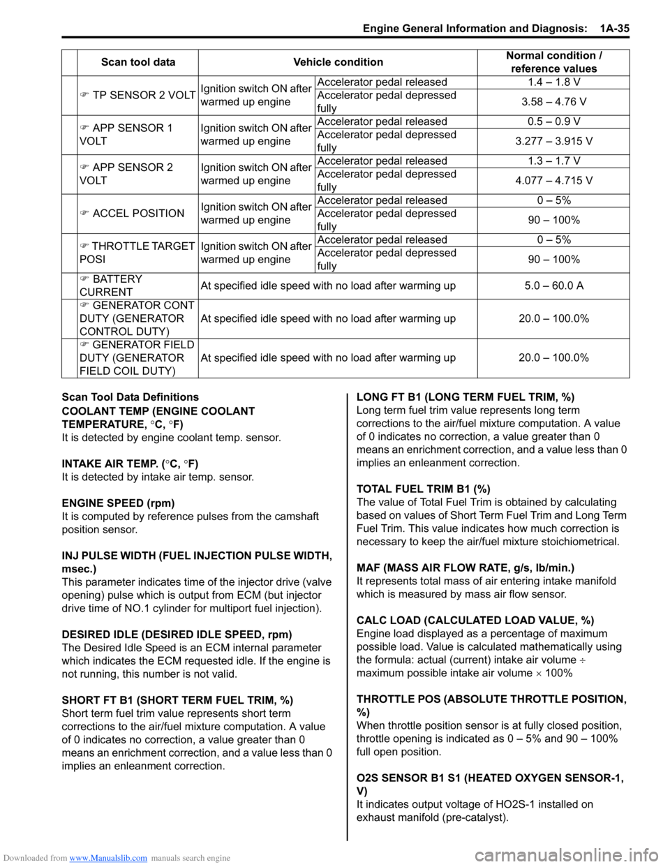
Scan Tool Data Definitions
COOLANT TEMP (ENGINE COOLANT
TEMPERATURE, °C, °F)
It is detected by engine coolant temp. sensor.
INTAKE AIR TEMP. ( °C, °F)
It is detected by intake air temp. sensor.
ENGINE SPEED (rpm)
It is computed by reference pulses from the camshaft
position sensor.
INJ PULSE WIDTH (FUEL INJECTION PULSE WIDTH,
msec.)
This parameter indicates time of the injector drive (valve
opening) pulse which is output from ECM (but injector
drive time of NO.1 cylinder fo r multiport fuel injection).
DESIRED IDLE (DESIRED IDLE SPEED, rpm)
The Desired Idle Speed is an ECM internal parameter
which indicates the ECM requested idle. If the engine is
not running, this number is not valid.
SHORT FT B1 (SHORT TERM FUEL TRIM, %)
Short term fuel trim valu e represents short term
corrections to the air/fuel mixture computation. A value
of 0 indicates no correction, a value greater than 0
means an enrichment correction, and a value less than 0
implies an enleanment correction. LONG FT B1 (LONG TERM FUEL TRIM, %)
Long term fuel trim value represents long term
corrections to the air/fuel mixture computation. A value
of 0 indicates no correction, a value greater than 0
means an enrichment correction, and a value less than 0
implies an enleanment correction.
TOTAL FUEL TRIM B1 (%)
The value of Total Fuel Trim is obtained by calculating
based on values of Short Term Fuel Trim and Long Term
Fuel Trim. This value indica
tes how much correction is
necessary to keep the air/fuel mixture stoichiometrical.
MAF (MASS AIR FLOW RATE, g/s, lb/min.)
It represents total mass of air entering intake manifold
which is measured by mass air flow sensor.
CALC LOAD (CALCULATED LOAD VALUE, %)
Engine load displayed as a percentage of maximum
possible load. Value is calculated mathematically using
the formula: actual (current) intake air volume ÷
maximum possible intake air volume × 100%
THROTTLE POS (ABSOLUTE THROTTLE POSITION,
%)
When throttle position sensor is at fully closed position,
throttle opening is indicated as 0 – 5% and 90 – 100%
full open position.
O2S SENSOR B1 S1 (HEA TED OXYGEN SENSOR-1,
V)
It indicates output voltage of HO2S-1 installed on
exhaust manifold (pre-catalyst).
�)
TP SENSOR 2 VOLT Ignition switch ON after
warmed up engine Accelerator pedal released
1.4 – 1.8 V
Accelerator pedal depressed
fully 3.58 – 4.76 V
�) APP SENSOR 1
VOLT Ignition switch ON after
warmed up engineAccelerator pedal released
0.5 – 0.9 V
Accelerator pedal depressed
fully 3.277 – 3.915 V
�) APP SENSOR 2
VOLT Ignition switch ON after
warmed up engineAccelerator pedal released
1.3 – 1.7 V
Accelerator pedal depressed
fully 4.077 – 4.715 V
�) ACCEL POSITION Ignition switch ON after
warmed up engine Accelerator pedal released
0 – 5%
Accelerator pedal depressed
fully 90 – 100%
�) THROTTLE TARGET
POSI Ignition switch ON after
warmed up engineAccelerator pedal released
0 – 5%
Accelerator pedal depressed
fully 90 – 100%
�) BATTERY
CURRENT At specified idle speed with no load after warming up
5.0 – 60.0 A
�) GENERATOR CONT
DUTY (GENERATOR
CONTROL DUTY) At specified idle speed with no load after warming up
20.0 – 100.0%
�) GENERATOR FIELD
DUTY (GENERATOR
FIELD COIL DUTY) At spe
cified idle speed with no load after warming up
20.0 – 100.0%
Scan tool data
Vehicle condition Normal condition /
reference values
Page 86 of 1496
Downloaded from www.Manualslib.com manuals search engine 1A-36 Engine General Information and Diagnosis:
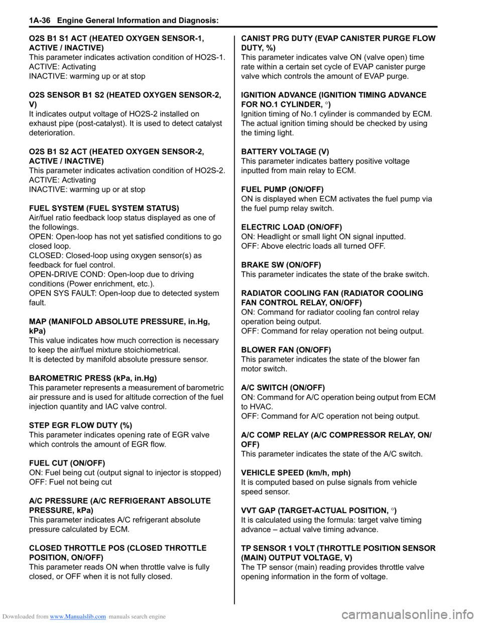
O2S B1 S1 ACT (HEATED OXYGEN SENSOR-1,
ACTIVE / INACTIVE)
This parameter indicates activation condition of HO2S-1.
ACTIVE: Activating
INACTIVE: warming up or at stop
O2S SENSOR B1 S2 (HEATED OXYGEN SENSOR-2,
V)
It indicates output voltage of HO2S-2 installed on
exhaust pipe (post-catalyst). It is used to detect catalyst
deterioration.
O2S B1 S2 ACT (HEATED OXYGEN SENSOR-2,
ACTIVE / INACTIVE)
This parameter indicates acti vation condition of HO2S-2.
ACTIVE: Activating
INACTIVE: warming up or at stop
FUEL SYSTEM (FUEL SYSTEM STATUS)
Air/fuel ratio feedback loop status displayed as one of
the followings.
OPEN: Open-loop has not yet satisfied conditions to go
closed loop.
CLOSED: Closed-loop using oxygen sensor(s) as
feedback for fuel control.
OPEN-DRIVE COND: Open-loop due to driving
conditions (Power enrichment, etc.).
OPEN SYS FAULT: Open-loop due to detected system
fault.
MAP (MANIFOLD ABSOLUTE PRESSURE, in.Hg,
kPa)
This value indicates how much correction is necessary
to keep the air/fuel mixture stoichiometrical.
It is detected by manifold absolute pressure sensor.
BAROMETRIC PRESS (kPa, in.Hg)
This parameter represents a measurement of barometric
air pressure and is used for al titude correction of the fuel
injection quantity and IAC valve control.
STEP EGR FLOW DUTY (%)
This parameter indicates opening rate of EGR valve
which controls the amount of EGR flow.
FUEL CUT (ON/OFF)
ON: Fuel being cut (output signal to injector is stopped)
OFF: Fuel not being cut
A/C PRESSURE (A/C REFRIGERANT ABSOLUTE
PRESSURE, kPa)
This parameter indicates A/C refrigerant absolute
pressure calculated by ECM.
CLOSED THROTTLE PO S (CLOSED THROTTLE
POSITION, ON/OFF)
This parameter reads ON wh en throttle valve is fully
closed, or OFF when it is not fully closed. CANIST PRG DUTY (EVAP CANISTER PURGE FLOW
DUTY, %)
This parameter indicates valve ON (valve open) time
rate within a certain set cycle of EVAP canister purge
valve which controls the amount of EVAP purge.
IGNITION ADVANCE (IGNITION TIMING ADVANCE
FOR NO.1 CYLINDER,
°)
Ignition timing of No.1 cylinder is commanded by ECM.
The actual ignition timing should be checked by using
the timing light.
BATTERY VOLTAGE (V)
This parameter indicates battery positive voltage
inputted from main relay to ECM.
FUEL PUMP (ON/OFF)
ON is displayed when ECM activates the fuel pump via
the fuel pump relay switch.
ELECTRIC LOAD (ON/OFF)
ON: Headlight or small light ON signal inputted.
OFF: Above electric loads all turned OFF.
BRAKE SW (ON/OFF)
This parameter indicates the state of the brake switch.
RADIATOR COOLING FAN (RADIATOR COOLING
FAN CONTROL RELAY, ON/OFF)
ON: Command for radiator cooling fan control relay
operation being output.
OFF: Command for relay operation not being output.
BLOWER FAN (ON/OFF)
This parameter indicates the state of the blower fan
motor switch.
A/C SWITCH (ON/OFF)
ON: Command for A/C operatio n being output from ECM
to HVAC.
OFF: Command for A/C oper ation not being output.
A/C COMP RELAY (A/C COMPRESSOR RELAY, ON/
OFF)
This parameter indicates the state of the A/C switch.
VEHICLE SPEED (km/h, mph)
It is computed based on pulse signals from vehicle
speed sensor.
VVT GAP (TARGET-ACTUAL POSITION, °)
It is calculated using the formula: target valve timing
advance – actual valve timing advance.
TP SENSOR 1 VOLT (THROTTLE POSITION SENSOR
(MAIN) OUTPUT VOLTAGE, V)
The TP sensor (main) reading provides throttle valve
opening information in the form of voltage.