2008 SUZUKI SWIFT Electronic power steering
[x] Cancel search: Electronic power steeringPage 4 of 1496

Downloaded from www.Manualslib.com manuals search engine 00
0
1
2
3
4
5
6
7
8
9
10
11
Vo l u m e 1
Precautions............................................................... 00-iPrecautions ............................................................ 00-1
General Information ................ ................................... 0-i
General Information ............................................... 0A-1
Maintenance and Lubricatio n ................................. 0B-1
Engine ......................................................................... 1-i Precautions .............................................................. 1-1
Engine General Information and Diagnosis ........... 1A-1
Aux. Emission Control Devices .............................. 1B-1
Engine Electrical Devices....................................... 1C-1
Engine Mechanical ................................................. 1D-1
Engine Lubrication System .................................... 1E-1
Engine Cooling System .......................................... 1F-1
Fuel System ...........................................................1G-1
Ignition System....................................................... 1H-1
Starting System ....................................................... 1I-1
Charging System.....................................................1J-1
Exhaust System ..................................................... 1K-1
Suspension ................................................................. 2-i Precautions .............................................................. 2-1
Suspension General Diagnosis .............................. 2A-1
Front Suspension ................................................... 2B-1
Rear Suspension................ .................................... 2C-1
Wheels and Tires ................................................... 2D-1
Driveline / Axle ........................................................... 3-i Precautions .............................................................. 3-1
Drive Shaft / Axle ................................................... 3A-1
Brakes ......................................................................... 4-i Precautions .............................................................. 4-1
Brake Control System and Diagnosis .................... 4A-1
Front Brakes........................................................... 4B-1
Rear Brakes ........................................................... 4C-1
Parking Brake......................................................... 4D-1
ABS ........................................................................ 4E-1
Electronic Stability Program ................................... 4F-1
Vo l u m e 2
Precautions ............................................................... 00-iPrecautions ............................................................ 00-1
Transmission / Transaxle .... ...................................... 5-i
Precautions .............................................................. 5-1
Automatic Transmission/Transaxle ........................ 5A-1
Manual Transmission/Transaxle ............................ 5B-1
Clutch .....................................................................5C-1
Steering ....................................................................... 6-i Precautions .............................................................. 6-1
Steering General Diagnosis ................................... 6A-1
Steering Wheel and Column .................................. 6B-1
Power Assisted Steering System ...........................6C-1
HVAC ........................................................................... 7-i Precautions .............................................................. 7-1
Heater and Ventilation............................................ 7A-1
Air Conditioning System ......................................... 7B-1
Restraint ...................................................................... 8-i Precautions .............................................................. 8-1
Seat Belts ............................................................... 8A-1
Air Bag System ...................................................... 8B-1
Body, Cab and Accessories .... .................................. 9-i
Precautions .............................................................. 9-1
Wiring Systems ...................................................... 9A-1
Lighting Systems .................................................... 9B-1
Instrumentation / Driver Info. / Horn .......................9C-1
Wipers / Washers ...................................................9D-1
Glass / Windows / Mirrors ...................................... 9E-1
Security and Locks ................................................. 9F-1
Seats ..................................................................... 9G-1
Interior Trim ............................................................9H-1
Hood / Fenders / Doors .......................................... 9J-1
Body Structure ....................................................... 9K-1
Paint / Coatings ...................................................... 9L-1
Exterior Trim .......................................................... 9M-1
Control Systems ....................................................... 10-i Precautions ............................................................ 10-1
Body Electrical Control Sy stem ............................ 10B-1
Immobilizer Control System .................................10C-1
Keyless Start System ........................................... 10E-1
TABLE OF CONTENTS
Page 22 of 1496
Downloaded from www.Manualslib.com manuals search engine 0A-1 General Information:
General Information
General Information
General Description
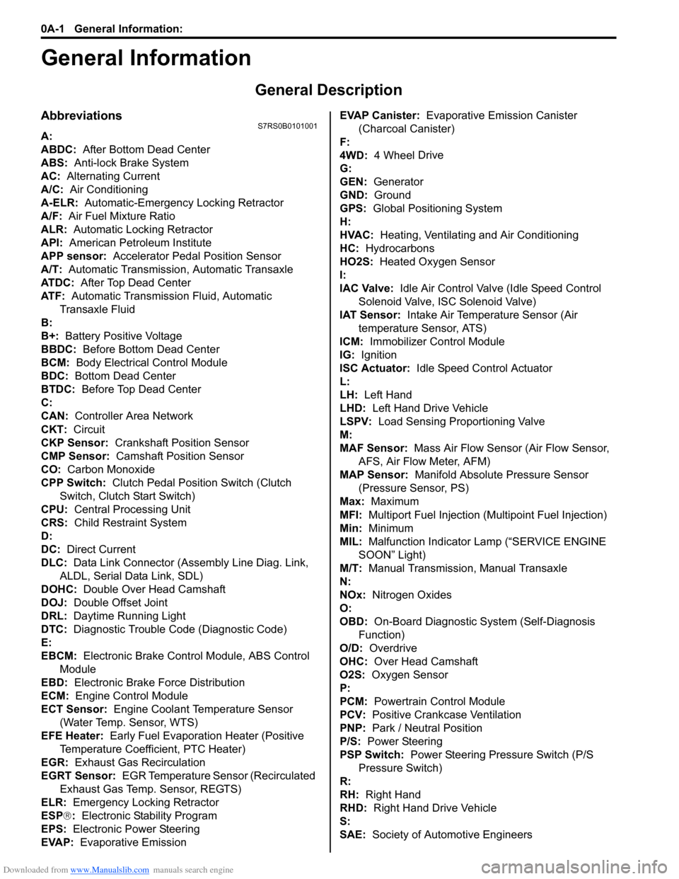
AbbreviationsS7RS0B0101001
A:
ABDC: After Bottom Dead Center
ABS: Anti-lock Brake System
AC: Alternating Current
A/C: Air Conditioning
A-ELR: Automatic-Emergency Locking Retractor
A/F: Air Fuel Mixture Ratio
ALR: Automatic Locking Retractor
API: American Petroleum Institute
APP sensor: Accelerator Pedal Position Sensor
A/T: Automatic Transmission , Automatic Transaxle
AT D C : After Top Dead Center
ATF: Automatic Transmission Fluid, Automatic
Transaxle Fluid
B:
B+: Battery Positive Voltage
BBDC: Before Bottom Dead Center
BCM: Body Electrical Control Module
BDC: Bottom Dead Center
BTDC: Before Top Dead Center
C:
CAN: Controller Area Network
CKT: Circuit
CKP Sensor: Crankshaft Position Sensor
CMP Sensor: Camshaft Position Sensor
CO: Carbon Monoxide
CPP Switch: Clutch Pedal Position Switch (Clutch
Switch, Clutch Start Switch)
CPU: Central Processing Unit
CRS: Child Restraint System
D:
DC: Direct Current
DLC: Data Link Connector (Assembly Line Diag. Link,
ALDL, Serial Data Link, SDL)
DOHC: Double Over Head Camshaft
DOJ: Double Offset Joint
DRL: Daytime Running Light
DTC: Diagnostic Trouble Code (Diagnostic Code)
E:
EBCM: Electronic Brake Cont rol Module, ABS Control
Module
EBD: Electronic Brake Force Distribution
ECM: Engine Control Module
ECT Sensor: Engine Coolant Temperature Sensor (Water Temp. Sensor, WTS)
EFE Heater: Early Fuel Evaporation Heater (Positive
Temperature Coefficient, PTC Heater)
EGR: Exhaust Gas Recirculation
EGRT Sensor: EGR Temperature Sensor (Recirculated
Exhaust Gas Temp. Sensor, REGTS)
ELR: Emergency Locking Retractor
ESP ®: Electronic Stability Program
EPS: Electronic Power Steering
EVAP: Evaporative Emission EVAP Canister:
Evaporative Emission Canister
(Charcoal Canister)
F:
4WD: 4 Wheel
Drive
G:
GEN: Generator
GND: Ground
GPS: Global Positioning System
H:
HVAC: Heating, Ventilating and Air Conditioning
HC: Hydrocarbons
HO2S: Heated Oxygen Sensor
I:
IAC Valve: Idle Air Control Valve (Idle Speed Control
Solenoid Valve, ISC Solenoid Valve)
IAT Sensor: Intake Air Temperature Sensor (Air
temperature Sensor, ATS)
ICM: Immobilizer Control Module
IG: Ignition
ISC Actuator: Idle Speed Control Actuator
L:
LH: Left Hand
LHD: Left Hand Drive Vehicle
LSPV: Load Sensing Proportioning Valve
M:
MAF Sensor: Mass Air Flow Sensor (Air Flow Sensor, AFS, Air Flow Meter, AFM)
MAP Sensor: Manifold Absolute Pressure Sensor
(Pressure Sensor, PS)
Max: Maximum
MFI: Multiport Fuel Injection (Mu ltipoint Fuel Injection)
Min: Minimum
MIL: Malfunction Indicator Lamp (“SERVICE ENGINE
SOON” Light)
M/T: Manual Transmission, Manual Transaxle
N:
NOx: Nitrogen Oxides
O:
OBD: On-Board Diagnostic System (Self-Diagnosis
Function)
O/D: Overdrive
OHC: Over Head Camshaft
O2S: Oxygen Sensor
P:
PCM: Powertrain Control Module
PCV: Positive Crankcase Ventilation
PNP: Park / Neutral Position
P/S: Power Steering
PSP Switch: Power Steering Pressure Switch (P/S
Pressure Switch)
R:
RH: Right Hand
RHD: Right Hand Drive Vehicle
S:
SAE: Society of Automotive Engineers
Page 576 of 1496
Downloaded from www.Manualslib.com manuals search engine 4F-2 Electronic Stability Program:
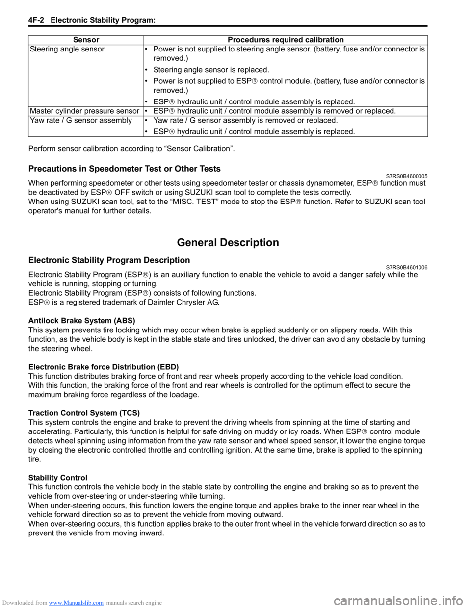
Perform sensor calibration according to “Sensor Calibration”.
Precautions in Speedometer Test or Other TestsS7RS0B4600005
When performing speedometer or other tests using speedometer tester or chassis dynamometer, ESP® function must
be deactivated by ESP ® OFF switch or using SUZUKI scan to ol to complete the tests correctly.
When using SUZUKI scan tool, set to the “MISC. TEST” mode to stop the ESP ® function. Refer to SUZUKI scan tool
operator's manual for further details.
General Description
Electronic Stability Program DescriptionS7RS0B4601006
Electronic Stability Program (ESP ®) is an auxiliary function to enable the vehicle to av oid a danger safely while the
vehicle is running, stopping or turning.
Electronic Stability Program (ESP ®) consists of following functions.
ESP ® is a registered trademark of Daimler Chrysler AG.
Antilock Brake System (ABS)
This system prevents tire locking which may occur when br ake is applied suddenly or on slippery roads. With this
function, as the vehicle body is kept in the stable state an d tires unlocked, the driver can avoid any obstacle by turning
the steering wheel.
Electronic Brake force Distribution (EBD)
This function distributes braking force of front and rear wheels properly according to the vehicle load condition.
With this function, the braking force of the front and rear wheels is controlled for the optimum effect to secure the
maximum braking force regardless of the loadage.
Traction Control System (TCS)
This system controls the engine and brake to prevent the dr iving wheels from spinning at the time of starting and
accelerating. Particularly, this fu nction is helpful for safe driving on muddy or icy roads. When ESP ® control module
detects wheel spinning using information from the yaw rate sensor and wheel speed sensor, it lower the engine torque
by closing the electronic controlled thro ttle and controlling ignition. At the same time, brake is applied to the spinning
tire.
Stability Control
This function controls the vehicle body in the stable state by controlling the engine and braking so as to prevent the
vehicle from over-steering or under-steering while turning.
When under-steering occurs, this function lowers the engine torque and applies brake to the inner rear wheel in the
vehicle forward direction so as to pr event the vehicle from moving outward.
When over-steering occurs, this function applies brake to the outer front wheel in the vehicle forward direction so as to
prevent the vehicle from moving inward. Sensor Procedures required calibration
Steering angle sensor • Power is not su pplied to steering angle sensor. (battery, fuse and/or connector is
removed.)
• Steering angle sensor is replaced.
• Power is not supplied to ESP ® control module. (battery, fuse and/or connector is
removed.)
• ESP® hydraulic unit / control module assembly is replaced.
Master cylinder pressure sensor • ESP® hydraulic unit / control module assembly is removed or replaced.
Yaw rate / G sensor assembly • Yaw rate / G sensor assembly is removed or replaced.
• ESP® hydraulic unit / control module assembly is replaced.
Page 582 of 1496
Downloaded from www.Manualslib.com manuals search engine 4F-8 Electronic Stability Program:
Schematic and Routing Diagram
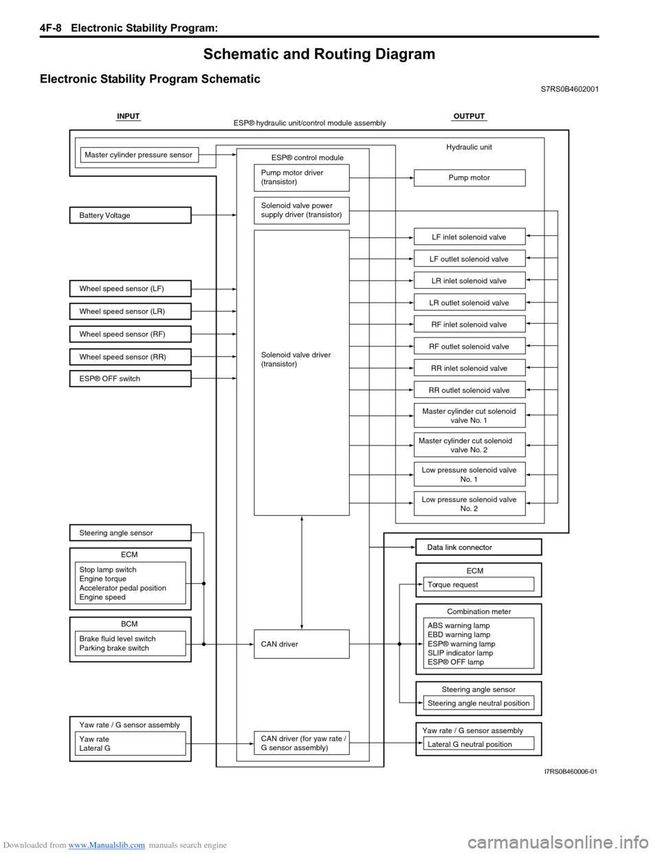
Electronic Stability Program SchematicS7RS0B4602001
INPUTOUTPUT
ESP® control module
Wheel speed sensor (LF)
Wheel speed sensor (LR)
Wheel speed sensor (RF) Battery VoltageMaster cylinder pressure sensor
Pump motor driver
(transistor)
Solenoid valve power
supply driver (transistor)
Solenoid valve driver
(transistor)
CAN driver
CAN driver (for yaw rate /
G sensor assembly) Hydraulic unit
Pump motor
LF inlet solenoid valve
LF outlet solenoid valve
LR inlet solenoid valve
LR outlet solenoid valve
RF inlet solenoid valve
RF outlet solenoid valve
RR inlet solenoid valve
RR outlet solenoid valve
Data link connector
Data link connector
ESP® hydraulic unit/control module assembly
Wheel speed sensor (RR)
Master cylinder cut solenoid valve No. 1
Master cylinder cut solenoid
valve No. 2
Low pressure solenoid valve No. 1
Low pressure solenoid valveNo. 2
Stop lamp switch
Engine torque
Accelerator pedal position
Engine speed ECM
Brake fluid level switch
Parking brake switch
BCM
Steering angle sensor
ESP® OFF switch
Yaw rate
Lateral G Yaw rate / G sensor assembly
ABS warning lamp
EBD warning lamp
ESP® warning lamp
SLIP indicator lamp
ESP® OFF lampCombination meter
Torque request
ECM
Steering angle neutral positionSteering angle sensor
Yaw rate / G sensor assembly
Lateral G neutral position
I7RS0B460006-01
Page 583 of 1496
Downloaded from www.Manualslib.com manuals search engine Electronic Stability Program: 4F-9
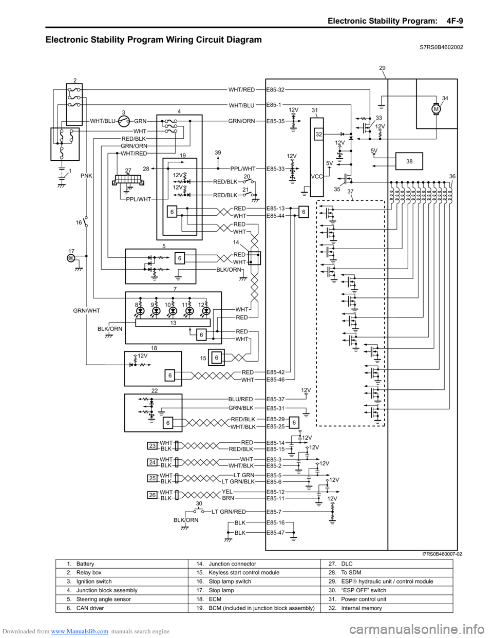
Electronic Stability Program Wiring Circuit DiagramS7RS0B4602002
WHT/BLU
WHT/BLUGRN
M
12V3
12V
5V
12V
VCC
WHT/RED
WHT
7
REDWHT
12V
12V
6 19
20
21RED/BLK
RED/BLK
GRN/WHT
PNK
12V
GRN/BLK
5V
LT GRN/RED
BLK/ORN
4
16
17
186
22
6 29
30 34
36
38
33
35
32
31
6
6 37
BLK
BLK
RED/BLKRED12V
BLKWHT
23
WHT/BLKWHT
12V
BLKWHT
24
BLKWHTLT GRN/BLKLT GRN
12V
25
BLKWHTBRN
12V
26YEL
12V
98101211
13
6BLK/ORN
1
227
5
WHT/REDGRN/ORN
BLK/ORN
REDWHT
REDWHT
PPL/WHT
6
REDWHT
REDWHT
6
REDWHT
RED/BLK
PPL/WHT
28
39
15 14
BLU/RED
GRN/ORN
12V
12V
E85-35
E85-33
E85-13E85-44
E85-46
E85-29E85-25
E85-37
E85-31
E85-14E85-15
E85-12E85-11
E85-16
E85-47
E85-3
E85-32
E85-1
E85-2
E85-5E85-6
E85-7
E85-42
RED/BLKWHT/BLK
I7RS0B460007-02
1. Battery 14. Junction connector 27. DLC
2. Relay box 15. Keyless start control module 28. To SDM
3. Ignition switch 16. Stop lamp switch 29. ESP® hydraulic unit / control module
4. Junction block assembly 17. Stop lamp 30. “ESP OFF” switch
5. Steering angle sensor 18. ECM 31. Power control unit
6. CAN driver 19. BCM (included in junction block assembly) 32. Internal memory
Page 590 of 1496

Downloaded from www.Manualslib.com manuals search engine 4F-16 Electronic Stability Program:
�) C1022 Right-front wheel speed
sensor or encoder failure Abnormal wheel speed sensor
signal is detected.
�{
*1 �{
�) C1023 Yaw rate sensor failure • Yaw rate sensor signal is out of
range.
• Vehicle behavior and yaw rate signal is disagreed. ——
�{
�) C1024 Steering angle sensor circuit
failure • Steering angle sensor internal
defect is detected by CPU in
steering angle sensor.
• Steering angle sensor signal is out of specified range. ——
�{
�) C1025 Left-front wheel speed
sensor circuit failure Wheel sensor signal is out of
specified range.
�{
*1 �{
�) C1026 Left-front wheel speed
sensor or encoder failure Abnormal wheel speed sensor
signal is detected.
�{
*1 �{
�) C1027 ESP
® OFF switch circuit
failure Mechanical switch failure, failure in
switch wiring is shorted to ground.
———
�) C1028 Master cylinder pressure
sensor circuit failure Input signal voltage from master
cylinder pressure sensor in ESP
®
control module is too high or low. ——
�{
�) C1031 Right-rear wheel speed
sensor circuit failure Wheel sensor signal is out of
specified range.
�{
*1 �{
�) C1032 Right-rear wheel speed
sensor or encoder failure Abnormal wheel speed sensor
signal is detected.
�{
*1 �{
�) C1034 Yaw rate / G sensor
assembly power supply
failure Power supply voltage of yaw rate /
G sensor assembly is too high when
ignition switch OFF.
——�{
Power supply voltage of yaw rate /
G sensor assembly is too low when
ignition switch ON.
�) C1035 Left-rear wheel speed
sensor circuit failure Wheel sensor signal is out of
specified range.
�{
*1 �{
�) C1036 Lef
t-rear wheel speed
sensor or encoder failure Abnormal wheel speed sensor
signal is detected.
�{
*1 �{
�) C1037 Steering angle sensor power
supply failure Power supply voltage to steering
angle sensor is too low.
——
�{
�) C1038 Steering angle sensor detect
rolling counter failure from
ESP
® control module ESP
® control module rolling
counter failure is detected by
steering angle sensor. ——
�{
�) C1039 Yaw rate / G sensor
assembly internal failure Yaw rate / G sensor assembly
internal failure is detected.
——
�{
�) C1040 Stability control system
function failure Stability control is active for more
than specified time
without yaw rate
change. ——
�{
DTC (displayed
on SUZUKI scan tool) Diagnostic Items
Detecting condition (DTC will
beset when detecting) ABS
warning lamp EBD
warning lamp ESP
®
warning lamp
Page 591 of 1496
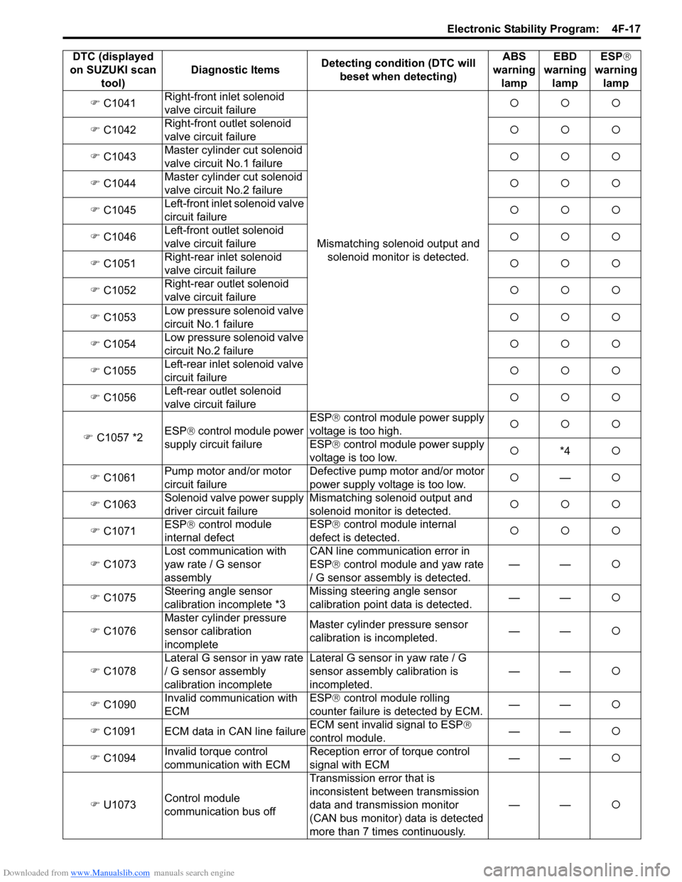
Downloaded from www.Manualslib.com manuals search engine Electronic Stability Program: 4F-17
�) C1041 Right-front inlet solenoid
valve circuit failure
Mismatching solenoid output and solenoid monitor is detected. �{�{�{
�) C1042 Right-front outlet solenoid
valve circuit failure �{�{�{
�) C1043 Master cylinder cut solenoid
valve circuit No.1 failure �{�{�{
�) C1044 Master cylinder cut solenoid
valve circuit No.2 failure �{�{�{
�) C1045 Left-front inlet solenoid valve
circuit failure �{�{�{
�) C1046 Left-front outlet solenoid
valve circuit failure �{�{�{
�) C1051 Right-rear inlet solenoid
valve circuit failure �{�{�{
�) C1052 Right-rear outlet solenoid
valve circuit failure �{�{�{
�) C1053 Low pressure solenoid valve
circuit No.1 failure �{�{�{
�) C1054 Low pressure solenoid valve
circuit No.2 failure �{�{�{
�) C1055 Left-rear inlet solenoid valve
circuit failure �{�{�{
�) C1056 Left-rear outlet solenoid
valve circuit failure �{�{�{
�) C1057 *2 ESP
® control module power
supply circuit failure ESP®
control module power supply
voltage is too high. �{�{�{
ESP® control module power supply
voltage is too low. �{
*4 �{
�) C1061 Pump motor and/or motor
circuit failure Defective pump motor and/or motor
power supply voltage is too low.
�{
— �{
�) C1063 Solenoid valve
power supply
driver circuit failure Mismatching solenoid output and
solenoid monitor is detected.
�{�{�{
�) C1071 ESP
® con
trol module
internal defect ESP®
control module internal
defect is detected. �{�{�{
�) C1073 Lost communication with
yaw rate / G sensor
assembly CAN line communication error in
ESP®
control module and yaw rate
/ G sensor assembly is detected. ——
�{
�) C1075 Steering angle sensor
calibration incomplete *3 Missing steering angle sensor
calibration point data is detected.
——
�{
�) C1076 Master cylinder pressure
sensor calibration
incomplete Master cylinder pressure sensor
calibration is incompleted.
——
�{
�) C1078 Lateral G sensor in yaw rate
/ G sensor assembly
calibration incomplete Lateral G sensor in yaw rate / G
sensor assembly calibration is
incompleted.
——
�{
�) C1090 Invalid communication with
ECM ESP®
control module rolling
counter failure is detected by ECM. ——
�{
�) C1091 ECM data in CAN line failure ECM sent invalid signal to ESP
®
control module. ——
�{
�) C1094 Invalid torque control
communication with ECM Reception error of torque control
signal with ECM
——
�{
�) U1073 Control module
communication bus off Transmission error that is
inconsistent between transmission
data and transmission monitor
(CAN bus monitor) data is detected
more than 7 times continuously.
——
�{
DTC (displayed
on SUZUKI scan tool) Diagnostic Items
Detecting condition (DTC will
beset when detecting) ABS
warning lamp EBD
warning lamp ESP
®
warning lamp
Page 592 of 1496

Downloaded from www.Manualslib.com manuals search engine 4F-18 Electronic Stability Program:
NOTE
•“�{” in ABS warning lamp, EBD warning lamp and ESP ® warning lamp column of the above table
means warning lamp is li t when DTC is detected.
• *1: If two or more wheel speed sensor are defective, ABS warning lamp, EBD warning lamp and ESP ® warning lamp are lit and all the control functions are deactivated. If one wheel speed sensor is
defective, ABS warning lamp and ESP ® warning lamp are lit and ABS and TCS / stability control are
deactivated.
• *2: SLIP indicator lamp and ESP ® OFF lamp turn ON when power supply circuit voltage is low.
• *3: SLIP indicator lamp flashes continuously at Intervals of 1 Hz.
• *4: EBD warning lamp is lit when power supply circuit voltage is too low.
DTC ClearanceS7RS0B4604006
WARNING!
When performing a driving test, select a safe place where there is neither any traffic nor any traffic
accident possibility and be very careful during testing to avoid occurrence of an accident.
1) Connect SUZUKI scan tool to data link connector in the same manner as when making this connection for DTC
check.
2) Turn ignition switch to ON position.
3) Erase DTC according to instructions displayed on scan t ool. Refer to scan tool operator’s manual for further
derails.
4) After completing the clearance, tu rn ignition switch OFF and disconnec t scan tool from data link connector.
5) Perform “Driving Test” (Step 2 of “E lectronic Stability Program System Check” ) and “DTC Check” and confirm that
NO DTC is displayed on scan tool. �)
U1100 Lost communication with
ECM (reception error) ECM message data is missing from
CAN communication.
——
�{
�) U1126 Lost communication with
steering angle sensor
(reception error) Steering angle sensor message
data is missing from CAN
communication.
——
�{
�) U1140 Lost communication with
BCM (reception error) BCM message data is missing from
CAN communication.
——
�{
DTC (displayed
on SUZUKI scan tool) Diagnostic Items
Detecting condition (DTC will
beset when detecting) ABS
warning lamp EBD
warning lamp ESP
®
warning lamp