2008 SUZUKI SWIFT Air Flow Control Actuator
[x] Cancel search: Air Flow Control ActuatorPage 22 of 1496
Downloaded from www.Manualslib.com manuals search engine 0A-1 General Information:
General Information
General Information
General Description
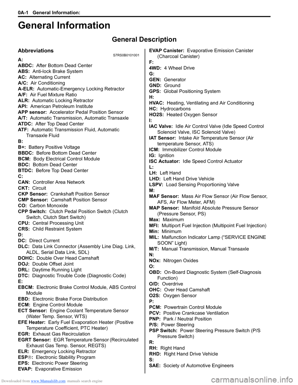
AbbreviationsS7RS0B0101001
A:
ABDC: After Bottom Dead Center
ABS: Anti-lock Brake System
AC: Alternating Current
A/C: Air Conditioning
A-ELR: Automatic-Emergency Locking Retractor
A/F: Air Fuel Mixture Ratio
ALR: Automatic Locking Retractor
API: American Petroleum Institute
APP sensor: Accelerator Pedal Position Sensor
A/T: Automatic Transmission , Automatic Transaxle
AT D C : After Top Dead Center
ATF: Automatic Transmission Fluid, Automatic
Transaxle Fluid
B:
B+: Battery Positive Voltage
BBDC: Before Bottom Dead Center
BCM: Body Electrical Control Module
BDC: Bottom Dead Center
BTDC: Before Top Dead Center
C:
CAN: Controller Area Network
CKT: Circuit
CKP Sensor: Crankshaft Position Sensor
CMP Sensor: Camshaft Position Sensor
CO: Carbon Monoxide
CPP Switch: Clutch Pedal Position Switch (Clutch
Switch, Clutch Start Switch)
CPU: Central Processing Unit
CRS: Child Restraint System
D:
DC: Direct Current
DLC: Data Link Connector (Assembly Line Diag. Link,
ALDL, Serial Data Link, SDL)
DOHC: Double Over Head Camshaft
DOJ: Double Offset Joint
DRL: Daytime Running Light
DTC: Diagnostic Trouble Code (Diagnostic Code)
E:
EBCM: Electronic Brake Cont rol Module, ABS Control
Module
EBD: Electronic Brake Force Distribution
ECM: Engine Control Module
ECT Sensor: Engine Coolant Temperature Sensor (Water Temp. Sensor, WTS)
EFE Heater: Early Fuel Evaporation Heater (Positive
Temperature Coefficient, PTC Heater)
EGR: Exhaust Gas Recirculation
EGRT Sensor: EGR Temperature Sensor (Recirculated
Exhaust Gas Temp. Sensor, REGTS)
ELR: Emergency Locking Retractor
ESP ®: Electronic Stability Program
EPS: Electronic Power Steering
EVAP: Evaporative Emission EVAP Canister:
Evaporative Emission Canister
(Charcoal Canister)
F:
4WD: 4 Wheel
Drive
G:
GEN: Generator
GND: Ground
GPS: Global Positioning System
H:
HVAC: Heating, Ventilating and Air Conditioning
HC: Hydrocarbons
HO2S: Heated Oxygen Sensor
I:
IAC Valve: Idle Air Control Valve (Idle Speed Control
Solenoid Valve, ISC Solenoid Valve)
IAT Sensor: Intake Air Temperature Sensor (Air
temperature Sensor, ATS)
ICM: Immobilizer Control Module
IG: Ignition
ISC Actuator: Idle Speed Control Actuator
L:
LH: Left Hand
LHD: Left Hand Drive Vehicle
LSPV: Load Sensing Proportioning Valve
M:
MAF Sensor: Mass Air Flow Sensor (Air Flow Sensor, AFS, Air Flow Meter, AFM)
MAP Sensor: Manifold Absolute Pressure Sensor
(Pressure Sensor, PS)
Max: Maximum
MFI: Multiport Fuel Injection (Mu ltipoint Fuel Injection)
Min: Minimum
MIL: Malfunction Indicator Lamp (“SERVICE ENGINE
SOON” Light)
M/T: Manual Transmission, Manual Transaxle
N:
NOx: Nitrogen Oxides
O:
OBD: On-Board Diagnostic System (Self-Diagnosis
Function)
O/D: Overdrive
OHC: Over Head Camshaft
O2S: Oxygen Sensor
P:
PCM: Powertrain Control Module
PCV: Positive Crankcase Ventilation
PNP: Park / Neutral Position
P/S: Power Steering
PSP Switch: Power Steering Pressure Switch (P/S
Pressure Switch)
R:
RH: Right Hand
RHD: Right Hand Drive Vehicle
S:
SAE: Society of Automotive Engineers
Page 45 of 1496
Downloaded from www.Manualslib.com manuals search engine Table of Contents 1- i
1
Section 1
CONTENTS
Engine
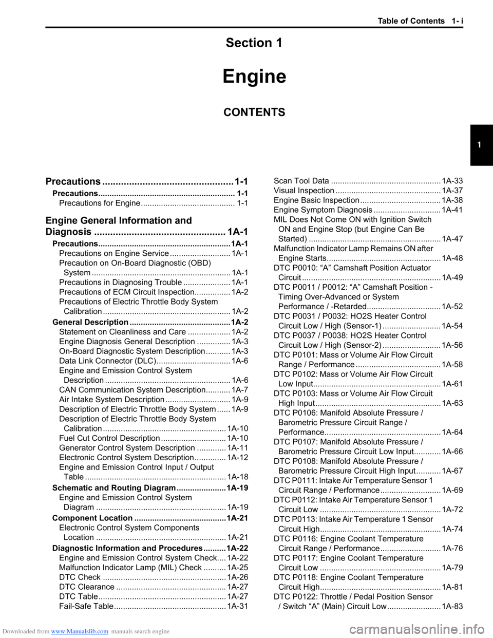
Precautions ................................................. 1-1
Precautions............................................................. 1-1
Precautions for Engine .......................................... 1-1
Engine General Information and
Diagnosis ............. .................................... 1A-1
Precautions........................................................... 1A-1
Precautions on Engine Service ........................... 1A-1
Precaution on On-Board Diagnostic (OBD) System .............................................................. 1A-1
Precautions in Diagnosing Trouble ..................... 1A-1
Precautions of ECM Circuit Inspection................ 1A-2
Precautions of Electric Throttle Body System
Calibration ......................................................... 1A-2
General Description ............................................. 1A-2 Statement on Cleanliness and Care ................... 1A-2
Engine Diagnosis General Description ............... 1A-3
On-Board Diagnostic System Description ........... 1A-3
Data Link Connector (DLC) ................................. 1A-6
Engine and Emission Control System Description ........................................................ 1A-6
CAN Communication System Description........... 1A-7
Air Intake System Description ............................. 1A-9
Description of Electric Throttle Body System ...... 1A-9
Description of Electric Throttle Body System Calibration ....................................................... 1A-10
Fuel Cut Control Description ............................. 1A-10
Generator Control System Description ............. 1A-11
Electronic Control System Description .............. 1A-12
Engine and Emission Control Input / Output Table ............................................................... 1A-18
Schematic and Routing Diagram ...................... 1A-19 Engine and Emission Control System Diagram .......................................................... 1A-19
Component Locatio n ......................................... 1A-21
Electronic Control System Components Location .......................................................... 1A-21
Diagnostic Information and Procedures .......... 1A-22 Engine and Emission Control System Check.... 1A-22
Malfunction Indicator Lamp (MIL) Check .......... 1A-25
DTC Check ....................................................... 1A-26
DTC Clearance ................................................. 1A-27
DTC Table ......................................................... 1A-27
Fail-Safe Table ................ .................................. 1A-31 Scan Tool Data ................................................. 1A-33
Visual Inspection ............................................... 1A-37
Engine Basic Inspection .................................... 1A-38
Engine Symptom Diagnosis .............................. 1A-41
MIL Does Not Come ON with Ignition Switch
ON and Engine Stop (but Engine Can Be
Started) ........................................................... 1A-47
Malfunction Indicator Lamp Remains ON after Engine Starts................................................... 1A-48
DTC P0010: “A” Camshaft Position Actuator Circuit .............................................................. 1A-49
DTC P0011 / P0012: “A” Camshaft Position - Timing Over-Advanced or System
Performance / -Retarded................................. 1A-52
DTC P0031 / P0032: HO2S Heater Control Circuit Low / High (Sensor-1) .......................... 1A-54
DTC P0037 / P0038: HO2S Heater Control Circuit Low / High (Sensor-2) .......................... 1A-56
DTC P0101: Mass or Volume Air Flow Circuit Range / Performance ...................................... 1A-58
DTC P0102: Mass or Volume Air Flow Circuit Low Input......................................................... 1A-61
DTC P0103: Mass or Volume Air Flow Circuit High Input ........................................................ 1A-63
DTC P0106: Manifold Absolute Pressure /
Barometric Pressure Circuit Range /
Performance.................................................... 1A-64
DTC P0107: Manifold Absolute Pressure /
Barometric Pressure Circ uit Low Input............ 1A-66
DTC P0108: Manifold Absolute Pressure /
Barometric Pressure Circ uit High Input ........... 1A-67
DTC P0111: Intake Air Temperature Sensor 1 Circuit Range / Performance ........................... 1A-69
DTC P0112: Intake Air Temperature Sensor 1 Circuit Low ...................................................... 1A-72
DTC P0113: Intake Air Temperature 1 Sensor Circuit High...................................................... 1A-74
DTC P0116: Engine Coolant Temperature Circuit Range / Performance ........................... 1A-76
DTC P0117: Engine Coolant Temperature Circuit Low ...................................................... 1A-79
DTC P0118: Engine Coolant Temperature Circuit High...................................................... 1A-81
DTC P0122: Throttle / Pedal Position Sensor / Switch “A” (Main) Circuit Low ........................ 1A-83
Page 46 of 1496
Downloaded from www.Manualslib.com manuals search engine 1-ii Table of Contents
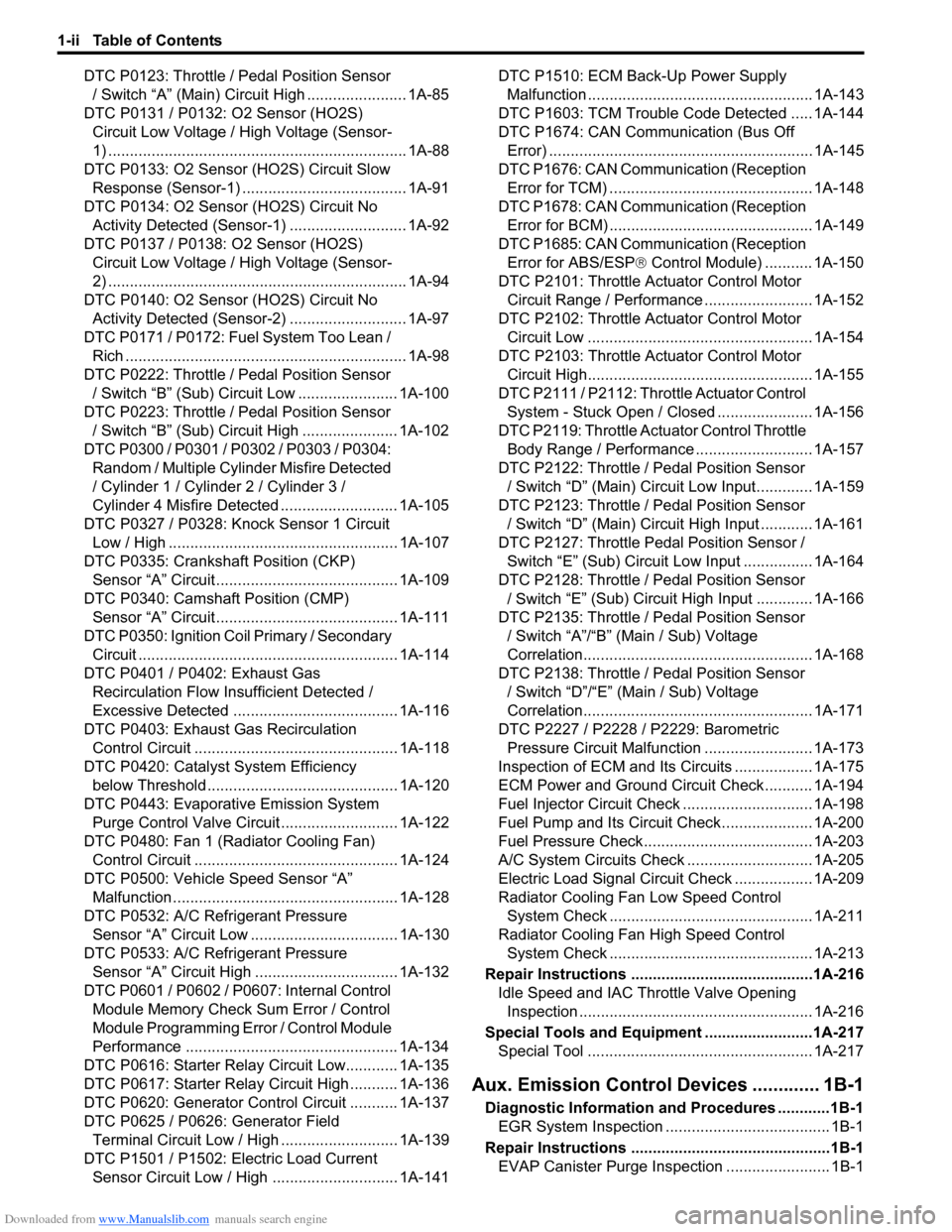
DTC P0123: Throttle / Pedal Position Sensor / Switch “A” (Main) Circuit High ....................... 1A-85
DTC P0131 / P0132: O2 Sensor (HO2S) Circuit Low Voltage / High Voltage (Sensor-
1) ..................................................................... 1A-88
DTC P0133: O2 Sensor (HO2S) Circuit Slow
Response (Sensor- 1) ...................................... 1A-91
DTC P0134: O2 Sensor (HO2S) Circuit No Activity Detected (Sensor -1) ........................... 1A-92
DTC P0137 / P0138: O2 Sensor (HO2S) Circuit Low Voltage / High Voltage (Sensor-
2) ..................................................................... 1A-94
DTC P0140: O2 Sensor (HO2S) Circuit No Activity Detected (Sensor -2) ........................... 1A-97
DTC P0171 / P0172: Fuel System Too Lean / Rich ................................................................. 1A-98
DTC P0222: Throttle / Pedal Position Sensor / Switch “B” (Sub) Circuit Low ....................... 1A-100
DTC P0223: Throttle / Pedal Position Sensor / Switch “B” (Sub) Circuit High ...................... 1A-102
DTC P0300 / P0301 / P0302 / P0303 / P0304: Random / Multiple Cylin der Misfire Detected
/ Cylinder 1 / Cylinder 2 / Cylinder 3 /
Cylinder 4 Misfire Detected ........................... 1A-105
DTC P0327 / P0328: Knoc k Sensor 1 Circuit
Low / High ..................................................... 1A-107
DTC P0335: Crankshaft Position (CKP) Sensor “A” Circuit .......................................... 1A-109
DTC P0340: Camshaft Position (CMP) Sensor “A” Circuit .......................................... 1A-111
DTC P0350: Ignition Coil Primary / Secondary Circuit ............................................................ 1A-114
DTC P0401 / P0402: Exhaust Gas Recirculation Flow Insufficient Detected /
Excessive Detected ...................................... 1A-116
DTC P0403: Exhaust Gas Recirculation Control Circuit ................... ............................ 1A-118
DTC P0420: Catalyst System Efficiency
below Threshold ................ ............................ 1A-120
DTC P0443: Evaporativ e Emission System
Purge Control Valve Circuit ........................... 1A-122
DTC P0480: Fan 1 (Radiator Cooling Fan) Control Circuit ................... ............................ 1A-124
DTC P0500: Vehicle Speed Sensor “A” Malfunction .................................................... 1A-128
DTC P0532: A/C Refrigerant Pressure Sensor “A” Circuit Low ... ............................... 1A-130
DTC P0533: A/C Refrigerant Pressure Sensor “A” Circuit High ................................. 1A-132
DTC P0601 / P0602 / P0607: Internal Control Module Memory Check Sum Error / Control
Module Programming Error / Control Module
Performance ................................................. 1A-134
DTC P0616: Starter Relay Circuit Low............ 1A-135
DTC P0617: Starter Relay Circuit High ........... 1A-136
DTC P0620: Generator Control Circuit ........... 1A-137
DTC P0625 / P0626: Generator Field Terminal Circuit Low / High . .......................... 1A-139
DTC P1501 / P1502: Electric Load Current Sensor Circuit Low / High . ............................ 1A-141 DTC P1510: ECM Back-Up Power Supply
Malfunction .................................................... 1A-143
DTC P1603: TCM Trouble Code Detected ..... 1A-144
DTC P1674: CAN Communication (Bus Off Error) ............................................................. 1A-145
DTC P1676: CAN Communication (Reception Error for TCM) ............................................... 1A-148
DTC P1678: CAN Communication (Reception Error for BCM) ............................................... 1A-149
DTC P1685: CAN Communication (Reception Error for ABS/ESP ® Control Module) ........... 1A-150
DTC P2101: Throttle Actuator Control Motor Circuit Range / Performance ......................... 1A-152
DTC P2102: Throttle Actuator Control Motor Circuit Low .................................................... 1A-154
DTC P2103: Throttle Actuator Control Motor Circuit High.................................................... 1A-155
DTC P2111 / P2112: Throttle Actuator Control System - Stuck Open / Closed ...................... 1A-156
DTC P2119: Throttle Actu ator Control Throttle
Body Range / Performance ........................... 1A-157
DTC P2122: Throttle / Pedal Position Sensor / Switch “D” (Main) Circuit Low Input............. 1A-159
DTC P2123: Throttle / Pedal Position Sensor / Switch “D” (Main) Circuit High Input ............ 1A-161
DTC P2127: Throttle Pedal Position Sensor / Switch “E” (Sub) Circuit Low Input ................ 1A-164
DTC P2128: Throttle / Pedal Position Sensor
/ Switc
h “E” (Sub) Circuit High Input ............. 1A-166
DTC P2135: Throttle / Pedal Position Sensor / Switch “A”/“B” (Main / Sub) Voltage
Correlation..................................................... 1A-168
DTC P2138: Throttle / Pedal Position Sensor / Switch “D”/“E” (Main / Sub) Voltage
Correlation..................................................... 1A-171
DTC P2227 / P2228 / P2229: Barometric Pressure Circuit Malfunction ......................... 1A-173
Inspection of ECM and Its Circuits .................. 1A-175
ECM Power and Ground Circuit Check........... 1A-194
Fuel Injector Circuit Check .............................. 1A-198
Fuel Pump and Its Circuit Check..................... 1A-200
Fuel Pressure Check....................................... 1A-203
A/C System Circuits Check ............................. 1A-205
Electric Load Signal Circuit Check .................. 1A-209
Radiator Cooling Fan Low Speed Control System Check ............................................... 1A-211
Radiator Cooling Fan High Speed Control System Check ............................................... 1A-213
Repair Instructions ......... .................................1A-216
Idle Speed and IAC Throttle Valve Opening Inspection ...................................................... 1A-216
Special Tools and Equipmen t .........................1A-217
Special Tool .................................................... 1A-217
Aux. Emission Control Devices ............. 1B-1
Diagnostic Information and Procedures ............1B-1
EGR System Inspection ...................................... 1B-1
Repair Instructions ............ ..................................1B-1
EVAP Canister Purge Inspec tion ........................ 1B-1
Page 63 of 1496
Downloaded from www.Manualslib.com manuals search engine Engine General Information and Diagnosis: 1A-13
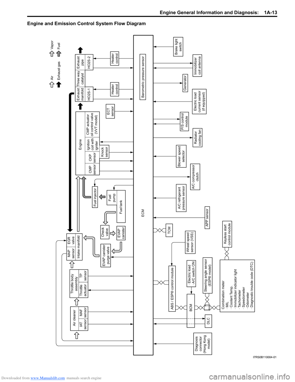
Engine and Emission Control System Flow Diagram
Intake manifold
Exhaust gas AirFuel
Va p o r
EVAP canister purge valve
ECM
Barometric pressure sensor
A/C compressor clutch
Generator
Immobilizer
coil antenna
P/S controlmodule
Brake light switch
Air cleaner
IAT
sensor MAF
sensor
A/C refrigerant
pressure sensor
TP
sensor
Throttle body
assembly
Throttle
actuator
Wheel speed
sensor (VSS)
Steering angle sensor (ESP® model)
ABS / ESP® control module
Blower speed
selector
MAP
sensor EGR
valve
Check valve
EVAP
canisterTCM
Exhaust
manifold Exhaust
pipe
Fuel injector
ECT
sensor
Heater
control
HO2S-1 HO2S-2
Engine
CMP
sensor CKP
sensor
Knock
sensor Ignition
coil with
igniter
Fuel tank
Fuel
pump CMP actuator
oil control valve (VVT model) Three way
catalyst
Heater
control
Radiator
cooling fan
Combination meter
· MIL
· Coolant Temp.
· Immobilizer indicator light
· Tachometer
· Speedometer
· Odometer
· Diagnostic trouble code (DTC)
Keyless start
control module
DLC
· Electric load
· A/C switch ON
BCM
Diagnosis
connector
(Hong Kong model) Electric load
current sensor (if equipped)
APP sensor
I7RS0B110004-01
Page 81 of 1496
Downloaded from www.Manualslib.com manuals search engine Engine General Information and Diagnosis: 1A-31
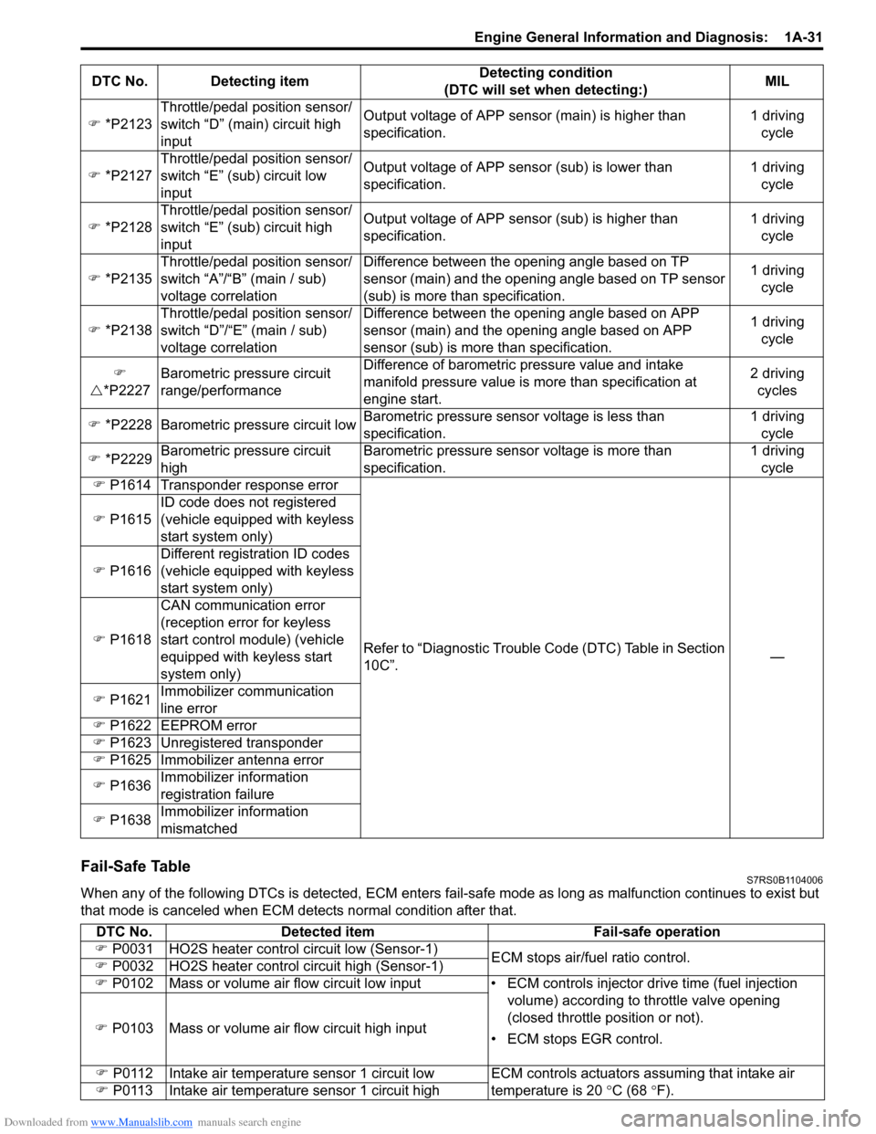
Fail-Safe TableS7RS0B1104006
When any of the following DTCs is detected, ECM enters fail-safe mode as long as malfunction continues to exist but
that mode is canceled when ECM de tects normal condition after that.
)
*P2123 Throttle/pedal position sensor/
switch “D” (main) circuit high
input Output voltage of APP sensor (main) is higher than
specification.
1 driving
cycle
) *P2127 Throttle/pedal position sensor/
switch “E” (sub) circuit low
input Output voltage of APP sens
or (sub) is lower than
specification. 1 driving
cycle
) *P2128 Throttle/pedal position sensor/
switch “E” (sub) circuit high
input Output voltage of APP sensor (sub) is higher than
specification.
1 driving
cycle
) *P2135 Throttle/pedal position sensor/
switch “A”/“B” (main / sub)
voltage correlation Difference between the opening angle based on TP
sensor (main) and the opening angle based on TP sensor
(sub) is more than specification.
1 driving
cycle
) *P2138 Throttle/pedal position sensor/
switch “D”/“E” (main / sub)
voltage correlation Difference between the opening angle based on APP
sensor (main) and the opening angle based on APP
sensor (sub) is more
than specification. 1 driving
cycle
)
U *P2227 Barometric pressure circuit
range/performance Difference of barometric pressure value and intake
manifold pressure value is
more than specification at
engine start. 2 driving
cycles
) *P2228 Barometric pressure circuit low Barometric pressure sens
or voltage is less than
specification. 1 driving
cycle
) *P2229 Barometric pressure circuit
high Barometric pressure sensor voltage is more than
specification. 1 driving
cycle
) P1614 Transponder response error
Refer to “Diagnostic Trouble Code (DTC) Table in Section
10C”. —
) P1615 ID code does not registered
(vehicle equipped with keyless
start system only)
) P1616 Different registration ID codes
(vehicle equipped with keyless
start system only)
) P1618 CAN communication error
(reception error for keyless
start control module) (vehicle
equipped with keyless start
system only)
) P1621 Immobilizer communication
line error
) P1622
EEPROM error
) P1623 Unregistered transponder
) P1625 Immobilizer antenna error
) P1636 Immobilizer information
registration failure
) P1638 Immobilizer information
mismatched
DTC No. Detecting item
Detecting condition
(DTC will set when detecting:) MIL
DTC No.
Detected item Fail-safe operation
) P0031 HO2S heater control circuit low (Sensor-1)
ECM stops air/fuel ratio control.
) P0032 HO2S heater control circuit high (Sensor-1)
) P0102 Mass or volume air flow circuit low input • ECM controls injector drive time (fuel injection
volume) according to throttle valve opening
(closed throttle position or not).
• ECM stops EGR control.
)
P0103 Mass or volume air flow circuit high input
) P0112 Intake air temperature sensor 1 circuit low ECM controls actuators assuming that intake air
temperature is 20 °C (68 ° F).
) P0113 Intake air temperature sensor 1 circuit high
Page 99 of 1496
Downloaded from www.Manualslib.com manuals search engine Engine General Information and Diagnosis: 1A-49
Troubleshooting
NOTE
When measuring circuit voltage, resistance and/or pulse signal at ECM connector, connect the special
tool to ECM and/or the ECM connectors referri ng to “Inspection of ECM and Its Circuits”.
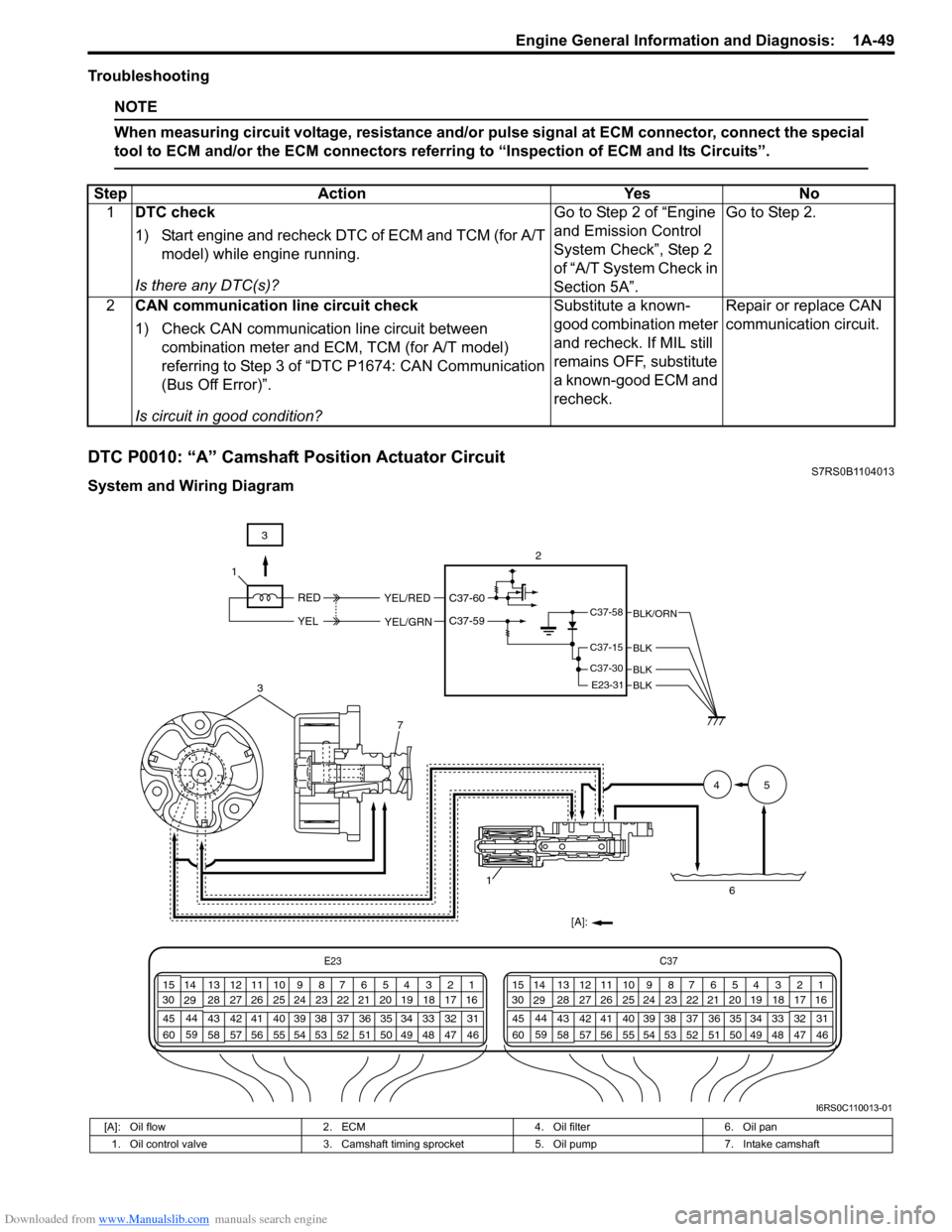
DTC P0010: “A” Camshaft Position Actuator CircuitS7RS0B1104013
System and Wiring DiagramStep Action Yes No
1 DTC check
1) Start engine and recheck DTC of ECM and TCM (for A/T
model) while engine running.
Is there any DTC(s)? Go to Step 2 of “Engine
and Emission Control
System Check”, Step 2
of “A/T System Check in
Section 5A”.Go to Step 2.
2 CAN communication line circuit check
1) Check CAN communication line circuit between
combination meter and ECM, TCM (for A/T model)
referring to Step 3 of “DTC P1674: CAN Communication
(Bus Off Error)”.
Is circuit in good condition? Substitute a known-
good combination meter
and recheck. If MIL still
remains OFF, substitute
a known-good ECM and
recheck.
Repair or replace CAN
communication circuit.
3
7
1[A]: 45
6
C37-58
C37-15
C37-30
E23-31BLK
BLK
BLK/ORN
RED
YEL
YEL/RED
YEL/GRN
C37-60
C37-59
3 2
1
E23 C37
34
1819
567
1011
17
20
47 46
495051
2122
52 16
25 9
24
14
29
55
57 54 53
59
60 58 2
262728
15
30
56 4832 31
34353637
40
42 39 38
44
45 43 41 331
1213
238
34
1819
567
1011
17
20
47 46
495051
2122
52 16
25 9
24
14
29
55
57 54 53
59
60 58 2
262728
15
30
56 4832 31
34353637
40
42 39 38
44
45 43 41 331
1213
238
BLK
I6RS0C110013-01
[A]: Oil flow
2. ECM4. Oil filter6. Oil pan
1. Oil control valve 3. Camshaft timing sprocket5. Oil pump7. Intake camshaft
Page 890 of 1496

Downloaded from www.Manualslib.com manuals search engine 6C-8 Power Assisted Steering System:
Step 2: DTC Check, Record and Clearance
First, check DTC, referring to “DTC Check”. If DTC is
indicated, print it or write them down and then clear them
by referring to “DTC Clearance”. DTC indicates
malfunction that occurred in the system but does not
indicate whether it exists now or it occurred in the past
and the normal condition has been restored now. To
check which case applies, check the symptom in
question according to Step 5 and recheck DTC
according to Step 6 and 7.
Attempt to diagnose a trouble based on DTC in this step
only or failure to clear the DTC in this step will lead to
incorrect diagnosis, trouble diagnosis of a normal circuit
or difficulty in troubleshooting.
Step 3 and 4: Visual Inspection
As a preliminary step, be sure to perform visual check of
the items that support proper function of the P/S system
referring to “Visual Inspection”.
Step 5: Trouble Symptom Confirmation
Based on information obtained in “Step 1: Customer
Complaint Analysis: ” and “S tep 2: DTC Check, Record
and Clearance: ”, confirm trouble symptoms. Also,
reconfirm trouble symptom by performing test drive and
turning steering wheel fully to right and left at stopped
vehicle.
Step 6 and 7: Rechecking and Record of DTC
Refer to “DTC Check” for checking procedure.
Step 8: Steering Symptom Diagnosis and P/S
System Symptom Diagnosis
Perform basic steering system check according to
“Steering Symptom Diagnosis in Section 6A” first. When
the end of the flow has been reached, check the parts of
the system suspected as a possible cause referring to
“P/S System Symptom Diagnosis” and based on
symptoms appearing on the vehicle (symptoms obtained
through steps of customer complaint analysis, trouble
symptom confirmation and/or basic P/S system check)
and repair or replace faulty parts, if any.
Step 9: Troubleshooting for DTC (See each DTC
Diag. Flow)
Based on the DTC indicated in Step 6 or 7 and referring
to the applicable DTC diag. flow, locate the cause of the
trouble, namely in a sensor, switch, wire harness,
connector, actuator, P/S control module or other part and
repair or replace faulty parts.
Step 10: Intermittent Problems Check
Check parts where an intermittent trouble is easy to
occur (e.g., wire harness, connector, etc.), referring to
“Intermittent and Poor Connection Inspection in Section
00” and related circuit of DTC recorded in Step 2. Step 11: Final Confirmation Test
Confirm that the problem symptom has gone and the P/
S system is free from any abnormal conditions. If what
has been repaired is related to the DTC, clear the DTC
once, perform DTC confirmation procedure and confirm
that no DTC is indicated.
“EPS” Warning Light CheckS7RS0B6304002
1) Turn ignition switch to ON position (without engine
running) and chec k if the “EPS” warning light (1)
lights up. If the light dose not light up, go to ““EPS”
Warning Light Does Not Come ON with Ignition
Switch Turned ON before Engine Starts” of the
diagnostic flows.
2) Start engine and check if the “EPS” warning light turns OFF. If light remains ON and no DTC is stored
in P/S control module, go to ““EPS” Warning Light
Remains ON Steady after Engine Starts” for
troubleshooting.
DTC CheckS7RS0B6304003
1) Turn ignition switch to OFF position.
2) Connect SUZUKI scan tool to data link connector (DLC) (1) located on underside of instrument panel
at driver’s seat side.
Special tool
(A): SUZUKI scan tool
1
I6RS0C630002-01
(A)
1
I4RS0B450003-01
Page 934 of 1496
Downloaded from www.Manualslib.com manuals search engine 7-ii Table of Contents
Recommended Service Material ....................... 7B-33
Special Tool ...................................................... 7B-33
Automatic Type .................... .................................7B-34
Precautions.........................................................7B-34 A/C System Caution .......................................... 7B-34
Precautions in Diagnosing Trouble ................... 7B-34
Precautions on Servicing A/C System .............. 7B-34
General Description .......... .................................7B-34
Auto A/C System Descript ion ............................ 7B-34
HVAC Control Module Operation Description ... 7B-36
Refrigerant Type Identifica tion .......................... 7B-36
Sub-Cool A/C System Description .................... 7B-36
A/C Operation Description ................................ 7B-36
On-Board Diagnostic System Description ......... 7B-37
Schematic and Routing Diagram ......................7B-37 Major Components of A/C System .................... 7B-37
A/C System Wiring Diagra m ............................. 7B-38
Diagnostic Information and Procedures ..........7B-39 A/C System Symptom Diagnosis ...................... 7B-39
Abnormal Noise Sympto m Diagnosis of A/C
System ............................................................ 7B-42
DTC Check........................................................ 7B-42
DTC Clearance ................................................. 7B-43
DTC Table ......................................................... 7B-44
Fail-Safe Table ................. ................................. 7B-45
Scan Tool Data ................................................. 7B-46
Air Conditioning System Check......................... 7B-47
Visual Inspection ............................................... 7B-49
DTC B1502: Inside Air Temperature Sensor and/or Its Circuit Malfunction .......................... 7B-49
DTC B1503: A/C Evaporator Air Temperature Sensor and/or Its Circuit Malfunction .............. 7B-50
DTC B1504: Sunload Sensor and/or Its Circuit Malfunction ......... ................................. 7B-52
DTC B1511: Temperature Control Actuator (Position Sensor) and/or Its Circuit
Malfunction ...................................................... 7B-53
DTC B1512: Air flow Control Actuator (Position Sensor) and/or Its Circuit
Malfunction ...................................................... 7B-55
DTC B1513: Temperature Control Actuator and/or Its Circuit Malfunction .......................... 7B-57
DTC B1514: Air Flow Co ntrol Actuator and/or
Its Circuit Malfunction ...................................... 7B-60
DTC B1541: HVAC Control Module Back-Up Power Supply Malfunction .............................. 7B-62
DTC B1546: A/C Refrigerant Pressure Malfunction ...................................................... 7B-63
DTC B1551: Serial Communication Circuit Malfunction ...................................................... 7B-63
DTC B1552: Serial Communication Signal Malfunction ...................................................... 7B-64
DTC B1553: CAN Communication Signal Malfunction ...................................................... 7B-65
DTC B1557: Vehicle Speed Sensor Signal Malfunction ...................................................... 7B-65
DTC B1561: Engine Coolant Temperature Sensor Signal Malfunctio n .............................. 7B-66 DTC B1562: Outside Air Temperature Sensor
Signal Malfunction ........................................... 7B-66
DTC B1563: A/C Refr igerant Pressure
Sensor Signal Malfunction .............................. 7B-66
Inspection of HVAC Control Module and Its Circuit .............................................................. 7B-67
A/C System Performance Inspection ................ 7B-70
A/C System Inspection at ECM ......................... 7B-70
Repair Instructions ............ ................................7B-71
Operation Procedure for Refrigerant Charge .... 7B-71
HVAC Unit Components ................................... 7B-72
HVAC Unit Removal and In stallation ................ 7B-73
Temperature Control Actuator Removal and Installation ....................................................... 7B-73
Temperature Control Actuat or Inspection ......... 7B-73
Air Flow Control Actuator Removal and Installation ....................................................... 7B-74
Air Flow Control Actuator Inspection ................. 7B-74
Air Intake Control Actuator Removal and Installation ....................................................... 7B-75
Air Intake Control Actuator Inspection............... 7B-75
Actuator Linkage Inspection .............................. 7B-76
Blower Motor Controller Removal and Installation ....................................................... 7B-76
Blower Motor Controller Inspection ................... 7B-76
HVAC Control Module Removal and Installation ....................................................... 7B-77
Sunload Sensor Removal and Installation ........ 7B-77
Sunload Sensor Inspection ............................... 7B-77
Outside Air Temperature Sensor Removal and Installation ................................................ 7B-77
Outside Air Temperature Sensor Inspection ..... 7B-77
Inside Air Temperature Sensor Removal and Installation ....................................................... 7B-78
Inside Air Temperature Sens or Inspection ........ 7B-78
Condenser Assembly On-Vehicle Inspection .... 7B-78
Condenser Assembly Removal and Installation ....................................................... 7B-78
Receiver/Dryer Removal and Installation .......... 7B-78
Evaporator Inspection ....................................... 7B-78
Evaporator Temperature Sensor Removal and Installation ................................................ 7B-78
Evaporator Temperature Se nsor Inspection ..... 7B-78
Expansion Valve Removal an d Installation ....... 7B-78
Expansion Valve Inspection .............................. 7B-78
A/C Refrigerant Pressure Sensor and Its Circuit Inspection............................................. 7B-78
A/C Refrigerant Pressu re Sensor Removal
and Installation ................................................ 7B-78
Compressor Relay Inspection .
.......................... 7B-78
Compressor Drive Belt Inspection and Adjustment ...................................................... 7B-78
Compressor Drive Belt Removal and Installation ....................................................... 7B-79
Compressor Assembly Removal and Installation ....................................................... 7B-79
Compressor Assembly Components................. 7B-79
Magnet Clutch Removal and Installation........... 7B-79
Magnet Clutch Inspection.................................. 7B-79
Relief Valve Inspection...................................... 7B-79