Page 864 of 1496

Downloaded from www.Manualslib.com manuals search engine 5C-12 Clutch:
2) Install release shaft.
3) Apply grease to No.2 bush (1) inside and press-fit it using the same special tool as in removal.
“A”: Grease 99000–25011 (SUZUKI Super
Grease A)
Special tool
(A): 09922–46010
4) Coat grease to release shaft seal (2) lip and then install it till it is flush wit h case surface. Use special
tool for this installation a nd face seal lip downward
(inside).
“A”: Grease 99000–25011 (SUZUKI Super
Grease A)
Special tool
(B): 09925–98221
5) Caulk seal at A using caulking tool and hammer. 6) Apply grease to release bearing inside and release
shaft (2), then set release bearing (1).
“A”: Grease 99000–25011 (SUZUKI Super
Grease A)
7) Apply small amount of grease to input shaft (3) spline (0.3 g (0.01 oz)) and front end (0.15 g (0.005
oz)) as well.
“B”: Grease 99000–25210 (SUZUKI Super
Grease I)
8) Set release arm (1) to release shaft (2) aligning punch mark (4) of release arm and punch mark (3) of
release shaft, then tighten bolt to specified torque.
Tightening torque
Release lever bolt (a): 23 N·m (2.3 kgf-m, 17.0 lb-
ft)
I3RM0A530017-01
I4RS0A530021-01
(a)3
241
I4RS0A530022-01
Page 865 of 1496

Downloaded from www.Manualslib.com manuals search engine Clutch: 5C-13
Clutch Release System InspectionS7RS0B5306017
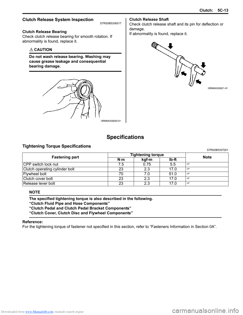
Clutch Release Bearing
Check clutch release bearing for smooth rotation. If
abnormality is found, replace it.
CAUTION!
Do not wash release bearing. Washing may
cause grease leakage and consequential
bearing damage.
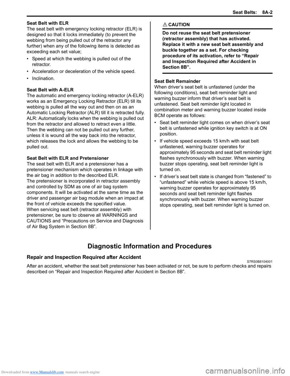
Clutch Release Shaft
Check clutch release shaft and its pin for deflection or
damage.
If abnormality is found, replace it.
Specifications
Tightening Torque SpecificationsS7RS0B5307001
NOTE
The specified tightening torque is also described in the following.
“Clutch Fluid Pipe and Hose Components”
“Clutch Pedal and Clutch Pedal Bracket Components”
“Clutch Cover, Clutch Disc and Flywheel Components”
Reference:
For the tightening torque of fastener not specified in this section, refer to “Fasteners Information in Section 0A”.
I3RM0A530020-01
I3RM0A530021-01
Fastening part Tightening torque
Note
N ⋅mkgf-mlb-ft
CPP switch lock nut 7.5 0.75 5.5 �)
Clutch operating cylinder bolt 23 2.3 17.0 �)
Flywheel bolt 70 7.0 51.0 �)
Clutch cover bolt 23 2.3 17.0 �)
Release lever bolt 23 2.3 17.0 �)
Page 1033 of 1496

Downloaded from www.Manualslib.com manuals search engine Seat Belts: 8A-2
Seat Belt with ELR
The seat belt with emergency locking retractor (ELR) is
designed so that it locks immediately (to prevent the
webbing from being pulled out of the retractor any
further) when any of the following items is detected as
exceeding each set value;
• Speed at which the webbing is pulled out of the retractor.
• Acceleration or deceleration of the vehicle speed.
• Inclination.
Seat Belt with A-ELR
The automatic and emergency locking retractor (A-ELR)
works as an Emergency Locking Retractor (ELR) till its
webbing is pulled all the way out and then on as an
Automatic Locking Retractor (ALR ) till it is retracted fully.
ALR: Automatically locks when the webbing is pulled out
from the retractor and allowed to retract even a little.
Then the webbing can not be pulled out any further,
unless it is wound all the way back into the retractor,
which releases the lock and allows the webbing to be
pulled out.
Seat Belt with ELR and Pretensioner
The seat belt with ELR and a pretensioner has a
pretensioner mechanism whic h operates in linkage with
the air bag in addition to the described ELR.
The pretensioner is incorporated in retractor assembly
and controlled by SDM as one of air bag system
components. It will be activated at the same time as the
driver and passenger air bag module when an impact at
the front of vehicle exceeds the specified value.
When servicing seat belt (retractor assembly) with
pretensioner, be sure to observe all WARNINGS and
CAUTIONS and “Precautions on Service and Diagnosis
of Air Bag System in Section 8B”. CAUTION!
Do not reuse the seat belt pretensioner
(retractor assembly) that has activated.
Replace it with a new seat belt assembly and
buckle together as a set. For checking
procedure of its activation, refer to “Repair
and Inspection Required after Accident in
Section 8B”.
Seat Belt Remainder
When driver’s seat belt is unfastened (under the
following conditions), seat belt reminder light and
warning buzzer inform that driver’s seat belt is
unfastened. Seat belt reminder light located in
combination meter and warning buzzer located inside
BCM operate as follows:
• Seat belt reminder light comes on when driver’s seat belt is unfastened while igni tion key switch is at ON
position.
• If vehicle speed exceeds 15 km/h with seat belt unfastened, warning buzzer operates for
approximately 95 seconds and seat belt reminder light
flashes synchronously with buzzer. When warning
buzzer stops operating, seat belt reminder light is
turned on.
• If driver’s seat belt state is changed from “fastened” to “unfastened” while vehicle speed is above 15 km/h,
warning buzzer operates for approximately 95
seconds and seat belt reminder light flashes
synchronously with buzzer. When warning buzzer
stops operating, seat belt reminder light is turned on.
Diagnostic Information and Procedures
Repair and Inspection Required after AccidentS7RS0B8104001
After an accident, whether the seat belt pretensioner has been activated or not, be sure to perform checks and repairs
described on “Repair and Inspection Required after Accident in Section 8B”.
Page 1035 of 1496

Downloaded from www.Manualslib.com manuals search engine Seat Belts: 8A-4
Front Seat Belt Removal and InstallationS7RS0B8106002
WARNING!
• Never attempt to disassemble or repair the seat belt pretensioner (retractor
assembly). If any abnormality is found, be
sure to replace it with new one as an
assembly.
• Be sure to read “Precautions on Service and Diagnosis of Seat Belt” before starting
to work and observe every precaution
during work. Ne glecting them may result in
personal injury or una ctivation of the seat
belt pretensioner when necessary.
Removal
1) Disconnect negative (–) cable at battery.
2) Disable air bag system. Refer to “Disabling Air Bag System in Section 8B”.
3) Remove center pillar lower trim.
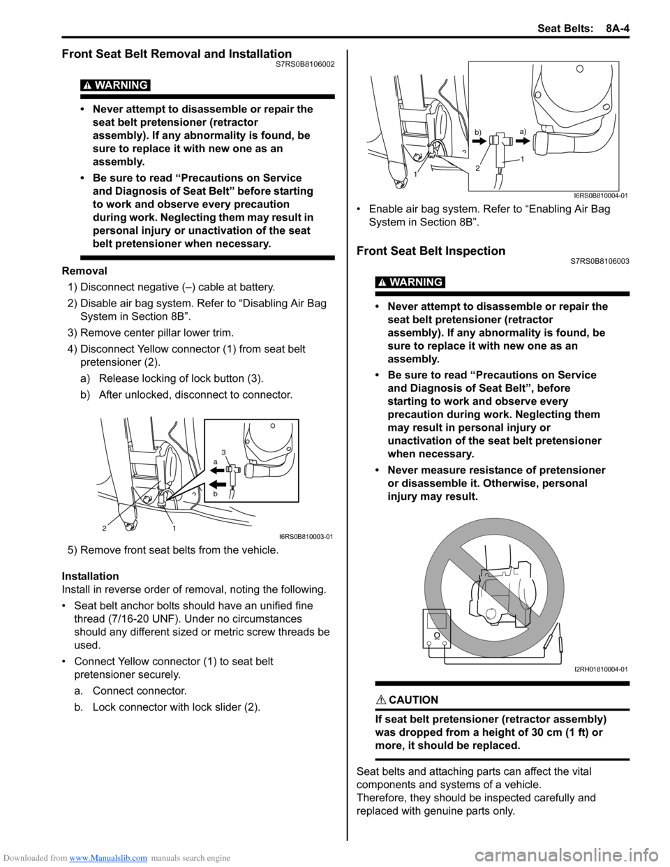
4) Disconnect Yellow connector (1) from seat belt pretensioner (2).
a) Release locking of lock button (3).
b) After unlocked, disconnect to connector.
5) Remove front seat belts from the vehicle.
Installation
Install in reverse order of removal, noting the following.
• Seat belt anchor bolts should have an unified fine thread (7/16-20 UNF). Under no circumstances
should any different sized or metric screw threads be
used.
• Connect Yellow connector (1) to seat belt pretensioner securely.
a. Connect connector.
b. Lock connector with lock slider (2). • Enable air bag system. Refer to “Enabling Air Bag
System in Section 8B”.
Front Seat Belt InspectionS7RS0B8106003
WARNING!
• Never attempt to disassemble or repair the seat belt pretensioner (retractor
assembly). If any abnormality is found, be
sure to replace it with new one as an
assembly.
• Be sure to read “Precautions on Service and Diagnosis of Seat Belt”, before
starting to work and observe every
precaution during work. Neglecting them
may result in personal injury or
unactivation of the seat belt pretensioner
when necessary.
• Never measure resistance of pretensioner or disassemble it. Otherwise, personal
injury may result.
CAUTION!
If seat belt pretensioner (retractor assembly)
was dropped from a height of 30 cm (1 ft) or
more, it should be replaced.
Seat belts and attaching parts can affect the vital
components and systems of a vehicle.
Therefore, they should be inspected carefully and
replaced with genuine parts only.
a
b
21 3I6RS0B810003-01
1
1
2
b)
a)
I6RS0B810004-01
I2RH01810004-01
Page 1065 of 1496
Downloaded from www.Manualslib.com manuals search engine Air Bag System: 8B-27
3 1) With ignition switch OFF, disconnect SDM connector “L29”.
2) Check proper connection to SDM at terminals “L29-3” and “L29-4”.
3) If OK, release shorting bar in SDM connector inserting
release tool (1) included in special tool (A).
4) Measure resistance between “L29-3” and “L29-4” terminals with connected special tools (B) and (D).
Special tool
(A): 09932-76010
(B): 09932-75010
(D): 09932–77320
Is resistance 3.85
Ω or less? Substitute a known-
good SDM and recheck.
High resistance or open
wire in “GRN/RED” or
“GRN” circuit in floor
harness.
Step Action Yes No
(A)
"L29-4"
"L29-3"
(B) (D)
"L32"BASE OF COLUMN
DRIVERPASSENGER
I7RS0A820011-03
Page 1070 of 1496
Downloaded from www.Manualslib.com manuals search engine 8B-32 Air Bag System:
3 1) With ignition switch OFF, disconnect SDM connector “L29”.
2) Check proper connection to SDM at terminals “L29-3” and “L29-4”.
3) If OK, release shorting bar in SDM connector inserting
release tool (1) included in special tool (A).
4) Measure resistance between “L29-3” and “L29-4” terminals with connected special tool (B) and (D).
Special tool
(A): 09932-76010
(B): 09932-75010
(D): 09932–77320
Is resistance 2.1
Ω or more? Substitute a known-
good SDM and recheck.
“GRN/RED” circuit
shorted to “GRN” circuit,
“GRN/RED” circuit or
“GRN” circuit shorted to
other circuit in floor
harness.
Step Action Yes No
(A)
"L29-4"
"L29-3"
(B) (D)
"L32"BASE OF COLUMN
DRIVERPASSENGER
I7RS0A820011-03
Page 1075 of 1496
Downloaded from www.Manualslib.com manuals search engine Air Bag System: 8B-37
3 1) With ignition switch OFF, disconnect special tools (B) and (D) from “L32” connector and SDM connector “L29”
from SDM respectively.
2) Release Shorting bar in SDM connector inserting release tool (1) included in special tool (A).
3) Measure resistance between “L29-3” terminal and body ground and between “L29-4” terminal and body ground.
Special tool
(A): 09932-76010
(B): 09932-75010
(D): 09932–78340
Are resistances infinity? Substitute a known-
good SDM and recheck.
“GRN/RED” circuit or
“GRN” circuit shorted to
ground in floor harness.
Step Action Yes No
(B) (D)
"L32"BASE OF COLUMN
DRIVERPASSENGER
(A)
"L29-4"
"L29-3"
I7RS0A820012-03
Page 1080 of 1496
Downloaded from www.Manualslib.com manuals search engine 8B-42 Air Bag System:
3 1) With ignition switch OFF, disconnect special tools (B) and (D) from “L32” connector and SDM connector “L29”
from SDM respectively.
2) Release Shorting bar in SDM connector inserting release tool (1) included in special tool (A).
3) Measure voltage from “L29-3” terminal to body ground and between “L29-4” terminal to body ground.
Special tool
(A): 09932-76010
(B): 09932-75010
(D): 09932–77320
With ignition switch ON, is each measured value 1 V or less? Substitute a known-
good SDM and recheck.
“GRN/RED” circuit or
“GRN” circuit shorted to
power supply circuit.
Step Action Yes No
(B) (D)
"L32"BASE OF COLUMN
DRIVERPASSENGER
(A)
"L29-4"
"L29-3"
I7RS0A820012-03