2008 SUZUKI SWIFT Direction
[x] Cancel search: DirectionPage 1007 of 1496
Downloaded from www.Manualslib.com manuals search engine Air Conditioning System: Automatic Type 7B-59
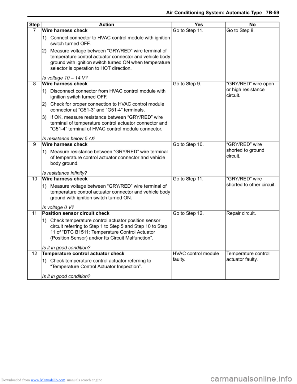
7Wire harness check
1) Connect connector to HVAC control module with ignition
switch turned OFF.
2) Measure voltage between “GRY/RED” wire terminal of temperature control actuator connector and vehicle body
ground with ignition switch turned ON when temperature
selector is operation to HOT direction.
Is voltage 10 – 14 V? Go to Step 11. Go to Step 8.
8 Wire harness check
1) Disconnect connector from HVAC control module with
ignition switch turned OFF.
2) Check for proper connection to HVAC control module connector at “G51-3” and “G51-4” terminals.
3) If OK, measure resistance between “GRY/RED” wire terminal of temperature control actuator connector and
“G51-4” terminal of HVAC control module connector.
Is resistance below 5
Ω? Go to Step 9. “GRY/RED” wire open
or high resistance
circuit.
9 Wire harness check
1) Measure resistance between “GRY/RED” wire terminal
of temperature control actuator connector and vehicle
body ground.
Is resistance infinity? Go to Step 10. “GRY/RED” wire
shorted to ground
circuit.
10 Wire harness check
1) Measure voltage between “GRY/RED” wire terminal of
temperature control actuator connector and vehicle body
ground with ignition switch turned ON.
Is voltage 0 V? Go to Step 11. “GRY/RED” wire
shorted to other circuit.
11 Position sensor circuit check
1) Check temperature control actuator position sensor
circuit referring to Step 1 to Step 5 and Step 10 to Step
11 of “DTC B1511: Temperature Control Actuator
(Position Sensor) and/or Its Circuit Malfunction”.
Is it in good condition? Go to Step 12. Repair circuit.
12 Temperature control actuator check
1) Check temperature control actuator referring to
“Temperature Control Actuator Inspection”.
Is it in good condition? HVAC control module
faulty.
Temperature control
actuator faulty.
Step Action Yes No
Page 1008 of 1496
Downloaded from www.Manualslib.com manuals search engine 7B-60 Air Conditioning System: Automatic Type
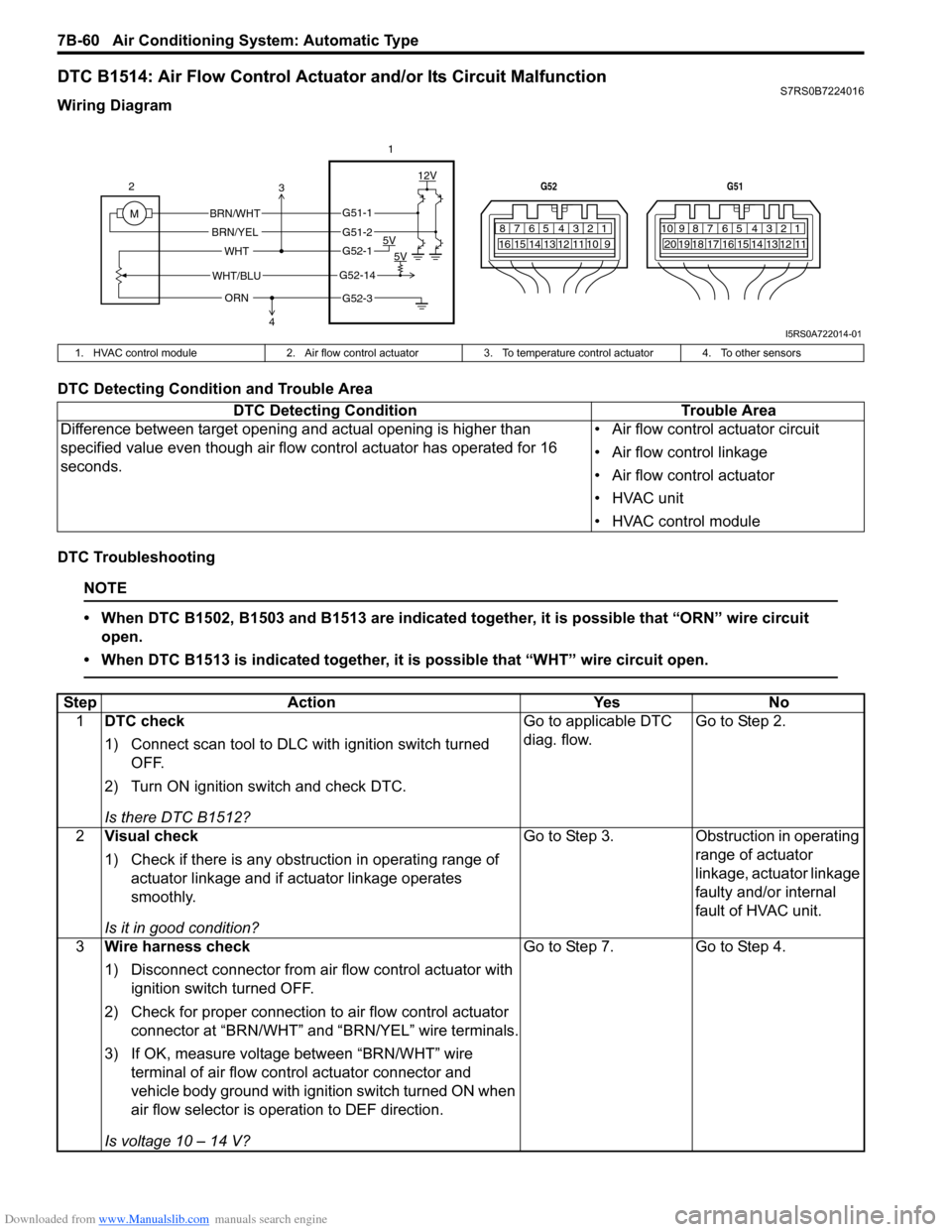
DTC B1514: Air Flow Control Actuator and/or Its Circuit MalfunctionS7RS0B7224016
Wiring Diagram
DTC Detecting Condition and Trouble Area
DTC Troubleshooting
NOTE
• When DTC B1502, B1503 and B1513 are indicated together, it is possible that “ORN” wire circuit open.
• When DTC B1513 is indicated together, it is possible that “WHT” wire circuit open.
7812910
65 431516 14 13 12 11
G52
789101920121112
65 431718 16 15 14 13
G51
M 12V
5V 5V
WHT/BLU
WHT
BRN/WHT
BRN/YEL
2
1
ORN
G51-1
G51-2
G52-1
G52-14
G52-3
3
4
I5RS0A722014-01
1. HVAC control module 2. Air flow control actuator3. To temperature control actuator 4. To other sensors
DTC Detecting Condition Trouble Area
Difference between target opening and actual opening is higher than
specified value even though air flow control actuator has operated for 16
seconds. • Air flow control actuator circuit
• Air flow control linkage
• Air flow control actuator
• HVAC unit
• HVAC control module
Step
Action YesNo
1 DTC check
1) Connect scan tool to DLC with ignition switch turned
OFF.
2) Turn ON ignition switch and check DTC.
Is there DTC B1512? Go to applicable DTC
diag. flow.
Go to Step 2.
2 Visual check
1) Check if there is any obstruction in operating range of
actuator linkage and if actuator linkage operates
smoothly.
Is it in good condition? Go to Step 3.
Obstruction in operating
range of actuator
linkage, actuator linkage
faulty and/or internal
fault of HVAC unit.
3 Wire harness check
1) Disconnect connector from air flow control actuator with
ignition switch turned OFF.
2) Check for proper connection to air flow control actuator
connector at “BRN/WHT” and “BRN/YEL” wire terminals.
3) If OK, measure voltage between “BRN/WHT” wire terminal of air flow control actuator connector and
vehicle body ground with ignition switch turned ON when
air flow selector is operation to DEF direction.
Is voltage 10 – 14 V? Go to Step 7.
Go to Step 4.
Page 1009 of 1496
Downloaded from www.Manualslib.com manuals search engine Air Conditioning System: Automatic Type 7B-61
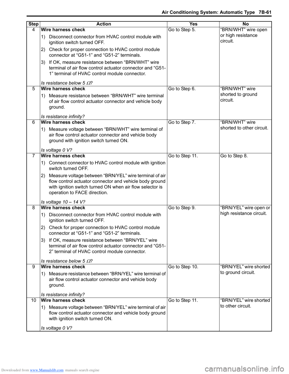
4Wire harness check
1) Disconnect connector from HVAC control module with
ignition switch turned OFF.
2) Check for proper connection to HVAC control module connector at “G51-1” and “G51-2” terminals.
3) If OK, measure resistance between “BRN/WHT” wire terminal of air flow contro l actuator connector and “G51-
1” terminal of HVAC control module connector.
Is resistance below 5
Ω? Go to Step 5. “BRN/WHT” wire open
or high resistance
circuit.
5 Wire harness check
1) Measure resistance between “BRN/WHT” wire terminal
of air flow control actuator connector and vehicle body
ground.
Is resistance infinity? Go to Step 6.
“BRN/WHT” wire
shorted to ground
circuit.
6 Wire harness check
1) Measure voltage between “BRN/WHT” wire terminal of
air flow control actuator connector and vehicle body
ground with ignition switch turned ON.
Is voltage 0 V? Go to Step 7.
“BRN/WHT” wire
shorted to other circuit.
7 Wire harness check
1) Connect connector to HVAC control module with ignition
switch turned OFF.
2) Measure voltage between “BRN/YEL” wire terminal of air flow control actuator connector and vehicle body ground
with ignition switch turned ON when air flow selector is
operation to FACE direction.
Is voltage 10 – 14 V? Go to Step 11. Go to Step 8.
8 Wire harness check
1) Disconnect connector from HVAC control module with
ignition switch turned OFF.
2) Check for proper connection to HVAC control module connector at “G51-1” and “G51-2” terminals.
3) If OK, measure resistance between “BRN/YEL” wire terminal of air flow contro l actuator connector and “G51-
2” terminal of HVAC control module connector.
Is resistance below 5
Ω? Go to Step 9. “BRN/YEL” wire open or
high resistance circuit.
9 Wire harness check
1) Measure resistance between “BRN/YEL” wire terminal of
air flow control actuator connector and vehicle body
ground.
Is resistance infinity? Go to Step 10. “BRN/YEL” wire shorted
to ground circuit.
10 Wire harness check
1) Measure voltage between “BRN/YEL” wire terminal of air
flow control actuator connector and vehicle body ground
with ignition switch turned ON.
Is voltage 0 V? Go to Step 11. “BRN/YEL” wire shorted
to other circuit.
Step Action Yes No
Page 1036 of 1496
Downloaded from www.Manualslib.com manuals search engine 8A-5 Seat Belts:
Seat Belt
• The seat belt webbing or strap should be free from damage.
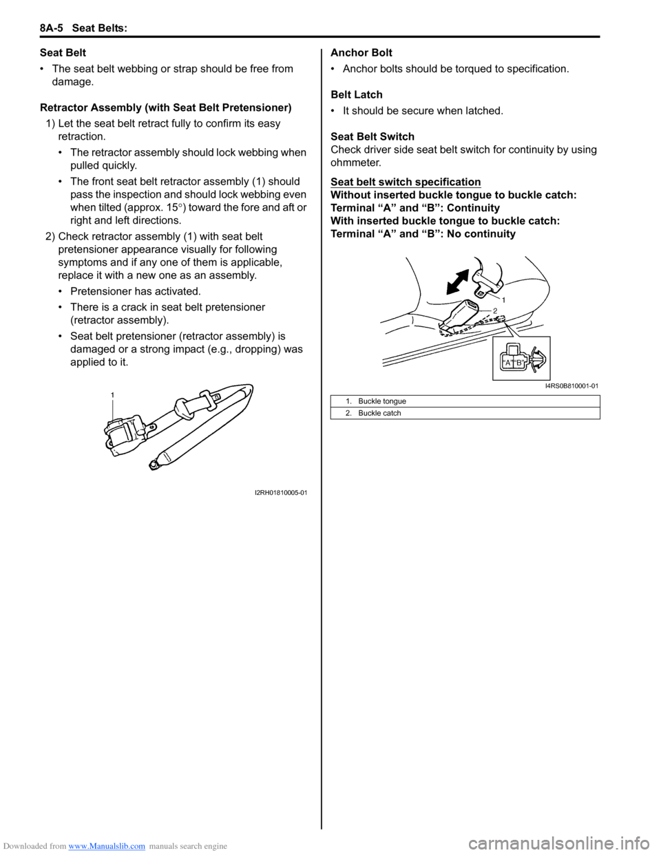
Retractor Assembly (with Seat Belt Pretensioner) 1) Let the seat belt retract fully to confirm its easy retraction.
• The retractor assembly should lock webbing when
pulled quickly.
• The front seat belt retractor assembly (1) should pass the inspection and should lock webbing even
when tilted (approx. 15 °) toward the fore and aft or
right and left directions.
2) Check retractor assembly (1) with seat belt pretensioner appearance visually for following
symptoms and if any one of them is applicable,
replace it with a new one as an assembly.
• Pretensioner has activated.
• There is a crack in seat belt pretensioner (retractor assembly).
• Seat belt pretensioner (retractor assembly) is damaged or a strong impact (e.g., dropping) was
applied to it. Anchor Bolt
• Anchor bolts should be torqued to specification.
Belt Latch
• It should be secure when latched.
Seat Belt Switch
Check driver side seat belt s
witch for continuity by using
ohmmeter.
Seat belt switch specification
Without inserted buckle tongue to buckle catch:
Terminal “A” and “B”: Continuity
With inserted buckle tongue to buckle catch:
Terminal “A” and “B”: No continuity
I2RH01810005-01
1. Buckle tongue
2. Buckle catch
I4RS0B810001-01
Page 1154 of 1496
Downloaded from www.Manualslib.com manuals search engine 8B-116 Air Bag System:
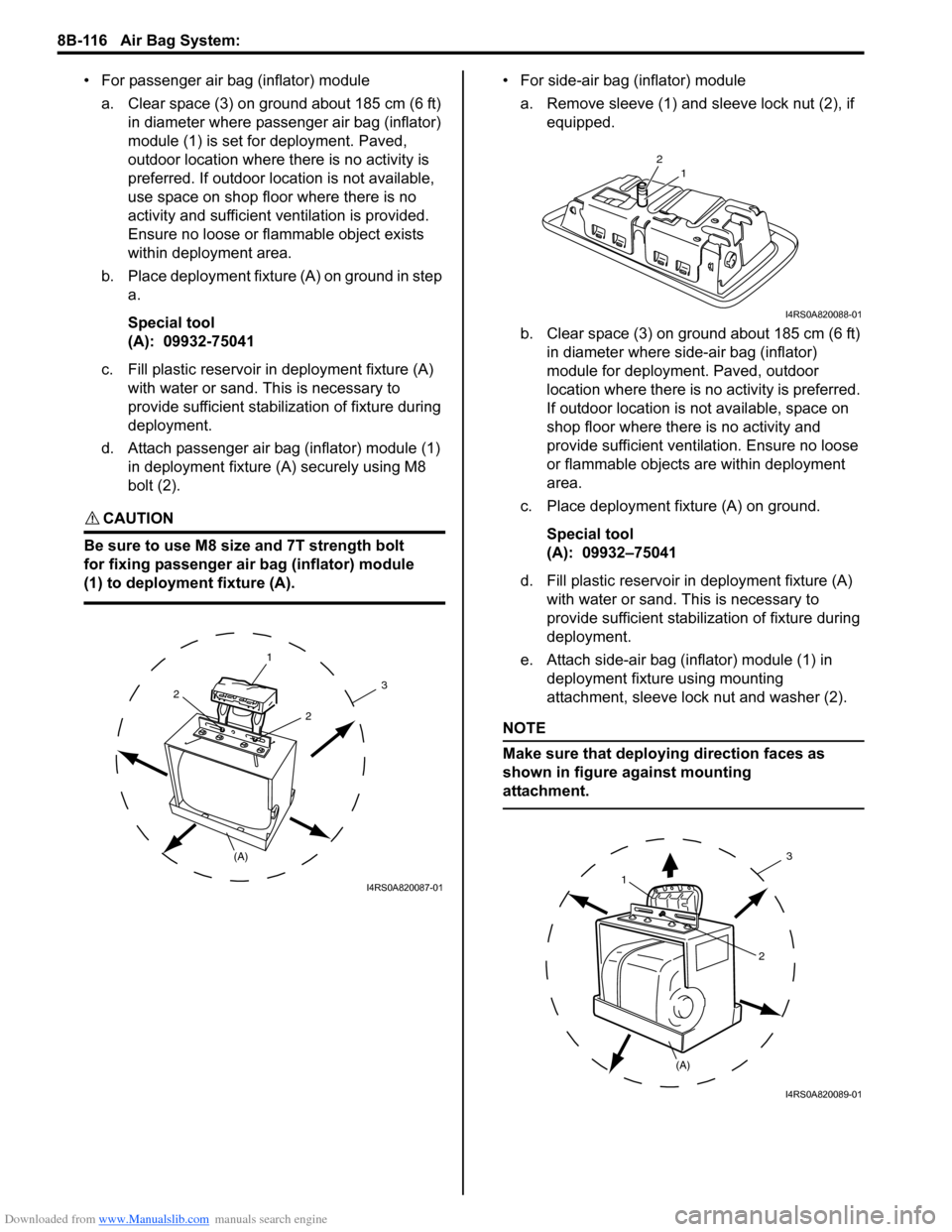
• For passenger air bag (inflator) modulea. Clear space (3) on ground about 185 cm (6 ft) in diameter where passenger air bag (inflator)
module (1) is set for deployment. Paved,
outdoor location where there is no activity is
preferred. If outdoor location is not available,
use space on shop floor where there is no
activity and sufficient ventilation is provided.
Ensure no loose or flammable object exists
within deployment area.
b. Place deployment fixture (A) on ground in step a.
Special tool
(A): 09932-75041
c. Fill plastic reservoir in deployment fixture (A) with water or sand. Th is is necessary to
provide sufficient stabilization of fixture during
deployment.
d. Attach passenger air bag (inflator) module (1) in deployment fixture (A ) securely using M8
bolt (2).
CAUTION!
Be sure to use M8 size and 7T strength bolt
for fixing passenger air bag (inflator) module
(1) to deployment fixture (A).
• For side-air bag (inflator) module
a. Remove sleeve (1) and sl eeve lock nut (2), if
equipped.
b. Clear space (3) on ground about 185 cm (6 ft) in diameter where side-air bag (inflator)
module for deployment. Paved, outdoor
location where there is no activity is preferred.
If outdoor location is not available, space on
shop floor where there is no activity and
provide sufficient ventilation. Ensure no loose
or flammable objects are within deployment
area.
c. Place deployment fixture (A) on ground.
Special tool
(A): 09932–75041
d. Fill plastic reservoir in deployment fixture (A) with water or sand. Th is is necessary to
provide sufficient stabiliz ation of fixture during
deployment.
e. Attach side-air bag (inflator) module (1) in deployment fixture using mounting
attachment, sleeve lock nut and washer (2).
NOTE
Make sure that deploying direction faces as
shown in figure against mounting
attachment.
1
(A)
2
2
3
I4RS0A820087-01
21
I4RS0A820088-01
1
(A) 2
3
I4RS0A820089-01
Page 1179 of 1496
Downloaded from www.Manualslib.com manuals search engine Wiring Systems: 9A-8
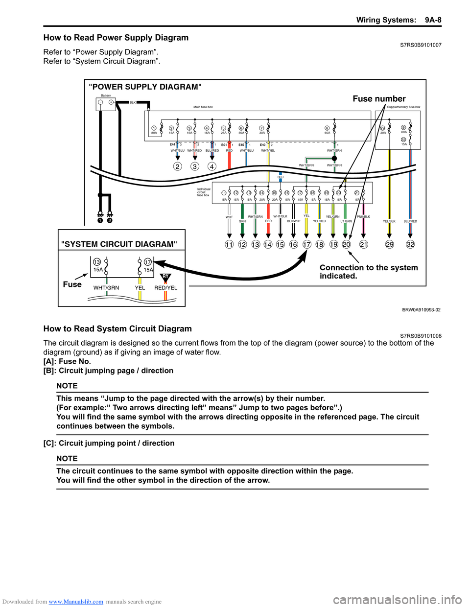
How to Read Power Supply DiagramS7RS0B9101007
Refer to “Power Supply Diagram”.
Refer to “System Circuit Diagram”.
How to Read System Circuit DiagramS7RS0B9101008
The circuit diagram is designed so the current flows from the top of the diagram (power source) to the bottom of the
diagram (ground) as if giving an image of water flow.
[A]: Fuse No.
[B]: Circuit jumping page / direction
NOTE
This means “Jump to the page directed with the arrow(s) by their number.
(For example:” Two arrows directing left” means” Jump to two pages before”.)
You will find the same symbol with the arrows directing opposite in the referenced page. The circuit
continues between the symbols.
[C]: Circuit jumping point / direction
NOTE
The circuit continues to the same symbol with opposite direction within the page.
You will find the other symbol in the direction of the arrow.
Connection to the system
indicated.
"POWER SUPPLY DIAGRAM"
-+
1
Battery
80A
215A315A415A525A67850A 30A2930A3215A
960A
60A
BLK
YEL/BLKPNK/BLKLT GRNYEL/GRNYEL/BLUBLK/WHTWHT/BLKWHT/GRNREDGRNWHT
WHT/BLUWHT/REDWHT/BLUWHT/YELWHT/GRN
WHT/GRNWHT/GRN
BLU
BLU/REDRED
YELBLU/RED
Individual
circuit
fuse box
Main fuse box
Supplementary fuse box
11
11
243
121314151617181920212932
1213141516171819202115A 15A 15A 20A 20A 15A 15A 15A 15A 15A 15A
E44
321
B011E45 1 E4021
FuseRED/YEL
YEL
WHT/GRN
15A
15A
1317
"SYSTEM CIRCUIT DIAGRAM"
Fuse number
1
2
RY
I5RW0A910993-02
Page 1292 of 1496
Downloaded from www.Manualslib.com manuals search engine 9B-10 Lighting Systems:
Turn Signal and Hazard Warning Relay
Inspection
S7RS0B9206012
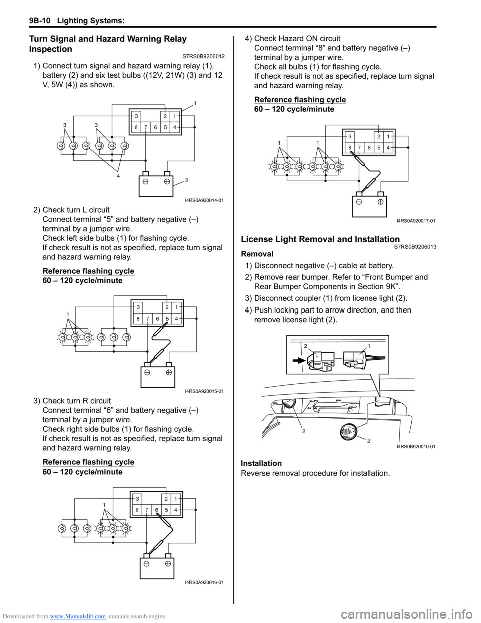
1) Connect turn signal and hazard warning relay (1), battery (2) and six test bulbs ((12V, 21W) (3) and 12
V, 5W (4)) as shown.
2) Check turn L circuit Connect terminal “5” and battery negative (–)
terminal by a jumper wire.
Check left side bulbs (1) for flashing cycle.
If check result is not as specified, replace turn signal
and hazard warning relay.
Reference flashing cycle
60 – 120 cycle/minute
3) Check turn R circuit Connect terminal “6” and battery negative (–)
terminal by a jumper wire.
Check right side bulbs (1) for flashing cycle.
If check result is not as specified, replace turn signal
and hazard warning relay.
Reference flashing cycle
60 – 120 cycle/minute 4) Check Hazard ON circuit
Connect terminal “8” and battery negative (–)
terminal by a jumper wire.
Check all bulbs (1) for flashing cycle.
If check result is not as sp ecified, replace turn signal
and hazard warning relay.
Reference flashing cycle
60 – 120 cycle/minute
License Light Removal and InstallationS7RS0B9206013
Removal
1) Disconnect negative (–) cable at battery.
2) Remove rear bumper. Refe r to “Front Bumper and
Rear Bumper Components in Section 9K”.
3) Disconnect coupler (1) from license light (2).
4) Push locking part to arrow direction, and then remove license light (2).
Installation
Reverse removal procedure for installation.
2
4
33
3
87
12
654
1
I4RS0A920014-01
13
87
12
654
I4RS0A920015-01
3
87
12
6541
I4RS0A920016-01
3
87
12
6
5411
I4RS0A920017-01
2
2
1
2
I4RS0B920010-01
Page 1310 of 1496
Downloaded from www.Manualslib.com manuals search engine 9C-15 Instrumentation / Driver Info. / Horn:
Combination Meter Removal and InstallationS7RS0B9306003
Removal1) Disconnect negative (–) cable at battery.
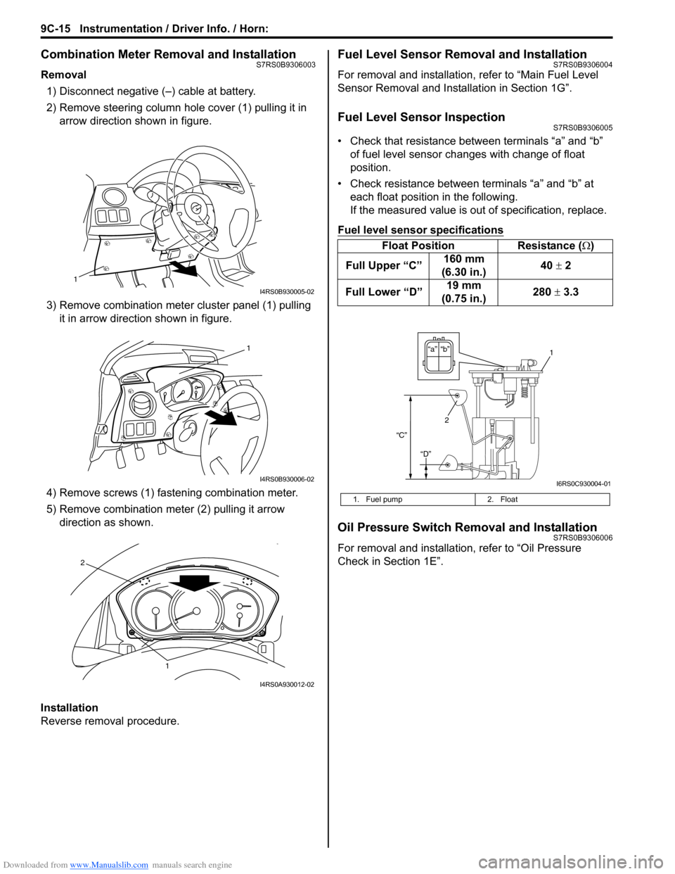
2) Remove steering column hole cover (1) pulling it in arrow direction shown in figure.
3) Remove combination mete r cluster panel (1) pulling
it in arrow direction shown in figure.
4) Remove screws (1) fast ening combination meter.
5) Remove combination me ter (2) pulling it arrow
direction as shown.
Installation
Reverse removal procedure.
Fuel Level Sensor Removal and InstallationS7RS0B9306004
For removal and installation, refer to “Main Fuel Level
Sensor Removal and Installation in Section 1G”.
Fuel Level Sensor InspectionS7RS0B9306005
• Check that resistance between terminals “a” and “b” of fuel level sensor changes with change of float
position.
• Check resistance between terminals “a” and “b” at each float position in the following.
If the measured value is out of specification, replace.
Fuel level sensor specifications
Oil Pressure Switch Removal and InstallationS7RS0B9306006
For removal and installation , refer to “Oil Pressure
Check in Section 1E”.
1
I4RS0B930005-02
1
I4RS0B930006-02
1
2
I4RS0A930012-02
Float Position Resistance (Ω)
Full Upper “C” 160 mm
(6.30 in.) 40
± 2
Full Lower “D” 19 mm
(0.75 in.) 280
± 3.3
1. Fuel pump 2. Float
“b”“a”
2
“C”
“D”
1
I6RS0C930004-01